

J. Cent. South Univ. (2018) 25: 586-599
DOI: https://doi.org/10.1007/s11771-018-3763-2

H�� control of an overactuated tilt rotors quadcopter
Ahmed ALKAMACHI1, Ergun ER ELEB
ELEB 2
2
1. Department of Mechatronics, Al Khwarizmi College of Engineering, University of Baghdad,Baghdad 10071, Iraq;
2. Department of Electric and Electronic Engineering, Gaziantep University, Gaziantep 27310, Turkey
 Central South University Press and Springer-Verlag GmbH Germany, part of Springer Nature 2018
Abstract:
In recent years, unmanned aerial vehicles (UAVs) have acquired an increasing interest due to their wide range of applications in military, scientific, and civilian fields. One of the quadcopter limitations is its lack of full actuation property which limits its mobility and trajectory tracking capabilities. In this work, an overactuated quadcopter design and control, which allows independent tilting of the rotors around their arm axis, is presented. Quadcopter with this added tilting mechanism makes it possible to overcome the aforementioned mobility limitation by achieving full authority on torque and force vectoring. The tilting property increases the control inputs to 8 (the 4 propeller rotation speed plus the 4 rotor tilting angles) which gives a full control on the quadcopter states. Extensive mathematical model for the tilt rotor quadcopter is derived based on the Newton-Euler method. Furthermore, the feedback linearization method is used to linearize the model and a mixed sensitivity H�� optimal controller is then designed and synthesized to achieve the required performance and stability. The controlled system is simulated to assure the validity of the proposed controller and the quadcopter design. The controller is tested for its effectiveness in rejecting disturbances, attenuating sensor noise, and coping with the model uncertainties. Moreover, a complicated trajectory is examined in which the tilt rotor quadcopter has been successfully followed. The test results show the supremacy of the overactuated quadcopter over the traditional one.
Key words:
feedback linearization; H�� controller; Newton-Euler method; overactuated quadcopter; robust control��
Cite this article as:
Ahmed ALKAMACHI, Ergun ERELEB. H�� control of an overactuated tilt rotors quadcopter [J]. Journal of Central South University, 2018, 25(3): 586�C599.
1 Introduction
Unmanned aerial vehicles (UAVs) can be classified according to their lift method into two main types: fixed�Cwing aircrafts, and rotorcrafts. Quadcopter classified as a rotorcraft is one of the most popular designs of UAV. Its vertical take off landing (VTOL) ability, simplicity in design, high maneuverability, low cost, and the ability of moving into a cramped area make it possible to be used in several applications in different military and civilian fields. The state of the art in the quadrotor design and control shows a significant change in the last decade. Quadcopter with full 6 degree of freedoms (DoFs) control will be a base for many applications that require a precise control on the quadcopter states like the flying service robots.
Traditional quadcopter is considered an underactuated system since it has only 4 control inputs (the 4 propellers�� spinning speed) against 6 DoFs. Its underactuation property results in a lack of controlling its position/orientation independently and consequently prevents it from following arbitrary trajectories. For example, the quadcopter should tilt its body to move along the desired direction, in other words, it should be horizontal to hover at a point in the space. Substantial academic resources have been reviewed in thrust vectoring methods, new design configurations, modelling,stabilization, and control of quadrotors. Many breakthroughs have been emerged and several concepts have been proposed by researchers trying to overcome the underactuation problem and to improve the standard quadrotors.
One of the well-known configurations is the quad tilt rotor (QTR). Instead of tilting the UAV, its rotor can also be tilted all together. QTR can change its mode of flight from helicopter mode to aircraft mode and vice versa by tilting all its four rotors at once [1]. Another research in this field was done by ETINSOY et al [2] who proposed a quad tilt wing UAV which can switch between helicopter and aircraft mode by tilting the four rotors all at the same time. Omni Flymobile is a quadrotor model proposed by JEONG et al [3]. The design allows the switching between quadrotor and aircraft mode by changing the tilt angle of the rotors from 0o to 90o. Following similar concept, KENDOUL et al [4] discussed tilting of two rotors in small autonomous aircraft. As another solution for the underactuation problem, ONER et al [5] suggested tilt wing mechanisms. The aim of Ref. [6] is to present a mini tilt rotor UAV in which two tiltable propellers are responsible of UAV stabilization during hovering. MOHAMED et al [7] proposed a tri-rotor model that can achieve 6 DoFs by adding an independent tilting mechanism to its three rotors. RYLL et al [8] presented a PID controlled tiltable rotors UAV in which each propeller had the ability to tilt along the axis connecting it to the main body. In a similar technique, a novel actuation method has been proposed to overcome the basic limitation of the quadrotor by adding one dimensional tilt property to each of the four propellers of the quadrotor [9-10]. Looking for more improvement of the quadrotor actuation,  ENKUL et al [11] and ELFEKY et al [12] proposed two axis tilting properties to each of the four rotors of the quadrotor. Their design has been modeled and verified using MATLAB simulation and it shows a better performance over the fixed propellers quadrotors.
The main contributions in our work can be summarized by:
1) The unique step-by-step mathematical modeling procedure for a tilt rotor quadcopter.
2) The conceptualization of the tilting-based overactuation mechanism for a quadrotor.
3) The application of input-output feedback linearization to the complex nonlinear quadcopter model to design a linear controller.
4) The design and synthesis of a mixed sensitivity optimal H�� controller for an overactuated tilt rotor quadcopter for following complex trajectories.
The quadcopter design in this work offers an independent and free control over the quadcopter states. To ensure the system robustness against the unmodelled dynamics and the model uncertainties, optimal H�� controller is designed and synthesized to control our model.
The rest of the paper sections are organized as follows: Section 2 describes the static and dynamic mathematical model of the overactuated tilt rotor quadrotor. The control scheme is presented in Section 3. Section 4 presents the model simulation and the simulation results for several tests. The paper concludes in Section 5.
2 System model
The dynamic model of a system is the mathematical set of equations that combine all the forces that can act on a system at a given time [13]. The quadrotor is a multi-input multi-output (MIMO) system. It has a complex structure with nonlinear dynamics, and hence writing its mathematical model equations is not an easy task [14, 15].
In order to describe the quadcopter states, which are the three position coordinates (x, y, z) and the three orientation angles (f, ��, ��), the mathematical model should investigate both the translational and angular dynamics [16]. The aim of this section is to define a relationship between the 6 DoFs of the system with the spinning speeds and the tilt angles of the four rotors.
In general, two main modelling methods are used to exhibit the quadrotor models. These methods are the Lagrange-Euler and Newton-Euler method. Despite the useful compact form of the Lagrang-Euler method, Newton-Euler is widely used due to its simplicity in describing the model physically [17], therefore it is used in describing the quadcopter system dynamics through this work.
2.1 System configuration and design
The tilt-rotor quadcopter will be denoted as QTRcopter throughout the remaining of this work. The configuration, Cartesian axes, and the rotor numbers are shown in Figure 1(a). The QTRcopter structure consists of 5 main bodies which are four rotor groups (�٨C��)connected to a central body through four identical arms. At the end of each arm there is a guided force generating unit which consists of a brushless DC (BLDC) rotor with fixed pitch propeller. The rotor-propeller set is attached to the quadcopter arm through a servo motor which is responsible of vectoring the generated force into horizontal and vertical component. The rotor tilt configuration is shown in Figure 1(b). The tilt angle of the rotor�Cpropeller set will range from �C��/2 to ��/2 rad around the arm extension axis. The four forces generating units can be tilted independently so the quadcopter has a full control on force vectoring.
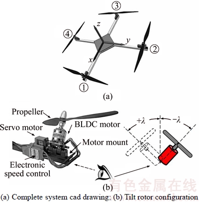
Figure 1 QTRcopter configuration:
2.2 Coordinate systems
Two basic frames and two sub frames are used during the model derivation. The basic frames are the earth frame and body frame, while for each rotor group, there are two sub frames centered at each servo motor.
These sub frames are denoted as auxiliary frames. Figure 2 shows the main and auxiliary frames of QTRcopter.
The variables belong to the earth frame left superscripted with letter ��E��, and that referred to the body frame are with ��B�� left superscript. Since the rotor group assumed to be another body, then a new frame related to each rotor is defined and the variables belong to the ith rotor frame will have ��Pi�� left superscript and these belong to the ith servo frame will take ��Si��, where i=(1, 2, 3, 4). The right hand side system is used for all the frames as shown in Figure 2. Auxiliary frame origin coincides with the point of coupling between the rotors and UAV arms where the rotor group will be capable of tilting around its x-coordinates.
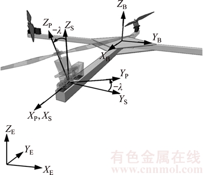
Figure 2 Main and auxiliary reference frames of QTRcopter
The rotation matrices, that are used to transfer variable vectors between the previously defined frames, are based on the following basic rotation matrices which rotate vectors by an angle ��x, ��y, and ��z about x, y, and z axis respectively:
 (1)
(1)
 (2)
(2)
 (3)
(3)
where S(��) and C(��) represent the sine and cosine functions respectively.
A vector which originally located at FPi can be expressed in FSi by post multiplying it by a rotation matrix SiRPi which represents a rotation about the arm axis with angle ��i and defined as:
 (4)
(4)
where i is the rotor number (i=1, 2, 3, 4).
In similar fashion, a vector can be rotated from FSi to FB using the following rotation matrix:
 (5)
(5)
where ��i=0, ��/2, �� and 3��/2 for i=1, 2, 3 and 4 respectively.
Like manner, a vector can be transformed from FE to FB by means of the following rotation matrix:

 (6)
(6)
where f, ��, and �� are the NASA based Euler angles that represent the roll, pitch and heading (yaw) angles, respectively [18].
2.3 Important assumptions for simplification
The quadrotor system structure is physically complicated and its mathematical modelling without some simplifying assumptions will result in complicated equations [19, 20].For example, due to the slow velocities while hovering, the aerodynamic effects of the system can be neglected [17]. The gyroscopic effect can also be neglected since most of the quadcopter mass concentrates in its core [21].
The following important assumptions also can be applied in order to simplify the model [22, 23]:
1) The quadrotor structure is supposed to be symmetric.
2) The overall system structure is assumed to be rigid.
3) The centre of gravity (COG) of the quadrotor and its body frame origin is coinciding.
2.4 Mathematical model
In this section, the dynamics of our model are described mathematically. All the forces and torques that are acting on the quadcopter body should be obtained to write the system model. Based on blade element theory (BET) and momentum theory, it can be seen that the rotor thrust and torque are proportional to the square of the rotor speed [24, 25] as it will be used later in this section.
2.4.1 Force
The forces acting on the UAV can be divided into the propulsive force and the gravitational force. Each rotor generates a propulsive force when rotating, therefore, the overall propulsive force is the algebraic sum of that generated by the four rotors. The propulsive force for each rotor can be expressed separately in its ith rotor coordinates as [26]:
 (7)
(7)
These individual forces should be expressed in FB by post multiplying it with SiRPi and then by BRSi as follows:
 (8)
(8)
Then, the total propulsive force acting on the QTRcopter body is the sum of the individual forces generated by the four spinning propellers, that is:
 (9)
(9)
where

and


The other force which acts on the quadcopter is the gravitational force which can be expressed in FB as:
 (10)
(10)
and the total force acting on the quadcopter is the sum of that due to the propellers spinning BFTR and the gravitational force BFg expressed in the body frame.
 (11)
(11)
2.4.2 Torque
Propeller spinning results in two types of torques: reactive torque and drag torque. The reactive or propulsive torque is a torque resulting from the propulsive force around the center of gravity of the UAV. In our system, we have four rotors attached to four identical arms and the reactive torque for each individual rotor can be expressed in the body coordinate as:
 (12)
(12)
where
 (13)
(13)
Drag torque is in the opposite of the direction of rotation of the propeller and it is a result of aerodynamic drag force. The ith propeller approximated drag torque, expressed in FB is equal to [27]:
 (14)
(14)
where Ti is negative for propellers rotating clockwise (CW) (propellers 1 and 2) and positive for counter clockwise (CCW) propellers (propellers 3 and 4).
The total torque acting on the COG of the UAV expressed in FB is:
 (15)
(15)
where

The complete static model can be obtained by expressing the total force and torque acting on the system and combining them into one matrix equation as follows:
 (16)
(16)
where 03��1 is a 3��1 zero matrix.
Concerning the dynamic model, according to the Newton-Euler method, the force and torque with respect to the quadcopter body frame are expressed in the following matrix form:
 (17)
(17)
where I3��3 and 03��3 are a 3��3 identity and zero matrix, respectively.
Form the above matrix equation, we can find that  and
and  are:
are:
 (18)
(18)
 (19)
(19)
then, the following two equations are used to describe the system dynamics:
 (20)
(20)
 (21)
(21)
3 Controller design
In this section, we start with Eqs. (18)�C(21) which govern the QTRcopter operation and behavior to design a suitable controller for our overactuated quadcopter.
In this work, a trajectory tracking control will be considered to control the position and the orientation of the quadcopter.
By examining the equations mentioned at the beginning of this section, one can see that the system is nonlinear. As a common approach to the tracking control problem, input�Coutput feedback linearization method is being used to transform the nonlinear system into an equivalent linear one that can be controlled using linear control techniques.
As seen in the previous sections, several assumptions have been made during the model derivation. For example, actuator dynamics and gyroscopic effect have been neglected; external disturbances (e.g., a light guest wind) are neglected too. For those reasons and to ensure the robustness of the stability and the performance, optimal H�� trajectory tracking controller is designed and synthesized to cope with the sensor noise, the external disturbances, and the model parameters uncertainties.
3.1 Feedback linearization
The feedback linearization approach produces a linear system whose states are the output and first (n�C1) derivatives can be found using Lie derivatives.
The inputs (u) to the system are the rotors�� speed and their tilt angles, while the outputs are the position of the quadrotor P and its orientation A (pitch, roll, and yaw angles).
The outputs, which are expressed in Eqs. (20) and (21), are differentiated again to get an equation relating them to the system inputs as:
 (22)
(22)
 (23)
(23)
According to Ref. [28], the time derivative of a rotation matrix is the same matrix multiplied by a skew symmetric matrix of the angular velocity, then
 (24)
(24)
where

Substituting Eqs. (18), (19) and (24) into Eqs. (22) and (23) yields:
 (25)
(25)
 (26)
(26)
Equations (25) and (26) can be combined into one compact matrix equation and after some arrangement and simplification by inserting Eq. (9) to Eq. (15) we get:

 (27)
(27)
In view of the linearization of system dynamics, we define a new virtual input v instead of u and let:
 (28)
(28)
The relationship between u and v is found to be:
 (29)
(29)
where

and

Now, the relative degree of the system should be calculated to check for zero dynamic and the controllability of the model [29]. Since the output variables (the position and the orientation) have been derived twice and it is a two state vector, then the relative degree of the system is 2+2=4 and is equal to the number of state vectors so there is no zero dynamics in the model under consideration.
The state space representation of the linearized model is:
 (30)
(30)

where


 is a state vector and
  is the outputs vector.
We have obtained the linearized system model which in fact represents a double integrator and can be controlled using any linear system control method.
3.2 H�� optimal controller design
We begin this section by defining the important terms and acronyms that generally used in the control system. The general control system block diagram is shown in Figure 3. This system could be single input single output (SISO) system or a multi-input multi-output (MIMO) system. G(s) represents the plant model which is the feedback linearization block in cascade with quadcopter model in our system. Although the tilt rotor quadcopter is a MIMO system, we can design an individual SISO controller for each quadcopter state thanks to the uncoupling between these states as illustrated in Eq.(30).
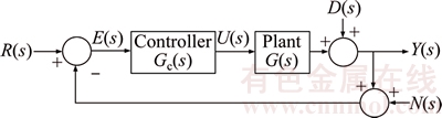
Figure 3 General feedback control system
The feedback control system in Figure 3 has three inputs (desired command input R(s), external disturbance D(s), and sensor measurement noise N(s)) and one output y(s). The controller Gc(s) uses the error signal E(s), which is the difference between the desired and actual output, to generate a suitable actuator signal u(s).
The output signal y(s) can be expressed in terms of the three inputs R(s), D(s) and N(s) as:

 (31)
(31)
where L(s)=G(s)*Gc(s) is the loop transfer function, T(s) is the closed loop transfer function, and S(s) is the sensitivity transfer function of the system. From the above, we can write:
 (32)
(32)
thus, T(s) is also known as complementary sensitivity function.
In the same way, E(s) and u(s) can be related to the system inputs by:
 (33)
(33)

 (34)
(34)
where K(s) is called the control signal sensitivity function.
From the above equations, we can find that for good tracking capability, it is required that y(s)=R(s) which can be attended if T(s)=1 and consequently S(s)=0. This can be achieved if the loop transfer function L(s) is made large. The same concept is also valid for good disturbance rejection. On the contrary, for good noise suppression, T(s) should be small which can be achieved if L(s) is small. Fortunately, the disturbance in general occurs at low frequencies and L(s) needs to be large in this band, while the measurement noise concentrates at high frequencies where L(s) needs to be small in these frequencies. To summarize, S(s) should be small at low frequencies for good disturbance rejection, and T(s) should be large at high frequencies for sensor noise attenuation.
In our design, we will make use of H�� concepts to design an optimal controller to meet the above shape requirements for S(s) and T(s).
The H�� norm of a rational function F(j��) is the largest distance between the origin and the Nyquist contour [30]. It is also equal to the maximum singular value over the entire spectrum.
 (35)
(35)
In Ref. [31], ZAMES considered the problem of designing a controller that can achieve the overall system stability and minimize the norm of the sensitivity function  The feedback control system is aimed to track signals up to a specific frequency since it is impossible to do so well in the entire spectrum especially at high frequencies. In this case, direct application of H�� optimal control might result in a poor response since it is designed with a uniform bound overall the spectrum, while some frequencies may be more interesting than others [32]. For this reason, a mixed sensitivity problem with three frequency- dependant weighting functions (We(s), Wu(s) and Wy(s)) are used to shape the S(s), R(s) and T(s) functions respectively in the frequencies of interests. The block diagram of a feedback control system with the three weighting functions is shown in Figure 4(a). The mixed sensitivity problem is a special case of H�� control methodology. The performance of the robust controller for a plant is basically dependent upon the selection of the weighting functions. Now, let us consider the block diagram for a standard control problem in Figure 4(b), where W(s) represents the inputs (desired input signal, disturbance, sensor noise, ��, etc.), u(s) is the actuator input, Z(s) is the output to be minimized (steady state error, ��, etc.), y(s) is the output to be controlled, P(s) is the generalized plant or so called augmented plant and it includes the plant G(s) and the three weighting functions, and Gc(s) is the feedback controller.
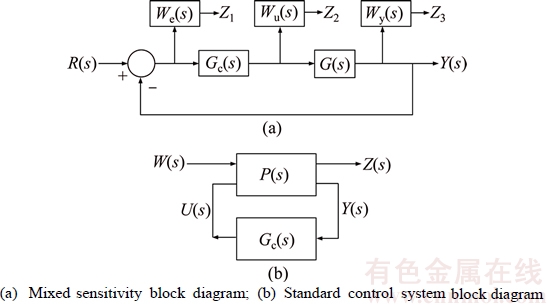
Figure 4 Control system block diagram:
The state space model for the augmented plant can be described as:

 (36)
(36)
and the transfer function from the input W to the output Z is:

 (37)
(37)
In the design of the mixed sensitivity optimal H�� controller, the weighting functions are used to determine a stabilizing controller for the feedback control system and minimize the cost function in Eq.(37), i.e.:
 (38)
(38)
As a first step in determining the controller Gc(s), it is required to design the three weighting functions efficiently and precisely. A suitable design and tune of the weighting functions is of great importance and it is not an easy task. One has to embed control system design experience, conjecture, and domain acquaintance in the robust controller design.
In this work, the design of the weighting functions is made based on trial and error process which has been used in many articles [33�C35].
Consider our double integrator plant, after several trails, the following weighting functions are obtained to achieve the control design targets in terms of stability, performance (reference tracking, disturbance rejection, and noise attenuation).
 (39)
(39)
Since Wy(s) is an improper transfer function (number of zeros>number of poles), the state-space form cannot be formulated. But, Wy(s)G(s) is proper and, hence, a state-space form can be performed and can guarantee a full rank of the D12 of the augmented plant which is one of the conditions of obtaining the controller using robust control toolbox [36]. Also to guarantee a full rank, Wu(s) should be a small static gain [37]. The robust control techniques cannot be applied directly to our system since the last has double poles at the origin [38]. In this case, a frequency domain bilinear transformation should be applied first. The idea behind this transform is the shifting of the model poles from the imaginary axis and then design a controller for the shifted plant by replacing all ��s�� terms in the system model G(s) with s=(��z+��)/(��z+��). The robust controller Gc(s) is then designed for the transformed plant. The next step is to shift back the designed controller by replacing z with z=(�C��s+��)/(��s+��) to get the optimal controller Gc(s).
The augmented system is realized by combining the shifted model plant transfer function with the three weighting functions using the robust control toolbox. The controller is then obtained using the standard 2�CRiccati algorithm. The obtained controller is of fourth order and its rational transfer function is:
 (40)
(40)
The singular plot of the cost function is shown in Figure 5(a). It has all pass characteristics that decreases at high frequencies which means that the controller has been designed successfully [39, 40].
The match between S(s) and 1/W(s) plot is good at low frequency, and T(s) follows 1/W(s) well at high frequency as shown in Figure 5(b). The S(s) and T(s) shapes demonstrate the controller capabilities of rejecting the low frequency disturbances and attenuating the high frequency noise as it will also be verified using the simulation environment in the next section.

Figure 5 Singular value plots:
4 Simulation and flight scenario
In this section, we will assess the validity of our system in terms of its robustness and capabilities. The controller is examined for its ability of rejecting low frequency disturbances and attenuating high frequency sensor noise. It is also tested for its robustness against system parameter variations. For the tracking capability test, a complicated flight scenario is suggested in which it is difficult or even impossible for traditional quadcopter to follow. Model validation is an important step and it is a safe approach before building the real prototype. The complete system (model dynamics and controller) was simulated using SIMULINK. The system block diagram is shown in Figure 6.
4.1 Step input test
In this test, the desired position and attitude are fed to the quadcopter simultaneously. It is assumed that the starting quadcopter position is (0, 0, 1) m and the orientation is (0, 0, 0) (��) while the desired position and orientation are (1, 2, 3) m and (10, 5, 20) (��) respectively. Test results are shown in Figure 7.
4.2 Disturbance rejection test
It is assumed that the quadcopter is hovering at 1 m before a low frequency sinusoidal disturbance is applied to the z position. The system performance is observed for an external disturbance input:
 (41)
(41)
The controller shows its susceptibility in rejecting the disturbance effect as shown in Figure 8. The quadcopter has regained its original position back in less than 2.5 s after the absence of the disturbance.

Figure 6 Simulink block diagram for QTRcopter

Figure 7 Step input test results:
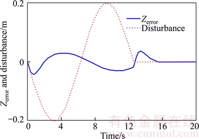
Figure 8 Disturbance rejection test results
4.3 Noise attenuation test
A zero mean white Gaussian noise is generated with a frequency of 100 Hz and peak amplitude of +0.02 as shown in Figure 9(a). The generated noise is then fed into the feedback loop for both the position and orientation to simulate sensor noise. The quadcopter is assumed to be hovering at 1 m before applying the sensor noise. The maximum drift in the quadcopter position and orientation are in the range of ��3��10�C3m and ��2��10�C3 (��), respectively as shown in Figures 9(b) and (c).
Again, the controller shows a good noise attenuation capability as expected from the singular value plot for the T function at high frequencies.
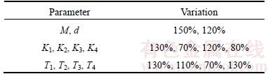
4.4 Robustness to model parameters uncertainties
In this test, the quadcopter model parameters are changed, as shown in Table 1.
The same step input test in Section 4.1 is applied again to the system with these uncertainties. The simulation results shown in Figure 10 reveal the effectiveness of the controller and the feedback linearization technique in occupying these uncertainties in the model parameters.
4.5 Flight scenario
As a trajectory tracking test, we assume that the quadcopter is hovering at a height of 1 m and it should follow a horizontal butterfly like shape trajectory. While it follows the position trajectories, it should keep its body levelled which is impossible for traditional quadcopters to do.
The desired position is expressed as:
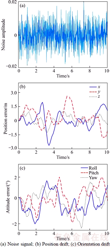
Figure 9 Noise attenuation test results:
Table 1 Variation of model parameters
 (42)
(42)
where ��(t)=0.5�C0.25cos(0.2t).
Figure 11(a) represents the desired 3D position profile. The simulation results show that the maximum error in position is about 2 cm while the maximum drift in the orientation is almost 0 rad. Figures 11(b) and (c) exhibit the results of this flight scenario.
The other important quantities are:
1) The peak linear velocity of the quadcopter body is 0.155 m/s;
2) The maximum linear acceleration during the path following is 0.087 m/s2.
5 Conclusions
A robust controller design for an overactuated quadcopter is addressed. As we have seen, QTRcopter has the ability to control its position and attitude independently. On the contrary, the traditional quadcopter UAVs have a limitation in trajectory tracking due to its underactuation problem.
The mathematical model derived in this work can be used as a base for the exploration of other control methods.
The input-output linearization method has been used to address the nonlinearities in the system dynamics at the purpose of using a linear control method. The designed linear controller is robust and capable of dissolving the effect of the uncertainties in model parameters. It also has the ability of rejecting external disturbance, and attenuating the sensor noise.
Five simulation tests have been made to explore the ability of our proposed controller and the overactuated quadcopter design. The simulation results show excellent controllability and accurate tracking of complicated maneuvers and illustrate the QTRcopter superiority over the standard one.
Appendix
Abbreviations and their definitions
Symbol
Description
FE
Earth frame
FB
Quadcopter body frame
FSi
ith servo frame
FPi
ith rotor group frame
SiRPi
Rotation matrix from FPi to FSi
BRSi
Rotation matrix from FSi to FB
ERB
Rotation matrix from FB to FE
Rx(��x)
Rotation matrix around x-axis with angle ��x
Ry(��y)
Rotation matrix around y-axis with angle ��y
Rz(��z)
Rotation matrix around z-axis with angle ��z
��i
ith rotor group tilt angle
FPi
Force vector generated by rotor group i
Ki
ith propeller thrust factor
��i
ith propeller spinning speed
FTR
Total generated thrust of the four rotor groups
Fg
Gravitational force
g
Gravitational constant
FT
Total force acting on the quadcopter
��Pi
Torque vector generated by rotor group i
LB��Pi
A vector from the origin of FB to the origin of FPi
��Di
Drag torque vector of rotor group i
��Ri
Reactive torque vector of rotor group i
d
Center to center distance between FB and FPi
Ti
ith propeller drag factor
��T
Total generated torque of the four rotor groups
M
Quadcopter total mass
��B
Quadcopter body angular velocity [p, q, r]T
vB
Quadcopter body linear velocity [vx, vy, vz]T
I
Moment of inertia of quadcopter
A
Quadcopter attitude [f, ��, ��]T
P
Quadcopter position [x, y, z]T
Ad
Desired quadcopter attitude [fd, ��d, ��d]T
Pd
Desired quadcopter position [xd, yd, zd]T
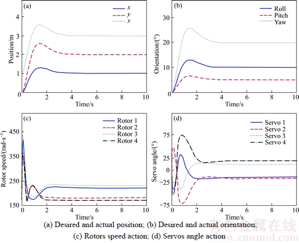
Figure 10 Model parameters uncertainty test results:
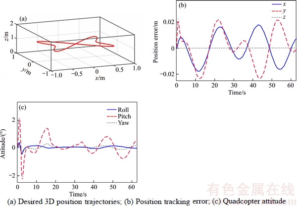
Figure 11 Result of flight scenario:
References
[1] YEO H, JOHNSON W. Performance and design investigation of heavy lift tilt-rotor with aerodynamic interference effects [J]. Journal of Aircraft, 2009, 46(4): 1231�C1239.
[2] ETINSOY E, DIKYAR S, HANER C, ONER K T, SIRIMOGLU E, UNEL M, AKSIT M F. Design and construction of a novel quad tilt-wing UAV [J]. Mechatronics, 2012, 22(6): 723�C745.
[3] JEONG S H, JUNG S. Novel design and position control of an omni-directional flying automobile (Omni-flymobile) [C]// IEEE International Conference on Control Automation and Systems (ICCAS): 2010: 2480�C2484.
[4] KENDOUL F, FANTONI I, LOZANO R. Modeling and control of a small autonomous aircraft having two tilting rotors [C]// 44th IEEE Conference on Decision and Control. 2005: 8144�C8149.
[5]  NER K T, ETINSOY E,
  NEL M, AKIT M F, KANDEMIR I, GLEZ K.Dynamic model and control of a new quadrotor unmanned aerial vehicle with tilt-wing mechanism [J]. World Academy of Science, Engineering and Technology, 2008, 2(9): 58�C63.
[6] SANCHEZ A, ESCARENO J, GARCIA O, LOZANO R. Autonomous hovering of a noncyclic tiltrotor UAV: Modeling, control and implementation [C]// 7th IFAC World Congress. 2008, 41(2): 803�C808.
[7] MOHAMED M K, LANZON A. Design and control of novel tri-rotor UAV [C]// UKACC International Conference on Control. Cardiff, 2012: 304�C309.
[8] RYLL M, BULTHOFF H H, GIORDANO P R. A novel overactuated quadrotor unmanned aerial vehicle: Modeling, control, and experimental validation [J]. IEEE Transactions on Control Systems Technology, 2015, 23(2): 540�C556.
[9] NALDI R, MARCONI L, MARCONI L. Modeling and control of the interaction between flying robots and the environment [C]// 8th IFAC Symposium on Nonlinear Control Systems. 2010, 43(14): 975�C980.
[10] MARCONI L, NALDI R, GENTILI L. Modelling and control of a flying robot interacting with the environment [J]. Automatica, 2011, 47(12): 2571�C2583.
[11] ENKUL F, ALTU E. Modeling and control of a novel tilt��Roll rotor quadrotor UAV [C]// Int Conf on Unmanned Aircraft Systems (ICUAS). 2013: 1071�C1076.
[12] ELFEKY M, ELSHAFEI M, SAIF A W, AL-MALKI M F.Quadrotor helicopter with tilting rotors: Modeling and simulation [C]// World Congress on Computer and Information Technology (WCCIT). 2013: 1�C5.
[13] GUPTE S, MOHANDAS P I T, CONRAD J M. A survey of quadrotor unmanned aerial vehicles [C]// Proceedings of IEEE. Southeastcon, Orlando, FL, USA. 2012: 1�C6.
[14] ERGINER B B, ALTU E. Modeling and PD control of a quadrotor VTOL vehicle [C]// IEEE Intelligent Vehicles Symposium. 2007: 894�C899.
[15] KHATOON S, SHAHID M, CHAUDHARY H, KHATOON S, SHAHID M, CHAUDHARY H. Dynamic modeling and stabilization of quadrotor using PID controller [C]// Int Conf on Advances in Computing, Communications and Informatics (ICACCI). New Delhi, 2014: 746�C750.
[16] NICOL C C, MACNAB J B, RAMIREZ-SERRANO A. Robust neural network control of a quadrotor helicopter [C]// Canadian Conf on Electrical and Computer Engineering. 2008: 1233�C1238.
[17] ZHANG X, LI X, WANG K, LU Y. A Survey of Modelling and Identification of Quadrotor Robot [J]. Abstract and Applied Analysis, 2014, Article ID 320526.
[18] NEMATI A, KUMAR M. Modeling and control of a single axis tilting quadcopter [C]// American Control Conf (ACC). 2014: 3077�C3082.
[19] BAYRAKCEKEN M K, YALCIN M K, ARISOY A, KARAMANCIOGLU A.HIL simulation setup for attitude control of a quadrotor [C]// IEEE Int Conf on Mechatronics (ICM). 2011: 354�C357.
[20] KHORANI V, AJILFOROUSHAN N, SHAHRI A M. An IMU-based system identification technique for quadrotors [C]// IEEE 3rd Joint Conf on AI & Robotics and 5th RoboCup Iran Open International Symposium (RIOS). 2013: 1�C6.
[21] STINGU E, LEWIS F. Design and implementation of a structured flight controller for a 6DoF quadrotor using quaternions [C]// 17th Mediterranean Conf on Control and Automation. 2009: 1233�C1238.
[22] SALIH A L, MOGHAVVEMI M, MOHAMED H A, GAEID K S. Modelling and PID controller design for a quadrotor unmanned air vehicle [C]// IEEE Int Conf on Automation Quality and Testing Robotics (AQTR). 2010: 1�C5.
[23] BOUABDALLAH S, NOTH A, SIEGWART R. PID vs LQ control techniques applied to an indoor micro quadrotor [C]// IEEE/RSJ Int Conf on Intelligent Robots and Systems (IROS 2004). 2004, 3: 2451�C2456.
[24] FERNANDO H C, DE SILVA A T, DE ZOYSA M D, DILSHAN K A, MUNASINGHE S R.Modelling, simulation and implementation of a quadrotor UAV [C]// 8th IEEE Int Conf on Industrial and Information Systems (ICIIS). 2013: 207�C212.
[25] MAHONY R, KUMAR V, CORKE P. Multirotor Aerial Vehicles: Modeling, estimation, and control of quadrotor [J]. IEEE Robotics and Automation Magazine, 2012, 19(3): 20�C32.
[26] PHILLIPS W F. Mechanics of Flight [M]. Wiley and Sons Inc., 2004.
[27] STEPNIEWSKI W Z, KEYS C N. Rotory-wing aerodynamics [M]. Dover Publications Inc., 1984.
[28] HAMANO F. Derivative of rotation matrix �C direct matrix derivation of well-known formula [C]// Proceedings of Green Energy and Systems Conference, 2013, arXiv preprint arXiv:1311.6010.
[29] SLOTINE J J E, LI W P. Applied nonlinear control [M]. Englewood Cliffs, NJ: Prentice-Hall, 1991.
[30] ACKERMANN J. Robust control: The parameter space approach [M]. Springer Science & Business Media, 2012.
[31] ZAMES G. Feedback and optimal sensitivity: Model reference transformations, multiplicative seminorms, and approximate inverses [J]. IEEE Trans Automat Control, 1981, 26(2): 301�C320.
[32] STOORVOGEL A. The H�� control problem: A state space approach [M]. Prentice Hall, 1992.
[33] ATHANI V V, AGARWAI S. Design of a robust controller for a supersonic aircraft using H�� approach [J]. Control Engineering Practice, 1994, 2(6): 1051�C1061.
[34] BANAVAR R N, DOMINIC P. An LQG/H�� controller for a flexible manipulator [J]. IEEE Trans Control Systems Technology, 1995, 3(4): 409�C416.
[35] YAN J, SALCUDEAN S E. Teleoperation controller design using H�� optimization with application to motion scaling [J]. IEEE Trans Control System Technology, 1996, 4(3): 244�C258.
[36] SAFONOV M G, CURTAIN R F. Imaginary-axis zeros in multivariable H��-optimal control [M]. Berlin Heidelberg: Springer, 1987.
[37] CHIANG R Y, SAFONOV M G. MATLAB Computation visualization programming user��s guide [M]. Natick, Massachusetts, USA: The Math Works Inc, 2005.
[38] XUE D, CHEN Y Q, ATHERTON D. Linear feedback control: Analysis and design with MATLAB [M]. SIAM Press, 2007.
[39] POSTLETHWAITE I, O��YOUNG S D, GU D W, HOPE J. H�� control system design: A critical assessment based on industrial applications [C]// IFAC 10th World Congress on Auto Control. Munich, 1987, 8: 328�C333.
[40] POSTLETHWAITE I, TSAI M C, GU D W. Weighting function selection in H�� design [C]// IFAC 11th Triennial World Congress, Automatic Control. 1990: 127�C132.
(Edited by FANG Jing-hua)
���ĵ���
����ʽ��бת�������������H������
ժҪ�������������˻��ھ��¡���ѧ����������Ӧ�ù㷺������������Խ��Խ�����Ȥ����������ȱ����ֵ��������ԣ������������ƶ��Ժ켣�������������Ľ�����һ�ֹ����������������ƺͿ��ƣ���������ת��Χ������������б��������ڻ���ͨ����ó�ֵ����غ���ʸ�����˷������Ļ��������ơ���б����ʹ�����������ӵ�8��(4��������ת�ټ�4��ת����б��)��ʹ���������������ȫ����״̬������Newton-Euler�������Ƶ�����ת����б����������Ĺ㷺��ѧģ�ͣ��������˷������Ի��������������Ի�������ģ�ͽ������Ի�����ƺϳ�һ�ֻ��������H�����ſ��������Դﵽ��������ܺ��ȶ��ԡ��Կ���ϵͳ�����˷��棬�Ա�֤�������������������Ƶ���Ч�ԡ������˸ÿ����������Ƹ��š����ƴ����������ʹ���ģ�Ͳ�ȷ���ȷ�������ܣ������临�ӹ켣���������飬�����������������������ڴ�ͳ�������������
�ؼ��ʣ��������Ի���H���Ϳ�������Newton-Euler�������������������³������
Received date: 2016-12-13; Accepted date: 2017-03-23
Corresponding author: Ahmed ALKAMACHI, PhD, Lecturer; Tel: +96�C47702370600; E-mail: amrk1978@gmail.com; ORCID: 0000- 0001-9822-6179
Abstract: In recent years, unmanned aerial vehicles (UAVs) have acquired an increasing interest due to their wide range of applications in military, scientific, and civilian fields. One of the quadcopter limitations is its lack of full actuation property which limits its mobility and trajectory tracking capabilities. In this work, an overactuated quadcopter design and control, which allows independent tilting of the rotors around their arm axis, is presented. Quadcopter with this added tilting mechanism makes it possible to overcome the aforementioned mobility limitation by achieving full authority on torque and force vectoring. The tilting property increases the control inputs to 8 (the 4 propeller rotation speed plus the 4 rotor tilting angles) which gives a full control on the quadcopter states. Extensive mathematical model for the tilt rotor quadcopter is derived based on the Newton-Euler method. Furthermore, the feedback linearization method is used to linearize the model and a mixed sensitivity H�� optimal controller is then designed and synthesized to achieve the required performance and stability. The controlled system is simulated to assure the validity of the proposed controller and the quadcopter design. The controller is tested for its effectiveness in rejecting disturbances, attenuating sensor noise, and coping with the model uncertainties. Moreover, a complicated trajectory is examined in which the tilt rotor quadcopter has been successfully followed. The test results show the supremacy of the overactuated quadcopter over the traditional one.
