
Article ID: 1003-6326(2005)02-0457-03
Finite element analysis of stresses and interface crack in TBC systems
CHEN Xiao-mei(����÷), ZHANG Yue(�� Ծ), GONG Sheng-kai(������)
(
Abstract:
Thermal barrier coatings have been used on high temperature components. Due to high stresses leading to unpredictable failure, a transient thermal-structural finite element solution was employed to analyze the stress distribution and J-integral at the interface between the bond coating and thermally growing oxide(TGO) in the EB-PVD thermal barrier coatings subjected to thermal loadings. The effects of some environmental and material parameters were studied, such as thermal convection coefficient, ceramic elastic modulus and TGO thickness. The results show that the stresses and J-integral values are impacted by these parameters.
Key words:
thermal barrier coatings; finite element method; stress; crack; J-integral CLC number: TG17;
Document code: A
1 INTRODUCTION
The high performance engine demands high thrust-to-mass ratio and high pressure. One of the adopted approaches is to increase the inlet temperature of the turbine or the temperature of the combustion chamber. Thermal barrier coatings have been developed based on these demands. The typical thermal barrier coatings are double layer systems composed of the bond coating and ceramic coating. The MCrAlY alloy is used as the bond coating. It is used to improve the physical compatibility between the ceramic coating and the metal substrate and also to resist oxidation of the substrate. The ceramic coating material usually prefers ZrO2 with 6%-8%Y2O3(mass fraction).
Failure of thermal barrier coatings is crucial for their usage, which results from the thermally growing oxide(TGO) and thermal stresses[1]. The stresses are considered a control factor. The stresses produced in TBCs include four kinds: thermal stresses caused by temperature filed distribution and thermal stresses caused by the thermal expansion mismatch, which are two basic thermal stresses, thermal growth stresses generated in thermal growing oxidation of the metallic bond coating and phase transition stresses[2]. When the thermal stresses are larger than the combination strength, crack forms. The stresses produced during the thermal cyclic process result in the crack propagation finally leading to cracks large enough to cause spallation of the top coating[3]. Therefore the stress is the main reason for the thermal barrier coatings failure.
The factors impacting on stresses include the difference of thermophysical properties between ceramic and metal, the characteristics of coatings and their environment. The stress tends to generate in the fast cooling period of the thermal cycle[4], where cooling rate is an important factor. On the other hand, coatings structure changes during the thermal cycles because of TGO generation and growth between the ceramic coating and bond coating, which affects the stress seriously[5]. Otherwise, ZrO2 is columnar crystal in coatings prepared by EB-PVD method, whose elastic modulus is much lower than that of the bulk ceramics. The elastic modulus of the ceramic layer will increase because of sintering during thermal cycle, and this kind of change will lead to stress change.
Thermal barrier coatings failure usually begins with the crack initiation and crack propagation. And the crack tends to generate at the interface between TGO and bond coating. Previous investigations[5-7] show that in order to predict fracture in the bimaterial specimen, the stress intensity factor must be determined, and the following methods can be adopted[8]: 1) the use of crack flank displacement data; 2) the use of the J-integral; 3) the use of the local collocation technique applied to stress field data.
J-integral has been adopted by most current structural integral estimation procedures of cracked bodies under combined secondary and primary loadings[9]. J-integral is a typical nonlinear fracture mechanics parameter expressing the stress/strain intensity of a crack[10]. Recently, a path-independent J-integral for residual stress and the combination of residual stress and mechanical loading has been developed by Lei et al[9], which enables the J-integral for crack in a residual stress field to be evaluated accurately.
2 MODEL AND CALCULATION
In this paper, finite element method(ANSYS 7.0) is used to analyze the stress and thermal distribution in thermal barrier coatings. The model includes four layers (as shown in Fig.1): the substrate (
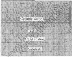
Fig.1 Thermal barrier coatings model
3 RESULTS AND DISCUSSION
The influence of thermal convection coefficient on J-integral at the pre-crack tip and delamination stress (it is also called normal stress) is shown in Fig.2. The result shows that there is a tensile normal stress at the interface between the TGO and the bond coating, and both the J-integral value and the normal stress increase with increasing the thermal convection coefficient. The results of thermal field analysis show that temperature gradient in the ceramic coating increases as the cooling rate increases[13]. If no temperature gradient is considered during the cooling, the normal stress is compression[14]. The stress changes from compression to tension and increases significantly with the increase of the temperature gradient. Therefore, the cooling rate rather than the temperature difference of the thermal cycle is crucial for crack formation at the interface[15]. The results in the Fig.2 also indicate that crack propagation increases with the increase of the cooling rate because of the increase in the J-integral.
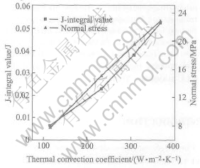
Fig.2 Influence of thermal convection coefficient on J-integral and normal stress
Fig.3 shows the effect of TGO thickness on the normal stresses at the interface. The normal stress increases when TGO thickness increases. The increasing tendency of the stress becomes larger as the thickness increases. TGO is a key factor that affects the material thermophysical properties and perdurable ability of thermal barrier coatings. The main composition of TGO is Al2O3, which has higher thermal expansion coefficient and higher elastic modulus. Therefore, the thermal mismatch increases and the ability of released stress decreases. On the other hand, when the system is cooled, the mismatch of thermal expansion between coatings and the substrate will induce the residual stress. And the TGO growing also induces stress. Although the stress induced by TGO growing is smaller than that induced by the thermal mismatch, it has obvious effects on material properties. TGO is very thin, but there is very high strain energy density in TGO. All these effects can lead to the material failure. As the result, crack propagation is accelerated by the TGO growth caused by oxidation at high temperature.
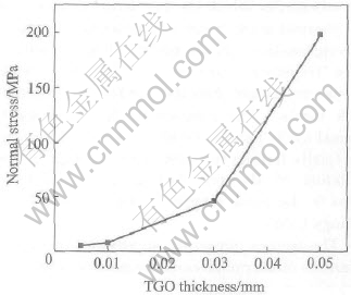
Fig.3 Influence of TGO thickness on normal stress
Fig.4 shows calculation result of the relationship between the elastic modulus of the ceramic coating and the normal stress. The result shows that the normal stress increases with the increase of the modulus. The increase in the modulus represents sintering effect of the ceramic coating with columnar grain. During thermal barrier coatings thermal cycling, in the ceramic coating phase change occurs when temperature increases, and then sintering occurs. Both phase change and sintering can change the volume and mechanical properties of the ceramic coating. After it is sintered, the volume becomes smaller, which makes the stress increase at the interface. So from the result we can see that the sintering of ceramic coating during high temperature results in the remarkable increase in the stress. The effect of sintering is the same as TGO growth.
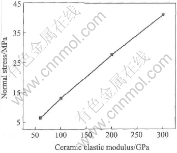
Fig.4 Influence of ceramic elastic modulus on normal stress
4 CONCLUSIONS
During thermal cycle, cooling rate, TGO growth and sintering of ceramic coat significantly influence the normal stress and J-integral at the TGO/bond coating interface. Both the delamination stress and J-integral increase as these three factors increase, and they are crucial for lifetime of TBCs. The results are helpful for clarifing failure mechanism and designing high performance TBCs.
REFERENCES
[1]LIN Feng, JIANG Xian-liang. Research development of the thermal barrier coatings [J]. The Journal of Functional Materials, 2003, 3(34): 254-261.(in Chinese)
[2]
[3]Ahrens M, Va��en R, St��ver D. stress distributions in plasma-sprayed thermal barrier coatings as a function of interface roughness and oxide scale thickness [J]. Surface and Coatings Technology, 2002, 161: 26-35.
[4]ZHANG Yue, WANG Yu-dong, YIN Ke-gang, et al. Finite element analysis of residual stresses in thermal barrier coatings [A]. The 5th International Meeting of
[5]Evans A G, Mumm D R, Hutchinson J W, et al. Mechanisms controlling the durability of thermal barrier coatings [J]. Progress in Materials Science, 2001, 46: 505-553.
[6]Choi S R, Hutchinson J W, Evans A G. Delamination of multilayer thermal barrier coatings [J]. Mechanics of Materials, 1999, 31: 431-447.
[7]ZHANG Yan-Ji, ZHAO
[8]Miller T C, Chona R. Finite element analysis of a thermally loaded interface crack in a ceramic coating [J]. Engineering Fracture Mechanics, 1998, 59(2): 203-214..
[9]Lei Y, O��Dowd N P, Webster G A. Estimation and defect assessment for combined residual stress and mechanical loading [J]. International Journal of Pressure Vessels and Piping, 2000, 77: 321-333.
[10]
[11]Teixeira V, Andritschky M, Fischer W, et al. Effects of deposition temperature and thermal cycling on residual stress state in zirconia-based thermal barrier coatings [J]. Surface and Coatings Technology, 1999, 120-121: 103-111.
[12]Sfar K, Aktaa J, Munz D. Numerical investigation of residual stress fields and crack behavior in TBC systems [J]. Materials Science and Engineering, 2002, A333: 351-360.
[13]Zhang Y, Wang Y, Yin K,et al. Finite element analysis of residual stresses in thermal barrier coatings [J], J Ceram Soc Japan, 2004, 112(5): 1122-1124.
[14]Teixeira V, Andritschky M, Fischer W, et al. Analysis of residual stresses in thermal barrier coatings [J]. Journal of Materials Processing Technology, 1999, 92-93: 209-216.
[15]ZHANG Yue, ZHANG Yan-ji, GU Jing-hua. A computational simulation of interaction between polyelectrolyte and ceramic particles [J]. Key Engineering Materials, 2001, 224-226: 697-701.
Received date:
Correspondence: ZHANG Yue, Professor, PhD; E-mail: zhangy@buaa.edu.cn
