
J. Cent. South Univ. Technol. (2009) 16: 0774-0780
DOI: 10.1007/s11771-009-0129-9
![]()
Numerical simulation method for weld line development in micro injection molding process
XIE Lei(л ��)1, ZIEGMANN Gerhard1, JIANG Bing-yan(������)2
(1. Institute of Polymer Materials and Plastics Engineering, Clausthal University of Technology,
Agricola Str.6, Clausthal-Zellerfeld 38678, Germany;
2. Key Laboratory of Modern Complex Equipment Design and Extreme Manufacturing, Ministry of Education,
Central South University, Changsha 410083, China)
Abstract:
In order to reduce the ��trial-mold�� risk and cost, numerical simulation method was applied to micro injection molding weld line development investigation. The micro tensile specimen which has the size of 0.1 mm (depth)��0.4 mm (width)��12 mm(length) in test area was selected as the objective part, and polypropylene (PP) as the experimental material. Respectively with specific commercial software (Mold Flow?) and general computational fluid dynamic (CFD) software (Comsol? Multiphysics), the simulation experiments for development of weld line in micro injection molding process were executed and the real comparison experiments were also carried out. The results show that during micro injection molding process, the specific commercial software for normal injection molding process is not valid to describe the micro flow process, the shape of flow front in micro cavity flowing which is important in weld line developing study and the contact angle due to surface tension are not able to be simulated. In order to improve the simulation results for micro weld line development, the general CFD software, which is more flexible in user defining function, is applied. The results show better effects in describing micro fluid flow behavior. As a conclusion, as for weld line forming process, the numerical simulation method can give a characteristic analysis results for processing parameters optimizing in micro injection molding process; but for both kinds of softwares quantitative analysis cannot be obtained unless the boundary condition and micro fluid mathematic model are improved in the future.
Key words:
weld line; micro injection molding; numerical simulation��
1 Introduction
As a novel fabrication technology, micro technology is paid much attention all over the world [1-2]. Weld line is a usual but unfavorable flaw in normal and micro injection molding processes. Therefore, it is important for improving the quality of injection molding parts so that the weld line developing theory is understood completely [3-5]. Nowadays, the weld line phenomenon in normal injection molding field has been studied maturely, but as for micro injection molding, the concentration on weld line study is not adequate.
As for the research methods of weld line development, the numerical simulation method is widely used to study weld line position and developing in normal injection molding process. NGUYEN-CHUNG [6] presented a non-isothermal simulation of the weld line formation due to collision of two flow fronts. In this way the sources of the weld line weakness and their interrelationship can be investigated with regard to the flow history and the thermo rheological situation, which as a whole enables a better understanding of the mechanisms of the weld line formation. DIARANIEH et al [7] discussed the sensitivity of Moldflow? weld line prediction algorithm to variations of materials property and variations of processing conditions, and demonstrated that the average viscosity can be potentially used to predict the strength in regions influenced by weld line. NGUYEN-CHUNG et al [8] investigated the flow disturbance in polymer melt behind an obstacle and simulated this process by FIDAP?, and those results are consistent to Moldflow? results and experiments. Up to now, a number of commercial simulation softwares are available for predicting the position of the weld line, such as Moldflow?, C-Mold?, CADMOULD? and SIGMASOFT?, but these softwares do not consider the detailed information in advancing
melt front, such as fountain flow, surface tension and wall slip phenomena [9-12]. In addition, some researchers indeed developed their home-made finite element method (FEM) 3 dimensional software to better consider specific conditions of the micro injection process, with flow front tracking methods such as pseudo-concentration, volume of fluid (VOF) or level-set method [13-16].
However, due to the inadequate understanding for micro fluid dynamics, these methods are usually not applied to investigation of weld line development as traditional injection molding research. In this work, a cold weld line developing process in micro injection molding was considered mainly by numerical simulation method. And the real comparison experiments were also carried out.
2 Simulation and experiment
2.1 Specimen geometry and dimension
The specimen is a micro scale tensile test part. The geometry and dimension of the specimen are illustrated in Fig.1.
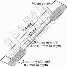
Fig.1 Geometry and dimensions of specimen
The whole length is 24 mm and the length of test area is 12 mm. The cross section shape is rectangular with dimensions of 0.1 mm (depth)��0.4 mm (width).
2.2 Mold Flow? simulation
First, the simulation was carried out by commercial software MoldFlow MPI5.0?, which simulated the viscous filling phase during micro injection molding for the cavity (shown in Fig.1) from two ends. The mass, momentum and energy equation are described as follows:
![]() (1)
(1)
![]()
![]() (2a)
(2a)
![]()
![]() (2b)
(2b)
![]()
![]() (2c)
(2c)
![]()
![]() (3)
(3)
 (4)
(4)
where x, y and z are the Cartesian coordinates, t is the time, �� is the density, u, v and w are the velocities in x, y and z directions, p is the pressure, g is the acceleration of gravity, �� is the viscosity, �� is the coefficient related to heat transfer, H is the enthalpy, and ![]() is the shear rate.
is the shear rate.
Cross-WLF viscosity model is used to describe the rheological behavior of polymer materials. The viscosity model is written as follows:
![]() (5)
(5)
where ![]() , T��T*; ��0(T,
, T��T*; ��0(T,
p)=��, T��T*; T*(p)=D2+D3p; A1=A2+D3p; T* is the glass transition temperature; n is flow index.
The whole calculation field is meshed as 115 172 tetrahedron elements, and the material is Polyproplene (PP, DOW Euro GmbH). The virtual simulation experimental plan is listed in Table 1.
2.3 Mold flow simulation results analysis
According to the simulation results by MoldFlow MPI (shown in Fig.2), it can be figured that when the mold temperature is not high enough (lower than 120 ��), the micro specimen cavity cannot be fully filled, even if the highest injection pressure (250 MPa) is used. That is because of the fast freezing for polymer melts flowing in micro scale cavity. But when the mold temperature reaches 120 ��, even in relatively lower injection pressure, the complete filled specimen can still be produced. The results are also verified by the real injection molding experiments. The initial testing ��short-shot�� and complete filled specimens are shown in Fig.3. Comparing the simulation results in Fig.2(c) with the real experiment parts in Fig.3(a), it can be found that they are fit for each other characteristically quite well.
However, in weld line developing study, the flow front shape is important for the joint of two fronts in weld line area, which is a significant factor for evaluating mechanical property of weld line. By comparison between the MoldFlow simulation results
Table 1 Virtual simulation experimental parameters
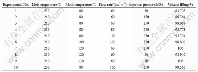
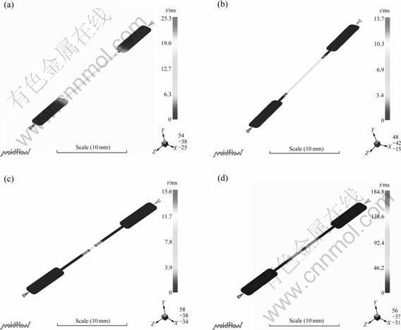
Fig.2 Filling simulation results under different processing conditions: (a) Melt temperature 210 ��, mold temperature 80 ��, flow rate 60 cm3/s, injection pressure 50 MPa; (b) Melt temperature 210 ��, mold temperature 80 ��, flow rate 60 cm3/s, injection pressure 150 MPa; (c) Melt temperature 210 ��, mold temperature 80 ��, flow rate 60 cm3/s, injection pressure 250 MPa; (d) Melt temperature 210 ��, mold temperature 130 ��, flow rate 60 cm3/s, injection pressure 50 MPa
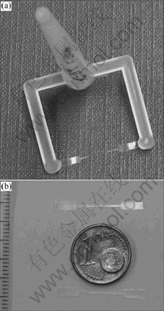
Fig.3 Experiments under different conditions: (a) Melt temperature 210 ��, mold temperature 80 ��, flow rate 60 cm3/s, injection pressure 250 MPa; (b) Melt temperature 210 ��, mold temperature 130 ��, flow rate 100 cm3/s, injection pressure 250 MPa
and the real experimental results, it can be concluded that MoldFlow? MPI cannot give a precise simulation for the flow front shape in micro scale, as shown in Fig.4. And as a reason for influencing the flow front shape, the surface tension is also ignored in MPI. So the MPI can act as a characteristic part for assisting micro injection molding processing optimization, but not suitable for the weld line developing investigation in micro injection molding due to its ignorance in micro fluid dynamic features.
3 Comsol? Multiphysics simulation
The simulation considered surface tension and focused on description of micro flow front shape was worked out by a general commercial finite element method (FEM) code Comsol? Multiphysics 3.4. The mathematic model considered micro fluid dynamic and two-phase level-set method (Control Volume Method) was used in this work to simulate the development of
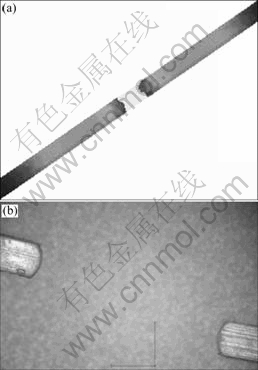
Fig.4 Flow front shape in micro channel simulated with MoldFlow? MPI (a), and real appearance of flow front shape in micro channel obtained by manual short-shot experiment (b)
weld line in micro dimension geometry. The government equations used in the simulation by Comsol Multiphysics 3.4 are generally same as those by Mold Flow software, which are listed in section 2.2. However, here the heat transfer is not calculated, so the energy equation in section 2.2 is not applied. While considering the surface tension effect, the mass and momentum transport equations have a new description.
![]() (7)
(7)
where u represents the velocity vector, I is the identity matrix, g is the gravity vector, and Fst is the surface tension force.
The boundary conditions used in this simulation are described in Fig.5. The simulation filling processes without heat transfer coupling are presented in Fig.6. The surface tension effect, which could be an influencing factor for flow front shape in micro scale, is considered
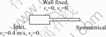
Fig.5 Boundary conditions setting during Comsol simulation
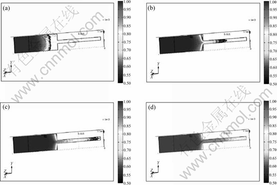
Fig.6 Flow front tracing simulation results for weld line developing process in micro injection molding with Comsol? Multiphysics 3.4 at different time steps (legend scale is volume fraction of polymer melts; unit of geometry dimension scale is m): (a) t=30 ms; (b) t=45 ms; (c) t=50 ms; (d) t=55 ms
during the simulation and calculated by Eqs.(8)-(10) during the simulation, which is regarded as wetted wall condition. In the Level Set application mode the surface tension force is computed as
![]() (8)
(8)
T=��(I-(nnT))�� (9)
where n is the interface normal, �� equals the surface tension coefficient (N/m), and �� equals a Dirac delta function that is nonzero only at the fluid interface. When the finite element method is used to solve the Navier-Stokes equations, the equations will be multiplied by test functions and then integrated over the computational domain. If the integration by parts is used, derivatives of T can be moved to the test functions. This is used in the Level Set and Laminar Flow application mode and results in an integral over the computational domain plus a boundary integral of the form
![]() (10)
(10)
where �� is the contact angle. If a no-slip boundary condition is applied, the boundary term will vanish because test(u)=0 on that boundary, and the contact angle cannot be specified. Instead, the interface remains fixed on the wall. However, if a small amount of slip is applied, it is possible to specify the contact angle. The wetted wall boundary condition adds the term given by Eq.(8) and consequently makes it possible to set the contact angle. During simulation, the initial contact angle is set as 60? and the surface tension coefficient �� is set as 0.3 N/m.
From Fig.6, it can be found that Comsol Multiphysics is able to describe the filling process as well. However, the shape of the fluid flow front in the micro scale phase is not predicted as expected as smooth arc curve. The results show the volume fraction of two fluids (one is PP melt, the other is air), during the filling in micro channel. And the polymer melt flow front is separated and mixed with air, as illustrated in Fig.6. Even this interesting phenomenon is not expected, the similar situation is observed in the real experimental samples, as shown in Fig.7. But it is still not clear that the non-transparent ��bubbles�� around the weld line formation area where two flow fronts encounter are air or not, which needs to be further proved and investigated in the next step by micro cutter machine and high magnification polarized microscope. Then this sample was cut by microtrom (Karl Zeiss?), and observed under scanning electronic microscope (SEM). Based on the photo by SEM, it can be found that there are several tiny hollow cavities inner the sample, which means the non-
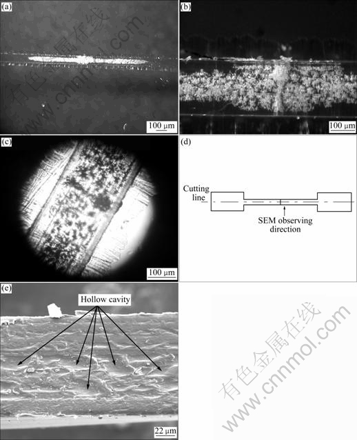
Fig.7 Non-transparent ��bubbles�� around area where two flow fronts encountered (weld line area) observed by optical microscope with different magnifications ((a) and (b)), and by polarized microscope (c), micro cutting direction and SEM observing direction (d) and SEM image of sample prepared by micro cutter (e)
transparent bubbles observed before are air. The reason why those air bubbles appeared is that during the micro injection molding process, the air between the two flow fronts is not vented in time, then embedded and mixed into the polymer melts.
4 Conclusions
(1) MPI has a good performance for processing parameter optimization. It can give good characteristic simulation results, which are helpful for researcher to obtain the initial information about the parameters setting and mold design before the real micro injection molding experiment. However, for the shape of flow front of micro fluid filling process, MPI cannot function well and the proceeding detail of two flow fronts encountering is not figured out.
(2) Comsol Multiphysics has micro electronic mechanical system (MEMS) model for micro fluid specially and can consider the surface tension during the simulation for micro weld line forming. The shape of the fluid in micro channel is still not pictured perfectly.
(3) One interesting aspect of Comsol simulation results is observed, that is, the polymer melt flow front is separated and mixed with air, and the similar situation is also observed in the real experimental samples by polarized microscope and SEM. But in order to prove the correction of simulation results about it, further investigation must be carried out in the next step. Furthermore, there should be more possibility to improve the simulation performance of Comsol through correcting boundary condition more closely to reality and coupling heat transfer model during filling simulation.
References
[1] MICHAELI W, ROALLA A, SPENNEMANN A, ZIEGMANN C. Micro-structured parts made of plastics[J]. F&M Fine Engineering, Microtechnology, Microelektronik, 1998, 9: 642-645. (in German)
[2] PIOTTER V, BAUER W, BENZLER T, EMDE A. Injection molding of components for microsystems [J]. Microsystems Technologies, 2001, 7(3): 99-102.
[3] XIE L, ZIEGMANN G. A visual mold with variotherm system for weld line study in micro injection molding [J]. Microsystem Technologies, 2008, 14(6): 804-809.
[4] WU Cheng-hsien, LIANG Wan-jung. Effects of geometry and injection-molding parameters on weld line strength [J]. Polymer Engineering and Science, 2005, 45(7): 1022-1030.
[5] MCKLINE G H, RODD L E, OLIVERIRA M S N, COPPER-WHITE J. Extensional flows of polymer solutions in microfluidic converging/diverging geometries [J]. Journal of Central South University of Technology, 2007, 14(S1): 6-9.
[6] NGUYEN-CHUNG T. Flow analysis of the weld line formation during injection mold filling of thermoplastics [J]. Rheol Acta, 2004, 43(3): 240-245.
[7] DIARANIEH I S, HAUFE A, WOLF H J, MENNIG G. Computer simulation of weld lines in injection molded poly(methyl methacrylate) [J]. Polymer Engineering and Science, 1996, 36(15): 2050-2057.
[8] NGUYEN-CHUNG T, PLICHTA C, MENNIG G. Flow disturbance in polymer melt behind an obstacle [J]. Rheol Acta, 1998, 37(3): 299-305.
[9] PIOTTER V, MUELLER K, PLEWA K, RUPRECHT R, HAUSSELT J. Performance and simulation of thermoplastics micro injection molding [J]. Microsystem Technologies, 2002, 8(6): 387-390.
[10] YAO D, KIM B. Simulation of the filling process in micro channels for polymeric materials [J]. Micromech Microeng, 2002, 12(5): 604-610.
[11] SHENA S C, PANB C T, WANGA Y R, CHANGB C C. Fabrication of integrated nozzle plates for inkjet print head using micro injection process [J]. Microsystem Technologies, 2006, 12(2): 241-247.
[12] WORGULL M, HECKELE M.New aspects of simulation in hot embossing [J]. Microsystem Technologies, 2004, 10(5): 432-437.
[13] KAUZLARI? D, LIENEMANN J, PASTEWKA L, GREINER A, KORVINK JG. Integrated process simulation of primary shaping: Multi scale approaches [J]. Microsystem Technologies, 2008, 14(12): 1789-1796.
[14] NAKAO M, TSUCHIYA K, SADAMITSU T, ICHIKOHARA Y, OHBA T,OOI T. Heat transfer in injection molding for reproduction of sub-micron-sized features [J]. The International Journal of Advanced Manufacturing Technology, 2008, 8(3/4): 426-432.
[15] YOUNG W B.Simulation of the filling process in molding components with micro channels [J]. Microsystem Technologies, 2005, 11(6): 495-500.
[16] YU L, KOH C G, LEE J, KOELLING K W, MADOU M. Experiment investigation and numerical simulation of injection molding with micro-features [J]. Polymer Eng Sci, 2002, 42(5): 871-888.
(Edited by YANG You-ping)
Foundation item: Project(ZI648/13-1) supported by German Research Foundation; Project(D/06/00373) supported by German Academic Exchange Service
Received date: 2008-12-30; Accepted date: 2009-02-24
Corresponding author: XIE Lei, M. Sc.; Tel: +49-5323-722427; E-mail: Lei.Xie@tu-clausthal.de
