

J. Cent. South Univ. (2018) 25: 3075-3084
DOI: https://doi.org/10.1007/s11771-018-3975-5

Microstructure and mechanical properties of dissimilar pinless friction stir spot welded 2A12 aluminum alloy and TC4 titanium alloy joints
YANG Xia-wei(�����)1, FENG Wu-yuan(����Ԩ)1, LI Wen-ya(������)1, CHU Qiang(��ǿ)1,XU Ya-xin(������)1, MA Tie-jun(������)1, WANG Wei-bing(������)2
1. State Key Laboratory of Solidification Processing, Shaanxi Key Laboratory of Friction Welding Technologies, Northwestern Polytechnical University, Xi��an 710072, China;
2. China FSW Center, Beijing 100024, China
 Central South University Press and Springer-Verlag GmbH Germany, part of Springer Nature 2018
Abstract:
The microstructure and mechanical properties of dissimilar pinless friction stir spot welded joint of 2A12 aluminum alloy and TC4 titanium alloy were evaluated. The results show that the joint of Al/Ti dissimilar alloys can be successfully attained through pinless friction stir spot welding (FSSW). The joint can be divided into three zones (SZ, TMAZ and HAZ). The microstructure of joint in Al alloy side changes significantly but it basically has no change in Ti alloy side. At the same rotation speed, the maximum load of welded joints gradually rises with the increase in dwell time. At the same dwell time, the maximum load of the welded joint increases with the increase of the rotational speed. In addition, optimal parameters were obtained in this work, and they are rotation speed of 1500 r/min, plunge speed of 30 mm/min, plunge depth of 0.3 mm and dwell time of 15 s. The fracture mode of welded joints is interfacial shear fracture. The microhardness of the joint on the Al side distributes in a typical ��W�� type and is symmetry along the weld center, but the distribution of the microhardness on the Ti side has no obvious change.
Key words:
microstructure; mechanical properties; friction stir spot welded; dissimilar joints��
Cite this article as:
YANG Xia-wei, FENG Wu-yuan, LI Wen-ya, CHU Qiang, XU Ya-xin, MA Tie-jun, WANG Wei-bing. Microstructure and mechanical properties of dissimilar pinless friction stir spot welded 2A12 aluminum alloy and TC4 titanium alloy joints [J]. Journal of Central South University, 2018, 25(12): 3075�C3084.
DOI:https://dx.doi.org/https://doi.org/10.1007/s11771-018-3975-51 Introduction
Aluminium alloys have been widely used in automotive, aerospace and electronic industries due to their strength, good formability and weight savings [1]. 2A12 as a kind of typical hard aluminum alloy, is widely used in industrial fields [2, 3]. TC4 (Ti-6Al-4V) is one of the most widely used (��+��) titanium alloys [4�C7]. A composite component produced by joining these two alloys can maximize the use of their advantages and can be used in many industrial fields. However, the differences of melting point, thermal expansion coefficient, thermal conductivity, etc., between the two alloys are evident. Besides, titanium alloy has higher strength than aluminum alloy at elevated temperatures. Therefore, it is difficult to obtain a satisfied joint by the conventional welding methods such as welding, soldering and diffusion bonding which often accompanied by high temperature oxidation, element deletion, pore and crack, etc. It is very important to solve the joining problem of the two materials for scientific significance and engineering value.
Several different processes, including laser welding, RSW, SPR, friction stir welding (FSW) and adhesive bonding, have been used by manufacturers to joint dissimilar metals [8]. Resistance spot welding (RSW) is a process in which contacting metal surfaces are joined by the heat obtained from resistance to electric current [9, 10]. Using this process, workpieces are held together under pressure exerted by electrodes. But it cannot be used for most cases of dissimilar metals joining, and self-piercing riveting (SPR) has limitations when material ductility is low and strength is very high [8]. In addition, the disadvantages of RSW and SPR methods are higher electric power source, high energy consumption, high cost and low production efficiency for riveting, and large deformation for resistance spot welding [11].
However, in the past few years, rapid development in the applications of dissimilar material friction stir welding (FSW) has taken place in the aerospace and automotive industries, which can eliminate mechanical fastening such as riveted or bolted joints and can reduce the weight of structures greatly [12�C14]. FSW is an efficient method and has been extensively developed for aluminum alloys and other metal materials, and it is an innovative joining technique for the flexibility design and environmental protection [15, 16]. In addition, previous work has shown that FSW is a viable method for spot joining of various combinations of advanced high strength steel (AHSS) and light metals [17].
Pinless friction stir spot welding (pinless FSSW) is a FSSW process invented by Bakavos and Prangnell in 2009 [18�C20]. It has been verified by experiments that the welding process effectiveness in the sheet has a significant advantage in overcoming the problem of large differences in performance of different materials, which can solve the problem of Al/Ti dissimilar metal welding.
In this work, the authors use TC4 titanium alloy and 2A12 aluminum alloy which are commonly used in aerospace structures as the research object, focus on the feasibility of the pinless FSSW process of Al/Ti dissimilar metals, analyze the influence of process parameters on the microstructure and mechanical properties of the joint, and then provide theoretical support for the application of pinless FSSW in the field of welding of Al/Ti dissimilar metals.
2 Experimental
Commercial TC4 titanium alloy and 2A12 aluminum alloy were selected as the raw material. The chemical composition (wt%) of TC4 alloy is given as follows: Fe 0.28, C 0.08, N 0.04, 0.013, 0.18, Al 6.1, V 4.1 and Ti bal. The chemical composition (wt%) of 2A12 alloy is given as follows: Si 0.12, Cu 4.69, Mg 1.60, Mn 0.73, Fe 0.25, Ti 0.10, Zn 0.20, Ni 0.08 and Al bal. Figure 1 shows the pinless FSSW experimental configuration. The materials used in this study are 2 mm thick TC4 titanium alloy and 1.5 mm thick 2A12 aluminum alloy. As show in Figure 1, lap joints are used in spot welding (aluminum plate in the upper, titanium plate in the bottom), and welding position is the geometric center of the lap surface. The pinless tool with diameter of 12 mm was used. The shoulder has three symmetrical long grooves with depth of 0.2 mm which is the involute profile of a 2 mm-radius base circle. The process parameters used in this study are shown in Table 1.
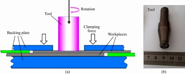
Figure 1 Schematic of pinless FSSW experimental configuration (a) and photo of FSSP tool (b)
Table 1 Process parameters of pinless FSSW
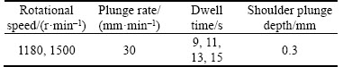
Microstructural analysis of pinless FSSW joints was performed by optical microscopy(OM). Fracture morphology analysis of the joints was performed by scanning electron microscopy(SEM). The specific shape and dimensions of tensile specimens are shown in Figure 2. All the tensile tests were conducted on the SHIMADZU AG-X tensile machine at a strain rate of 1 mm/min.
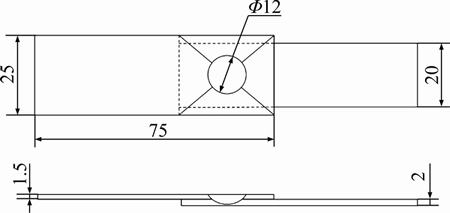
Figure 2 Shape and dimensions of tensile specimens (Unit: mm)
3 Results and discussion
3.1 Microstructure analysis of pinless FSSW joint of Al/Ti
3.1.1 Analysis of microstructure of aluminum side
Figure 3 shows the macroscopic morphology of the cross section of the Al/Ti pinless FSSW joint under different process parameters. It can be seen from Figure 3 that the metallographic structure of the pinless FSSW joint consists of three sections: stir zone (SZ), thermo-mechanically affected zone (TMAZ) and heat affected zone (HAZ), which is similar to the conventional FSW joint. In addition, with the change of process parameters, the morphology of the cross section of the pinless FSSW joint changed obviously. Figure 3(a) shows the cross section morphology of the joints under rotational speed of 1180 r/min and dell time of 9 s. In Figure 3(a), the metal flow in the SZ is relatively weak, and the flow line is mainly concentrated in the surface area of the center of the weld.Figure 3(b) shows the cross section morphology of the joints under rotational speed of 1180 r/min and dell time of 15 s. The SZ in Figure 3(b) has obvious streamline appearance, which is symmetrical along the vertical center of the weld, and there is the convex in the middle of the weld. It can be seen from Figures 3(a) and (b), at the same rotational speed, the longer the dwell time is, the more metal flow in the weld zone is, and the clearer metal flow is. The similar microstructure features can be found from Figures 3(c) and (d). In addition, from Figures 3(b) and (d), there are obvious differences in the macroscopic morphology under different rotational speed. Therefore, the further analysis of Figures 3(b) and (d) is carried out.
Figure 4 shows the microstructure of the pinless FSSW joint produced at rotational speed of 1180 r/min and dwell time of 15 s. Figure 5 shows the microstructure of the pinless FSSW joint produced at rotational speed of 1500 r/min and dwell time of 15 s. As shown in Figures 4(a) and 5(a), the vast majority of the surface of joint is flat, while the convex platform appears in the middle of the macrostructure surface. Figures 5(c) and (b) show the microstructure in weld stir zone. The weld stir zone consists of fine and uniform grains, and it has no defects such as holes and tunnels. As shown in Figure 4(d), a typical hybrid zone can be observed evidently and this zone consists of SZ, TMAZ and fine HAZ. The grains in TMAZ are bigger than those in SZ. The microstructure of HAZ is only affected by the friction heat and the grains grow slightly. Figure 4(e) shows the morphology of the interface at the bottom of SZ. The interface position of two plates is the weak connection zone of the joint because of the existence of the gap (Figure 4(e)). Figure 5(c) shows the bottom border zone below the SZ. Microstructure of this bottom border zone displays the features of TMAZ and HAZ morphology. As the heat passes down, the melted upper metal flows under the action of the stir head shoulder and overlays with the lower soften metal, which leads to the appearance of white lamellar tissues.
Figure 3 Cross section morphology of joints under different rotational speeds and dwell time at aluminum side:
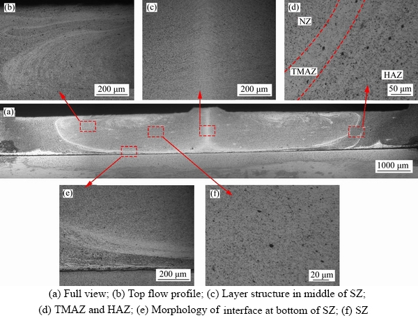
Figure 4 Macro- and micro-structures of pinless FSSW joint produced at rotational speed of 1180 r/min and dwell time of 15 s:
3.1.2 Analysis of microstructure of titanium side
Figure 6 shows the microstructure of the middle part of the Ti sheet under different parameters. It is suggested that the change of technological parameters has no obvious effect on the Ti sheet, the titanium side is still in the original state or slightly deformed (near the interface).
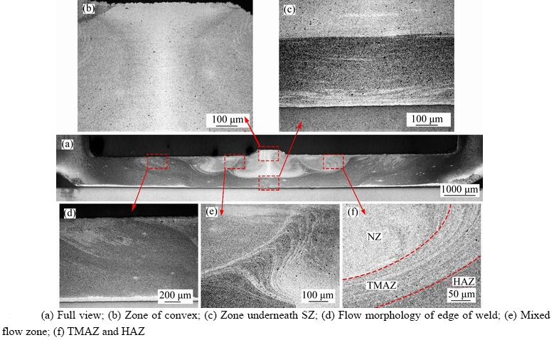
Figure 5 Macro- and micro-structure of pinless FSSW joint produced at rotational speed of 1500 r/min and dwell time of 15 s:

Figure 6 Schematic illustration of observation position and microstructure of titanium side:
3.2 Analysis of flow behavior of weld metal
As shown in Figure 4(a), a typical metal flow pattern of the joint microstructure can be found at lower rotational speed of 1180 r/min. Figure 7 shows the schematic diagram of metal flow pattern. From Figure 7, the metal of A zone at Al side firstly starts to soften and then flow during the process of welding. With the welding time increasing, A zone gradually expands to B zone and flows along the arrow direction, which is the same as the streamlines, shown in Figure 4(a). The main flow pattern in the central part C zone is between two symmetrical B zones. The part C zone is regional rotary and finally displays the convex morphology. The proportion of A, B and C zones changes with the influence of process parameters.
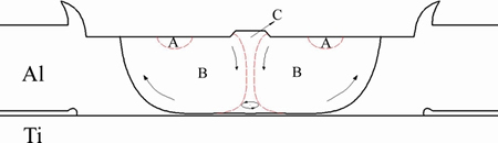
Figure 7 Schematic diagram of weld metal flow pattern
However, it is difficult to explain the material flow pattern in Figure 5(a) with the above flow model. In this case, as the rotational speed increases, the heat production increases. And the stirring action is enhanced. So the welding depth will increase and the heat will gradually spread to lower sheet. However, the difference of physical property between the aluminum alloy and titanium alloy is too large, no obvious softening of material occurs in titanium side and the material is difficult to flow. The metal should have flowed to the lower sheet, but are hindered by the unsoftened Ti alloy. The force of impact by the lower sheet on the flowing metal causes the wave flow as shown in Figure 5(e), which results in more complex flow patterns such as Figures 3(c) and (d).
3.3 Analysis of mechanical properties of joints
3.3.1 Effect of process parameters on mechanical properties of joints
Figure 8 shows photos of tensile specimens under different parameters. It can be seen from Figures 8(a) and (b) that all of the joints surfaces are of good quality. Figure 9 shows the load- displacement curves of pinless FSSWed joints under different process parameters. As shown in Figure 9, the load increases with the increase of displacement. When the load reaches the maximum value, all of the tensile specimens fracture immediately. It can be seen that the maximum load of the pinless FSSW joints is 1.79 kN when the rotation speed is 1500 r/min and the dwell time is 15 s.
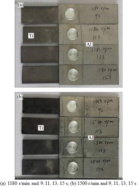
Figure 8 Photos of tensile specimens under different rotational speeds and dwell time:
Figure 10 shows the tensile curve and the maximum failure load of the pinless FSSW joint under different process parameters. From Figures 10(a) and (b), it can be seen that at the same rotation speed, the maximum load of joints increases with increasing dwell time. The reason is that the heat generated by the friction between the shoulder and the sheet is low when the dwell time is short. With the increase of dwell time, the friction heat increases, and it can be transmitted to the lower plate, which makes the metal fully softened and enhances the flow capacity of metal. So the joint strength increases with the increase of the depth and the width of the SZ. In addition, it also can be found that the higher the rotation speed is, the higher the maximum load is.
Figure 11 shows the microhardness distribution of cross section of pinless FSSW joint. The process parameters of the joint are as follows: rotational speed is 1500 r/min and dwell time is 15 s. As shown in Figure 11, the microhardness distribution of aluminum plate of joint shows a typical ��W�� type. The microhardness of the SZ is consistent with the base metal, and the minimum value of the hardness appears in the HAZ. In addition, there is no significant change in the microhardness of cross section of the titanium plate. The reason is that the difference of physical properties between aluminum alloy and titanium alloy is too large. Figure 11(c) shows the microhardness of the joint in the longitudinal direction. Because the heat input at the surface is the largest, and the softening effect is evident, the hardness value of aluminum side is lower at the beginning. The farther away from the surface, the smaller the thermal effect. The deformation hardening is caused by the metal flow and extrusion, so the microhardness increases. Subsequently, the decrease of the squeezing effect decreases the hardness value. Finally, the sharp rise in the value of hardness is due to the sharp increase in the effect of titanium plate on the upper plate. However, there is no significant change in the hardness values of the aluminum side.
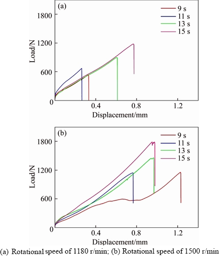
Figure 9 Load�Cdisplacement curves of pinless FSSWed joints under different process parameters:
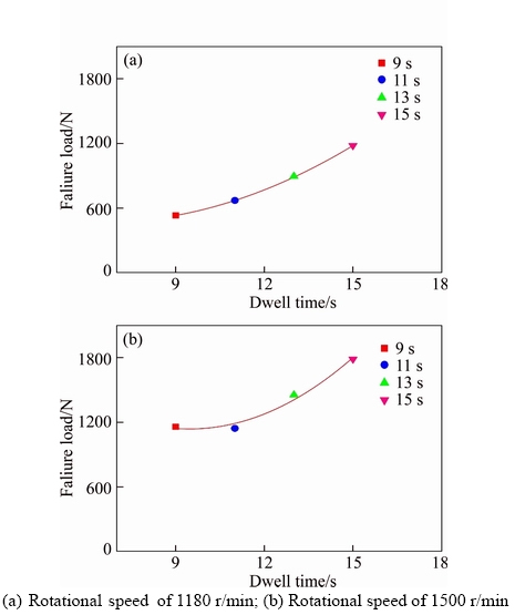
Figure 10 Maximum load of pinless FSSWed joints under different process parameters:
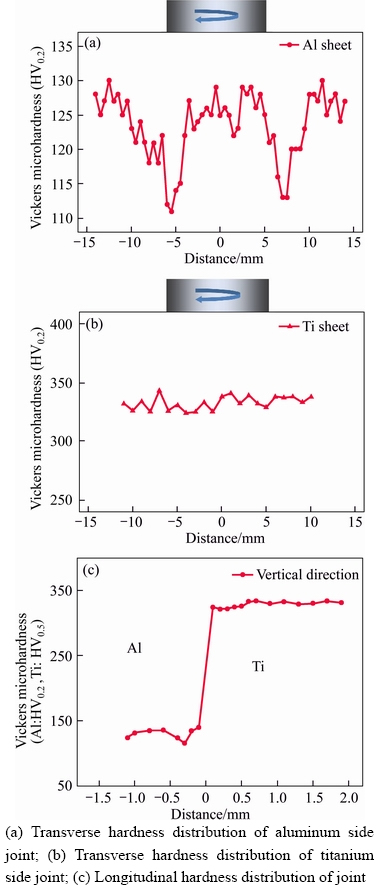
Figure 11 Microhardness distribution of joint produced at rotational speed of 1500 r/min and dwell time of 15 s:
3.3.2 Fracture morphology analysis
Figure 12 shows the SEM photographs of the fracture surface of the two typical aluminum sides. Figure 12(a) shows a fracture surface of aluminum side of typical weak joint. Figure 12(b) shows another fractograph of the joint which corresponds to the maximum failure load. Comparing between Figures 12(c) and (e), there is no ductile shear. There are some pits or heaves caused by the drop of parts of the metal in Figure 12(e), but there are evident lamellar dilacerations tracks in Figure 12(c) which have a certain flow line. It shows that the connected region is focused on the white circle site in the middle of the welding part. However, only a small part outside the circle combines with the titanium sheet in welding which means the great metallurgical structures do not develop, which can also be confirmed by Figures 12(d) and (f). The comparison of the dimple in the certain part of Figure 12(d) and the lamellar dilacerations shows that the great structure is formed. The zone shown in Figure 12(f) is similar with that in Figure 12(e), but the drop of the metal is more concentrated.
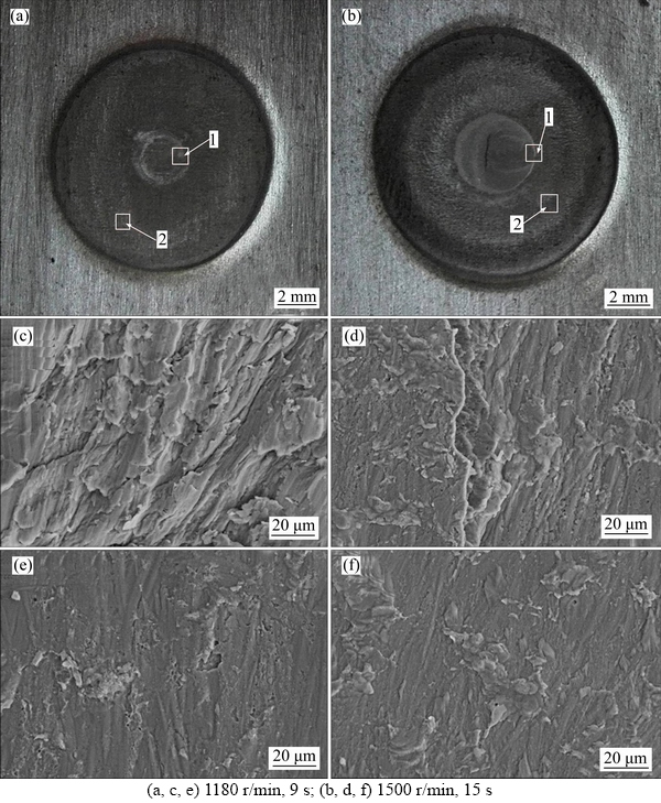
Figure 12 Fractographs of Al side of two different failure samples:
4 Conclusions
Al/Ti dissimilar alloys are successfully welded through pinless FSSW in this work. Then the microstructure and mechanical properties of joint are analyzed. The conclusions are drawn as follows:
1) The welded joint shows three regions: SZ, TMAZ and HAZ, and they mainly present on the Al side. The microstructure of the Ti side has almost no change.
2) The weld metal begins to soften from the area between the center and the edge of the weld, and to flow from the surface to the bottom, from the center near the weld to the edge of the weld. This zone is gradually expanded to the entire joint, forming the morphology of the two semicircular shapes along the weld center symmetry.
3) At the same rotation speed, the maximum load of the welded joints increases gradually with increasing dwell time. The optimal parameters are: rotational speed of 1500 r/min, plunging speed of 30 mm/min, shoulder plunge depth of 0.3 mm, dwell time of 15 s, and maximum load of 1.79 kN.
4) The bonded region is located at the central region of the interface, and all the fractures present a shear fracture mode. The hardness tests show that the microhardness of the joint on the Al side distributes in a typical ��W�� type and is symmetry along the weld center, but the microhardness distribution on the Ti side has no evident change.
References
[1] SHEN J, LI Y, ZHANG T, PENG D, WANG D, XU D. Preheating friction stir spot welding of Mg/Al alloys in various lap configurations [J]. Science and Technology of Welding and Joining, 2015, 20(1): 1�C10.
[2] LIU J, GOU WX, LIU W, YUE Z F. Effect of hammer peening on fatigue life of aluminum alloy 2A12-T4 [J]. Materials and Design, 2009, 30: 1944�C1949.
[3] NIE Bao-hua, ZHANG Zheng, ZHAO Zi-hua, ZHONG Qun-peng. Effect of anodizing treatment on the very high cycle fatigue behavior of 2A12-T4 aluminum alloy [J]. Materials and Design, 2013, 50: 1005�C1010.
[4] XU Wei-feng, ZHANG Zhen-lin. Microstructure and mechanical properties of laser beam welded TC4/TA15 dissimilar joints [J]. Transactions of Nonferrous Metals Society of China, 2016, 26(12): 3135�C3146.
[5] JI Shu-de, LI Zheng-wei, Wang YUE, MA Lin. Joint formation and mechanical properties of back heating assisted friction stir welded Ti-6Al-4V alloy [J]. Materials and Design, 2017, 113: 37�C46.
[6] YAN Hong, ZHANG Ji-xiong, LI Lin-yue, FENG Rui-min, LI Tian-tong. Prediction of upper limit position of bedding separation overlying a coal roadway within an extra-thick coal seam [J]. Journal of Central South University, 2018, 25(2): 448�C460.
[7] JI Shu-de, LI Zheng-wei, ZHANG Li-guo, WANG Yue. Eliminating the tearing defect in Ti-6Al-4V alloy joint by back heating assisted friction stir welding [J]. Materials Letters, 2017, 188: 21�C24.
[8] SQUIRES L, LIM Y C, MILES M P, FENG Z. Mechanical properties of dissimilar metal joints composed of DP 980 steel and AA 7075-T6 [J]. Science and Technology of Welding and Joining, 2015, 20(3): 242�C248.
[9] WU Sai-nan, GHAFFARI B, HETRICK E, LI Mei, JIA Zhi-hong, LIU Qing. Microstructure characterization and quasi-static failure behavior of resistance spot welds of AA6111-T4 aluminum alloy [J]. Transactions of Nonferrous Metals Society of China, 2014, 24(12): 3879�C3885.
[10] TAO Jian-feng, GONG Liang, LIU Cheng-liang, ZHAO Yang. Multi-field dynamic modeling and numerical simulation of aluminum alloy resistance spot welding [J]. Transactions of Nonferrous Metals Society of China, 2012, 22(12): 3066�C3072.
[11] VENUKUMAR S, YALAGI S G, MUTHUKUMARAN S, KAILAS S V. Static shear strength and fatigue life of refill friction stir spot welded AA 6061-T6 sheets [J]. Science and Technology of Welding and Joining, 2014, 19(3): 214�C223.
[12] ZHANG H, WANG D, XUE P, WU L H, NI D R, MA Z Y. Microstructural evolution and pitting corrosion behavior of friction stir welded joint of high nitrogen stainless steel [J]. Materials & Design, 2016, 110: 802�C810.
[13] KAMRAN A, FARHAD G. Influence of welding speed on corrosion behaviour of friction stir welded AA5086 aluminium alloy [J]. Journal of Central South University, 2016, 23(6): 1301�C1311.
[14] WU L H , XUE P, XIAO B L, MA Z Y. Achieving superior low-temperature superplasticity for lamellar microstructure in nugget of a friction stir welded Ti-6Al-4V joint [J]. Scripta Materialia, 2016, 122: 26�C30.
[15] LIU Hui-jie, HU Yan-ying, DOU Chao, SEKULIC D P. An effect of the rotation speed on microstructure and mechanical properties of the friction stir welded 2060-T8 Al-Li alloy [J]. Materials Characterization, 2017, 123: 9�C19.
[16] LIU Hui-jie, HU Yan-ying, ZHAO Yun-qiang. Microstructural characteristics and formation mechanism of friction stir welds of SiC particulates reinforced Al�CSi matrix composites [J]. Materials Letters, 2015, 158: 136�C139.
[17] SUTTON M A, REYNOLDS A P, YANG Bang-cheng, Taylor R. Mode I fracture and microstructure for 2024-T3 friction stir welds [J]. Materials Science and Engineering A, 2003, 354(1, 2): 6�C16.
[18] BAKAVOS D, PRANGNELL P B. Effect of reduced or zero pin length and anvil insulation on friction stir spot welding thin gauge 6111 automotive sheet [J]. Science and Technology of Welding and Joining, 2009, 14(5): 443�C456.
[19] LI Wen-ya, CHU Qiang, YANG Xia-wei. Microstructure and morphology evolution of probeless friction stir spot welded joints of aluminum alloy [J]. Journal of Materials Processing Technology, 2017, 252: 69�C80.
[20] YANG Xia-wei, FENG Wu-yuan, LI Wen-ya, XU Ya-xin, CHU Qiang, MA Tie-jun, WANG Wei-bing. Numerical modelling and experimental investigation of thermal and material flow in probeless friction stir spot welding process of Al 2198-T8 [J]. Science and Technology of Welding and Joining, 2018, DOI: 10.1080/13621718.2018.1469832.
(Edited by FANG Jing-hua)
���ĵ���
2A12���Ͻ���TC4�ѺϽ��������Ħ���㺸��֯������
ժҪ���������2A12���Ͻ���TC4�ѺϽ𣬲����������Ħ���㺸�����о��˲�ͬ���ղ����µ����ʽ�ͷ����֯�����ܡ��о����������ͨ���������Ħ�������Գɹ����Al/Ti���ʺϽ��ͷ�����ҽ�ͷ�ɷ�Ϊ�������͵���������������Ӱ��������Ӱ������Al���ͷ������֯�仯�Ƚ���������Ti����֯û�����Եı仯����������Ľ������������ͬ�Ľ���ͷ��ת�ٶ��£���ͷ����������غ���ͣ��ʱ��������������ͬһͣ��ʱ���£�ת��Խ���ͷ����������غ�ҲԽ���⣬��ת��1500 r/min��ͣ��ʱ��15 sʱ��ͷ��ǿ����ߣ���ͷ�Ķ���ģʽΪ������ж��ѡ���Ӳ�Ȳ��Խ����ʾ����ͷAl���Ӳ��ֵ�ʵ��͵ġ�W���ֲ����ؽ�ͷ�����߶Գƣ���Ti���Ӳ��ֵû�����Եı仯��
�ؼ��ʣ�����֯����ѧ���ܣ�����Ħ���㺸�����ʽ�ͷ
Foundation item: Projects(51405389, 51675435) supported by the National Natural Science Foundation of China; Project(3102017ZY005) supported by the Fundamental Research Funds for the Central Universities, China; Project(SAST2016043) supported by the Fund of SAST, China; Project(20161125002) supported by the Aeronautical Science Foundation of China; Project(B08040) supported by the 111 Project, China; Projects(2016YFB0701203, 2016YFB1100104) supported by the National Key Research and Development Program of China
Received date: 2017-05-29; Accepted date: 2018-02-14
Corresponding author: LI Wen-ya, PhD, Professor; Tel: +86-29-88495226; E-mail: liwy@nwpu.edu.cn
Abstract: The microstructure and mechanical properties of dissimilar pinless friction stir spot welded joint of 2A12 aluminum alloy and TC4 titanium alloy were evaluated. The results show that the joint of Al/Ti dissimilar alloys can be successfully attained through pinless friction stir spot welding (FSSW). The joint can be divided into three zones (SZ, TMAZ and HAZ). The microstructure of joint in Al alloy side changes significantly but it basically has no change in Ti alloy side. At the same rotation speed, the maximum load of welded joints gradually rises with the increase in dwell time. At the same dwell time, the maximum load of the welded joint increases with the increase of the rotational speed. In addition, optimal parameters were obtained in this work, and they are rotation speed of 1500 r/min, plunge speed of 30 mm/min, plunge depth of 0.3 mm and dwell time of 15 s. The fracture mode of welded joints is interfacial shear fracture. The microhardness of the joint on the Al side distributes in a typical ��W�� type and is symmetry along the weld center, but the distribution of the microhardness on the Ti side has no obvious change.
