
�ȳ�����װ����ͬ������ϵͳ�����
�ƽ, ������, ������, �� ��, �� ��
(���ϴ�ѧ ���繤��ѧԺ, ���� ��ɳ, 410083)
ժ Ҫ��
װ���ϲ���ϵͳͬ������ʵ��Ա��о��˵�Ƭ��ɨ�蹤��ģʽ�͵�Ƭ���жϹ���ģʽ����ϵͳ���ȶ��Ժʹ����ӳٷ�������ܡ� ʵ��������: ��Ƭ���жϹ���ģʽ�Ĵ���ϵͳ���и��ȶ�������ӳ�ʱ�䡢 ƽ���ӳ�ʱ����ӳ�ʱ�������, ����ӳ�ʱ�䡢 ƽ���ӳ�ʱ����ӳ�ʱ�������ȵ�Ƭ��ɨ�蹤��ģʽ�Ĵ���ϵͳ�ĵ�, �ر������ӳ�ʱ��������Ϊ0.5 ��s�� ��Ƭ���жϹ���ģʽ�Ĵ���ϵͳ��ƽ�������ӳ�ʱ��Ϊ9 ��s, С���ȳ�����������ÿ�δ����ӳ�ʱ��㶨�� ���ȳ�����װ�������ݲɼ�ϵͳ�Ͷ����ղ���ϵͳ����ͬ������ʵ��, �����һ��֤ʵ: �жϹ���ģʽ�Ĵ���ϵͳ�ܹ������ȳ�����װ�������ݲɼ�ϵͳ�Ͷ����ղ���ϵͳ��ʵʱ�ԡ� ��ȷ�Լ��ȶ��Եȷ����Ҫ��, ����ʵ�ֶ���Ч���ݵľ�ȷ��ȡ��
�ؼ���: �ȳ���; ��װ����; ����; �ж�; ɨ��
��ͼ�����:TN345+.4 ���ױ�ʶ��:A ���±��: 1672-7207(2005)06-1026-05
Synchronization trigger system design of thermosonic flip-chip bonding
LI Jian-ping, HUO Jun-ya, WANG Fu-liang, HAN Lei, ZHONG Jue
(School of Mechanical and Electrical Engineering, Central South University, Changsha 410083, China)
Abstract: The stability and the delay time of the scan working model trigger system and the interrupt working model trigger system were compared and studied by the experiment of synchronization trigger of the thermosonic flip-chip bonding. It is found that the stability of the interrupt working model trigger system is better than that of the scan working model trigger system. The biggest value, average value and the standard deviation of the delay time are all smaller than those of the scan working model trigger system, especially the standard deviation is just as small as 0.5��s. The result indicates that the delay time of the interrupt working model trigger system is 9 ��s, which is less than a cycle of the thermosonic and invariableness. The interrupt working model trigger system is superior to that of the scan working model trigger system. It is also confirmed that it can be used as a precise synchronization trigger system by triggering the thermosonic flip-chip bonding��s data acquisition system and polytec vibration measure system.
Key words: thermosonic; flip-chip bonding; triggering; interruption; scan
�ȳ�����������Ŀǰ��ͨ�õ�оƬ��������[1-3], �ڼ��Ϲ����м����ȳ���, ��������ʵ�ֵ��º��ӴӶ�ʹ���ձ�ü�[4,5], ���ҿ���ʵ�ִ�ͳ���Ӽ�����ʵ�ֵIJ�ͬ�۵���������֮��ļ���[6,7], ���, ��оƬ���������еõ��㷺��Ӧ��[8-10]�� ����, �ȳ��������ϴ��ڳɱ��ߡ� Ч�ʵ͡� ֻ��ʵ�ֵ�����ϵ�ȱ��[11]�� ���ȳ�����װоƬ��������гɱ��͡� �����á� ���С�� Ч�ʸ�[12-14], һ�ο���ʵ�ֶ����ϵ��ŵ�[15-17], ��Ҳ���ڹ��ո��ӡ� ���Կ��Ƶ�ȱ��[18,19]�� �ȳ�����װ��������һ���ۺ��˶����ŵ㡢 �˷�����ȱ���оƬ���Ӽ���, Ŀǰ������������ʵ��Ρ� ��ʵ�������, ͨ�����ȳ���������ϵͳ���ȳ�����װϵͳ��Ҫ������ѹ�� �����������ȳ����ȹؼ����������IJɼ�, �����ȳ��������ϻ������ȳ�����װ����, ��ʾϵͳ�����������ȳ���������ϵͳ���ȳ�����װϵͳ��Ӱ��, Ȼ���ȳ���������ϵͳ���ȳ�����װϵͳ��װΪ�ȳ�����װ����ʵ��װ��, �����ݼ���Ч��������Եĸı�ϵͳ����, ����ϵͳ����[20], ����ȳ�����װ���������� ��Ϊ�ȳ�����װ���ϻ�������ʮ�ָ���, ��ʵ��������ȳ���������ϵͳ���ȳ�����װϵͳ�������ĵ�ѹ�͵����������ȳ�������ͬ������, ��Ҫһ������ϵͳ��������ͬʱ����, Ҫ��ϵͳ���ӳ�ʱ��С���ȳ�����1��ʱ������, ÿ���ӳ�ʱ��㶨�� Ŀǰ, ���еĴ���ϵͳ���������ȳ�����װ����ͬ������ʵ���Ҫ�� �ڴ�, ���߽�����ݲɼ�ϵͳ�Ͷ����ղ���ϵͳ���һ���ȶ����ⲿ����ϵͳ, �Խ���ȳ�����װ����ʱ��ѹ�� �������ݲɼ��������ȳ���������ͬ������������, ʵ�ֶ���Ч���ݵ�ȷ��ȡ��
1 �ȳ�����װ����װ��
�ȳ�����װ����ʾ��ͼ��ͼ1��ʾ, ��Ҫ�����ȳ�������װ�á� PZT�������� �г����� ����ˡ� ������ ����̨�ȡ� ����ԭ��Ϊ: �ȳ�����������������Ƶ�ʵĵ��źž�PZT������ת��Ϊ��е��, ��������˺���������Ŵ��������оƬ��, ��ѹ�����ȳ����������½�оƬ�ϵĶ��������ͻ��庸��1�ε�װ������һ��
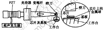
ͼ 1 �ȳ�����װ����װ��ϵͳʾ��ͼ
Fig. 1 Sketch of thermosonic flip-chip bonding system
����ϵͳ�������ź���ϵͳ�ȳ�����װ����ʱ�ȳ�����������������ѹ, ������ѹ����������ͼ2��ʾ, ������ѹ���ֲ�����ͼ3��ʾ, Ƶ��Ϊ60 kHz�� ����ϵͳ���ߵ�ƽ�ź�����ʱ�����ߵ�ƽ�ź����������ݲɼ�ϵͳ�Ͷ����ղ�����ͬ��������
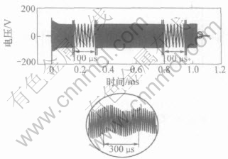
ͼ 2 �ȳ�����װ����װ��ϵͳ������ѹ��������
Fig. 2 Full waveform of driving voltage of thermosonic flip-chip bonding system
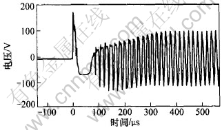
ͼ 3 �ȳ�����װ����װ��ϵͳ������ѹ���ֲ���
Fig. 3 Part waveform of driving voltage of thermosonic flip-chip bonding system
2 ����ϵͳ���
2.1 ����ɨ�蹤��ģʽ�Ĵ���ϵͳ��ԭ����ʵ��
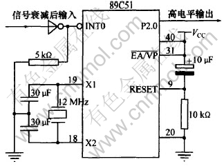
���ݵ�Ƭ����ɨ�蹤��ԭ�����Ӳ������ϵͳ, ��ʵ�ִ�������[21]�� ���·ԭ����Ʋ�����ͼ4��ʾ, ��������ͼ��ͼ5��ʾ�� ��89C51��Ƭ����Ϊ����ϵͳ�Ŀ�������, ��Ƭ����P1.0�˿�Ϊ����ϵͳ������˿�, P2.0Ϊ����ϵͳ������˿�; �����ⲿʱ�ӵ�·, ����Ƶ��Ϊ12 MHz; �˿�31��9�����ӵ�·Ϊ��λ������·; ����˿ڽ�5 k���ĵ�����Ϊ�˷�ֹ�������̫��Ե�Ƭ�������, ���øߵ�ƽ������
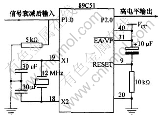
ͼ 4 ɨ�蹤��ģʽ����ϵͳ�ĵ�·ԭ��ͼ
Fig. 4 Circuit principium diagram of scan working model trigger system
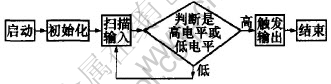
ͼ 5 ɨ�蹤��ģʽ�Ĵ���ϵͳ��������ͼ
Fig. 5 Software flow chart of scan working model trigger system
ϵͳ������Ƭ����ʼ����ɨ������˿�, ֱ��ɨ�赽����˿�Ϊ�ߵ�ƽ�ź�ʱ����ɨ��, ��P2.0�˿�����ߵ�ƽ�źŴ������ݲɼ�ϵͳ�Ͷ����ղ���ϵͳͬ��������
2.2 �����жϹ���ģʽ�Ĵ���ϵͳԭ����ʵ��
���ݵ�Ƭ�����жϹ���ԭ�����Ӳ������ϵͳ, ��ʵ�ִ�������[22]�� ��·ԭ�������ͼ6��ʾ, ��ɨ�蹤��ģʽ����ϵͳԭ��ͼ�IJ�֮ͬ�����ڸô���ϵͳ���ⲿ�ж϶˿�INT0����P1.0��Ϊ����ϵͳ����˿�, ���ڵ�Ƭ���ⲿ�ж˿ڹ���ģʽֻ�����½��ػ��ߵ͵�ƽ��Ч, ��������ѹ�ź���ʼΪ�����ź�, ����, �ź����뵥Ƭ��֮ǰ�Ⱦ���һ������ת��, �趨��Ƭ���жϹ���ģʽΪ�½��ش�����
����ϵͳ��������������ͼ7��ʾ��
ϵͳ������, ��Ƭ����ʼ�������еȴ��ж�, �ȵ�����ϵͳ����˿������ص���ʱ, ��Ƭ���ж϶˿ڻ����һ���½���, ��Ƭ�������½��ؾ�����ߵ�ƽ�ź�, ���źŴ����ȳ�����װ�������ݲɼ�ϵͳ�Ͷ����ղ���ϵͳͬ��������
ͼ 6 �жϹ���ģʽ�Ĵ���ϵͳ��·ԭͼ
Fig. 6 Circuit principium diagram of interrupt working model trigger system
![]()
ͼ 7 �����жϹ���ģʽ����ϵͳ����������ͼ
Fig. 7 Software flow chart of interrupt working model trigger system
3 ����ͷ���
ʵ�ʲ���2������ϵͳ�ӳ�ʱ�����ݸ�1000����Ϊ�������, ɨ�蹤��ģʽ����ϵͳ�Ĵ����ӳ�ʱ��ֲ���ͼ8��ʾ, �жϹ���ģʽ����ϵͳ�Ĵ����ӳ�ʱ��ֲ���ͼ9��ʾ�� ����, �����ʾ�ӳ�ʱ��, �����ʾ�����ӳ�ʱ������Ӧ��ʱ��γ��ֵĴ���, ɨ�蹤��ģʽ�����ӳ�ʱ��ֲ���8~19 ��s֮��, ����ӳ�ʱ��Ϊ19 ��s, ƽ��ʱ��Ϊ13 ��s, �ӳ�ʱ�������Ϊ3 ��s�� ������ϴ�, ����������ӳٲ����ϴ�, ������Ϊ��Ƭ��������ѭ
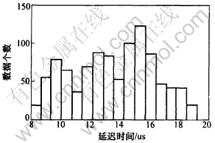
ͼ 8 ɨ�蹤��ģʽ�Ĵ����ӳ�ʱ��ֲ�ֱ��ͼ
Fig. 8 Delay time distribution straight square chart of scan working model trigger system
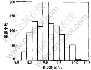
ͼ 9 �жϹ���ģʽ�Ĵ����ӳ�ʱ��ֲ�ֱ��ͼ
Fig. 9 Delay time distribution straight square chart of interrupt working model trigger system
��ɨ��Ĺ�����ʽ, ����ѭ����Ϊ:
LOOP: MOV C, P1.0
RLC A
CJNE A, #1, AA ; �ɼ�P1.0�˿������� 1�Ƚϴ�С
AA: JNC OUT ; ���ڻ����1��ת��OUT, ��������ִ��
AJMP LOOP ; ��ת��LOOP
�ڴ�ѭ������, ֻ��һ��MOV C,P1.0�Dzɼ�P1.0�˿ڵ�ѹ�ź�, ֻ�е���ѹ�ź�Ϊ�ߵ�ƽ�������е�MOV C,P1.0ϵͳʱ, ��ͨ���Ƚ�����ߵ�ƽ�����źš� ���, �Ӵ���ϵͳ����˿ڳ��ָߵ�ƽ�źŵ�����ϵͳ����ߵ�ƽ�����źŵ��ӳ�ʱ�䲻��ȷ�� ���жϹ���ģʽ�Ĵ���ϵͳ����Ҫѭ��ִ�г���, ����, �ӳ�ʱ��϶�, ���Ҵ���ϵͳÿ�δ���ǰ��ִ�еȴ��жϵ�����, ÿ�δ����ӳ�ʱ���ǹ̶��ġ� �жϹ���ģʽ��ɨ�蹤��ģʽ�Ĵ���ϵͳ�ӳ�ʱ�似�������Ա����1��ʾ��
�� 1 ɨ�蹤��ģʽ�Ĵ���ϵͳ���жϹ���ģʽ�Ĵ���ϵͳ�ӳٲ���
Table 1 Delay parameters of scan working model trigger system and interrupt working
model trigger system
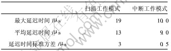
�ɼ�, �жϹ���ģʽ�Ĵ���ϵͳ���ӳٱ�����Ϊ0.5 ��s, ԶС��ɨ�蹤��ģʽ�Ĵ���ϵͳ���ӳٱ�����(3 ��s), ˵���жϹ���ģʽ�Ĵ���ϵͳ�ӳ�ʱ��㶨, ԶԶ����ɨ�蹤��ģʽ�Ĵ���ϵͳ�� �����жϹ���ģʽ�Ĵ���ϵͳ�ɹ��������ݲɼ�ϵͳ�ɼ�������ѹ��ͼ2��ʾ, ����������ͼ10��ʾ�� ͬ�����������ղ���ϵͳ�ɲ���������ȳ�����
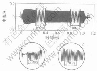
ͼ 10 �ȳ�����װ����װ��ϵͳ
����������������
Fig. 10 Full waveform of driving current of thermosonic flip-chip bonding system
4 �� ��
ͨ��ʵ��֤ʵ���жϹ���ģʽ�Ĵ���ϵͳ�����ȶ�, ƽ�������ӳ�Ϊ9 ��s, �ӳ�ʱ��������Ϊ0.5 ��s, ������1���ȳ���������ʵ�ֶ��ȳ�����װ�������ݲɼ�ϵͳ�Ͷ����ղ���ϵͳ�ľ�ȷ����, �Ӷ�ʵ�������ݲɼ�ϵͳ�Ͷ����ղ����ǵ�ͬ������, ���ȳ�����װ����ʵ���и�������ѹ�� �����������ȳ�������Ч���ݽ��о�ȷ��ȡ, Ϊ�ȳ�����װ����ϵͳ�Ļ���������ϵͳ�Ľ��ṩ�˲���������
�����:
[1]Johnson R W , Palmer M J, Bozack M J, et al. Thermosonic gold wire bonding to laminate substrates with palladium surface finishes[A]. IEEE Transactions on Electronics Packaging Manufacturing[C]. Denver: Institute of Electrical and Electronics Engineers, 1999, 22(1) : 7-15.
[2]Jeng Y R , Chen J Y. On the microcontact mechanism of thermosonic wire bonding in microelectronics: Saturation of interfacial phenomena[J]. Tribology Transactions, 2005, 48(1): 127-132.
[3]Wei T C, Daud A R. Cratering on thermosonic copper wire ball bonding[J]. Journal of Materials Engineering and Performance, 2002,11(3): 283-287.
[4]Faridi H R, Devletian J H, Le H P. A new look at flux-free ultrasonic soldering[J]. Welding Journal, 2000, 79(9): 41-45.
[5]Koepfer C. Ultrasonic technology helps machine hard materials[J]. Modern Machine Shop, 2002, 74(12): 60-61.
[6]Jeng Y R, Aoh J H, Wang C M. Thermosonic wire bonding of gold wire onto copper pad using the saturated interracial phenomena[J]. Journal of Physics D: Applied Physics, 2001,34(24): 3515-3521.
[7]Aoh J N,Chuang C L. Thermosonic bonding of gold wire onto a copper pad with titanium thin-film deposition[J]. Journal of Electronic Materials, 2004, 33(4): 290-299.
[8]Smith R W, Stradling J, Butera M. Ultrasonic solder joint inspection and analysis [J]. Welding Journal, 2003,82(10): 80-82.
[9]Ulrich R, Wasef M, Im J, et al. Thermosonic gold wire bonding to electrolessly-metallized copper bondpads over benzocyclobutene[A] Proceedings of SPIE - The International Society for Optical Engineering [C]. Denver: The International Society for Optical Engineering, 1999. 260-265.
[10]Aoh J C, Chuang C L. Development of a thermosonic wire-bonding process for gold wire bonding to copper pads using argon shielding[J]. Journal of Electronic Materials, 2004, 33(4) : 300-311.
[11]Bursky D. Enhanced flip-chip packaging technique boosts IC reliability and performance[J]. Electronic Design,1999,47(17): 29-30.
[12]Tomioka T, Iguchi T, Mori I, et al. Thermosonic flip chip bonding for low cost packaging[A]. Proceedings of SPIE-The International Society for Optical Engineering [C]. Denver: The International Society for Optical Engineering, 2002. 360-365.
[13]Pang C C H , Hung K Y, Sham M L. High frequency thermosonic flip chip bonding for gold to gold interconnection[A]. Proceedings-54th Electronic Components and Technology Conference[C]. Piscataway: Institute of Electrical and Electronics Engineers, 2004. 1461-1465.
[14]Pascariu G, Cronin P, Crowley D. Next-generation electronics packaging using flip chip technology[J]. Advanced Packaging, 2003, 12(11): 21-26.
[15]Cheah L K, Tan Y M, Wei J, et al. Gold to gold thermosonic flip-chip bonding[A]. Proceedings of SPIE - The International Society for Optical Engineering[C]. Santa Clara: Society of Photo-Optical Instrumentation Engineers, 2001. 165-170.
[16]Wei J, Wang Z P, Tan Y M. Gold to gold thermosonic flip chip bonding on ceramic substrate[A]. American Society of Mechanical Engineers,EEP[C]. New Orleans: American Society of Mechanical Engineers 2002: 431-436.
[17]Tomioka T, Iguchi T, Mori I. Thermosonic flip-chip bonding for SAW filter[J]. Microelectronics Reliability, 2004, 44(1): 149-154.
[18]Tan Q, Zhang W, Schaible B, et al. Thermosonic flip-chip bonding using longitudinal ultrasonic vibration[A]. Proceedings 47th Electronic Components and Technology Conference[C]. New York: Institute of Electrical and Electronics Engineers, 1997. 1128-1133..
[19]Kang S Y, Mclaren T, Wenge Z, et al. Thermosonic bonding for flip-chip assembly[A]. Proceedings of 1995 IEEE Multi-Chip Module Conference[C]. Los Alamitos: IEEE Comput Soc Press, 1995. 75-80.
[20]Fred R. Schraff P E. Data acquisition system gets the facts on glass production testing [J]. Control Solut, 2003, 76(3): 15-16.
[21]Thomas S S. The trigger of the ATLAS Experiment[J]. Modern Physics Letters, 2003,18(31): 2149-2168.
[22]Bloom K. Fast track triggering for the CDF �� detector[A]. International Journal of Modern Physics A[C]. Singapore: World Scientific,2001,16(1): 1172-1174.
�ո�����:2005-05-06
������Ŀ: �����ش���Ȼ��ѧ����������Ŀ(50390064); ���ҽ�������ѧ�ع���Ա����������Ŀ(76084); ���ҡ�973���ƻ���Ŀ(2003CB716202)
�����: �ƽ(1952-), ��, ���ϳ�ɳ��, ����, ��ʿ, �������ӷ�װ�о�
������ϵ��: �ƽ, ��, ����, ��ʿ; �绰: 0731-8830293(O); E-mail: rikennpei102@hotmail.com
ժҪ: ͨ���ȳ�����װ���ϲ���ϵͳͬ������ʵ��Ա��о��˵�Ƭ��ɨ�蹤��ģʽ�͵�Ƭ���жϹ���ģʽ����ϵͳ���ȶ��Ժʹ����ӳٷ�������ܡ� ʵ��������: ��Ƭ���жϹ���ģʽ�Ĵ���ϵͳ���и��ȶ�������ӳ�ʱ�䡢 ƽ���ӳ�ʱ����ӳ�ʱ�������, ����ӳ�ʱ�䡢 ƽ���ӳ�ʱ����ӳ�ʱ�������ȵ�Ƭ��ɨ�蹤��ģʽ�Ĵ���ϵͳ�ĵ�, �ر������ӳ�ʱ��������Ϊ0.5 ��s�� ��Ƭ���жϹ���ģʽ�Ĵ���ϵͳ��ƽ�������ӳ�ʱ��Ϊ9 ��s, С���ȳ�����������ÿ�δ����ӳ�ʱ��㶨�� ���ȳ�����װ�������ݲɼ�ϵͳ�Ͷ����ղ���ϵͳ����ͬ������ʵ��, �����һ��֤ʵ: �жϹ���ģʽ�Ĵ���ϵͳ�ܹ������ȳ�����װ�������ݲɼ�ϵͳ�Ͷ����ղ���ϵͳ��ʵʱ�ԡ� ��ȷ�Լ��ȶ��Եȷ����Ҫ��, ����ʵ�ֶ���Ч���ݵľ�ȷ��ȡ��
