
���±�ţ�1004-0609(2007)10-1622-05
12 mm���ѺϽ�ƽ����������ӵ���ֵģ��
�����꣬�����
(������ҵ��ѧ ���Ͽ�ѧ�빤��ѧԺ������ 710072)
ժ Ҫ��
����ANSYS����Ԫ��������������12 mm��TC4�ѺϽ�ƽ������������¶ȳ���Ӧ��������ά����Ԫ��ֵ����ģ�͡�ģ�Ͳ���Բ����Դ���ǵ���������ʱ��С��ЧӦ�����ϵ���ѧ����ѧ���ܲ������¶ȱ仯�������۳���Һ��Ķ���ɢ��ͨ�����Ⱥ��ȵ��ʵı仯ʵ�֡��������������ѺϽ����������ʱ���۳سʵ��͵����ηֲ�����ֵ���������Ӧ�����зֲ��ں�������������ຸ��������4 mm�������ڣ�ƽ���ڲ����ֽӽ������������ľֲ���ά������Ӧ��״̬��ʵ��õ��ĺ�������ò��С���ͷŷ����ĺ��Ӳ���Ӧ���Լ�����������֤, ʵ�����ͼ������ǺϽϺã�֤��������Ԫģ�͵���ȷ�ԡ�
�ؼ��ʣ�
�ѺϽ�����������������ֵģ����С��������Ӧ����
��ͼ����ţ�TG 456.3���� ���ױ�ʶ�룺A
Numerical simulation for electron beam welding
of 12 mm-thickness titanium alloy plate
HU Mei-juan, LIU Jin-he
(School of Materials Science and Engineering, Northwestern Polytechnical University, Xi��an 710072, China)
Abstract: A three dimensional finite element model used for calculating electron beam welding temperature and stress fields of 12 mm-thickness TC4 titanium alloy plate was developed through employing ANSYS software code. Cone body heat source model was chosen to simulate keyhole effect of electron beam welding. Temperature-dependent thermal and mechanical properties were used. Phase change and liquid convection in molten bath were simulated by the change of specific heat and heat conductivity. The results of the simulation show that the shape of the weld pool is typically oval. The longitudinal stresses with high value mainly lie in the region which extends a distance 4 mm away from the weld centerline. The phenomenon of local three dimensions residual tensile stresses, which are equivalent to the yield stress of the material, appears in the plate center. Macrograph of the fusion zone in the transverse section obtained from experiment and residual stresses determined by hole-drilling method are used to validate the simulated results. The experimental and numerical results are in sufficient overall agreement, which proves the validity of the finite element model.
Key words: titanium alloy; electron beam welding; numerical simulation; hole-drilling method; residual stress
�ѺϽ����ھ��б�ǿ�ȸߡ������¶ȷ�Χ�����������Ժ��¿�����������õ��ŵ㣬�ں��պ��������ر��Ǻ��շ����������еõ��˹㷺��Ӧ�á�������յ��������Ӿ��������ܶȸߡ��������Ӱ����խ�����ӱ���С�����ղ�������ȷ���Ƽ���պ��ӻ������������ӷ������Ա�������ƣ�������Ϊ�ѺϽӷ�������ѡ[1-5]��
����������ʱ�����õĹ����ܶ��㹻��ʱ���γɴ��͵�����ëϸ�ס����ܵ��������Ӻ���������С�����Ǻ��Ӳ���Ӧ�������¶��ݶȴ���ܴﵽ�൱�ߵ���ֵ�����Ӳ���Ӧ����Ӱ��ṹ���Զ���ǿ�ȡ�ƣ��ǿ���Լ��ߴ��ȶ��Ե���Ҫ����[6-7]����������Ӧ������ά��ⳣ�ܵ����ޣ����÷��ƻ��Լ��ʱͨ��ֻ��ȷ�����������Ӧ��״̬����ʹ�����ƻ��Է���Ҳ���������㹻�ľ���ȷ�������ڲ���������άӦ��״̬[8]����ֵģ�⼼���ķ�չΪ�о������ȹ��̡�����Ӧ���Ķ�̬�仯�Լ����Ӳ���Ӧ���ķֲ��ṩ��һ����Ч�ķ�����
Stone��[9]����SYSWELD����Ԫ������������9 mm���������ǿ�Ͻ�ƽ����������ӹ��̽�������άģ����㣬��Դ����ͨ��ʵ������ģ�����ĶԱȻ�ã��������Ӧ����ģ����ͬʵ���������õ�һ���ԣ��������Ӧ���IJ��ϴ�ģ����ָ���������Ӧ������ΪѹӦ��������Ϊ��Ӧ�������� ��[10]����6 mm��TC11�ѺϽ�ͬ���ղ����µIJ���Ӧ���ֲ����ɣ�ָ�����������Ӻ켰���������ڴﵽ���������������������Ӧ����
Ŀǰ������ֵģ�⼼���Դ�ͳ���ӹ��̽��з��������ӽ϶࣬��Լ��⡢�������ȸ��ܺ��ӷ�������ģ�����ı������٣�������Ҫ�����ں��Ϊ10 mm���µ�ƽ��ԽӺ����������߲���ANSYS����Ԫ������������12 mm��TC4�ѺϽ�ƽ����յ���������ʱ���¶ȳ���Ӧ������������ֵģ����㣬��ϸ�����˺���ʱ�¶ȳ��Ͳ���Ӧ�����ķֲ����ɣ�ʵ��õ��ĺ�����ò��С���ͷŷ����ĺ��Ӳ���Ӧ���Լ�������������֤��
1 ��ά����Ԫ����ģ��
1.1 ����Ԫ�����뺸�ӹ���
ʵ����ƽ�����ΪTC4�ѺϽ��Լ��ijߴ�Ϊ120 mm��120 mm��12 mm�����ǵ��ṹ�ĶԳ��ԣ���ȡ����������һ��Ĺ������н�ģ�������Ч�ʡ���ά����Ԫ��ֵģ������ʾ��ͼ��ͼ1��ʾ�����ù��ɵ�ӳ�����������ַ�ʽ�����츽������С������ߴ磬����Զ�뺸���������ýϴ������ߴ磬��С��Ԫ�ߴ�Ϊ0.5 mm��0.5 mm��3 mm����������Ԫģ����8 780����Ԫ��12 622���ڵ㡣
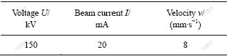
�ѺϽ�ƽ����������ӵĹ��ղ������ڱ�1������ǹ��ն�Ϊ2.0��10-4 Pa����������ն�Ϊ2.0��10-3 Pa������������۽�������������ʱ����۵ĵ�������ֱ�ڹ���ƽ����z�����������䣬��������x�Ḻ����ֱ�߽����γ����ĶԽӽ�ͷ��

ͼ1 ����Ԫ��ֵģ������ʾ��ͼ
Fig.1 Finite element mesh used for numerical simulation
��1 ���������ӹ��ղ���
Table 1 Parameters of electron beam welding
1.2 �����¶ȳ�����Ԫ����ģ��
����������ʱ������С��ЧӦ��ʵ�ʺ�����״������Բ����Դģ�ͼ��㺸�Ӳ�λ�������룬������Ч��ȡΪ0.9[11-12]��
������������������н��У������ڶ�����ֻ�����ȷ��䡣�������������ڵĶԳ���Ϊ���ȱ߽�������������ͨ������ЧӦ��Ԫʩ�ӷ����غɣ����ϵķ��������¶����Ӷ����ӡ�ͨ�����Ӻ����۳ؽ������ȵ����������۳���Һ��Ķ�������ɢ���á������¶ȳ���Ӱ��ͨ������¶������ڱ��ȵľ��ȱ仯ʵ�֡�TC4�ѺϽ�0~500 ����ȴ����ʡ�������������[13]��ȡ��ͨ������֪��������������ϣ�ȷ�����ϸ��·�Χ�������Բ���ֵ��
1.3 ����Ӧ��������Ԫ����ģ��
�����ȶԺ����¶ȳ���Ӱ����Խ�������˲���˳����Ϸ������Ƚ����¶ȳ��ķ�����Ȼ��ͬʱ�̵Ľڵ��¶���Ϊ���غ�ʩ�ӵ��ṹ�ϣ��Ӷ�ʵ�ֺ���Ӧ����������Ԫ���㡣������Ӧ������ʱ�IJ���ģ��ѡΪ�ȣ������ԣ�������ѭVon Mises������
���ڽṹ�ĶԳ��ԣ���������ֱ�ڶԳ�ƽ���λ�ơ�TC4�ѺϽ����䷢����Լ980 �棬��ʱ���ϵ��������ܵͣ����Ҧ¡���ʱ���������仯ԼΪ0.17%�����Լ���ʱδ�������Ӧ����Ӱ�졣���ϲ�ͬ�¶��µ��������ޡ�����ģ������ѧ���ܲ���ȡ������[13]��
2 ��������ʵ����֤
2.1 �¶ȳ������������
ͼ2��ʾΪ���ӿ�ʼ�����˶�10 sʱ�ϱ�����¶ȳ��ֲ���ͼ����ͼ2���Կ����������¶ȸ���800 ����������ں�������������ຸ��������3.5 mm��(��y=![]() 3.5 mm��Χ��)��������(��x��)��������ֱ������������¶���ߣ���2 640 �棬����TC4�ѺϽ�������¶ȡ���Դǰ���¶��ݶȴ������ܼ�����Դ���¶��ݶ�С�������߳���������Բ��״���ں���(��y��)�������뺸�������߾�������ӣ��¶����͡��۳����ϱ���ʵ��͵����ηֲ�������Դ�ƶ������ϣ��۳س�Լ7.5 mm���ڴ�ֱ��Դ�ƶ������ϣ��۳ص�������Լ2.1 mm��
3.5 mm��Χ��)��������(��x��)��������ֱ������������¶���ߣ���2 640 �棬����TC4�ѺϽ�������¶ȡ���Դǰ���¶��ݶȴ������ܼ�����Դ���¶��ݶ�С�������߳���������Բ��״���ں���(��y��)�������뺸�������߾�������ӣ��¶����͡��۳����ϱ���ʵ��͵����ηֲ�������Դ�ƶ������ϣ��۳س�Լ7.5 mm���ڴ�ֱ��Դ�ƶ������ϣ��۳ص�������Լ2.1 mm��

ͼ2 �ϱ����¶ȳ��ֲ���ͼ
Fig.2 Temperature contour of upper surface
ͼ3��ʾΪx=60 mm���뺸�������ߴ�ֱ�ĺ�����ڹ����ϱ��溸�����ĺ;ຸ�������߲�ͬ��������ѭ������ͼ3���Կ���������Դ��û��������ǰ��������¶ȶ�������Χ���ʵ��¶ȣ��ڵ���������ֱ�����������¶ȼ��������ﵽ����¶ȣ����Ź�����ǰ�ƶ���һ���溸�����ĵ��¶�Ѹ���½�����һ���溸���Ա߸���ͨ���ȴ��������¶������ߣ��뺸��������ԽԶ���ﵽ�ֲ�����¶�����ʱ��Խ��������¶�ҲԽ�͡��ຸ��������2��4��8 mm��������¶ȷֱ�Ϊ1 630��728��352 �棬���ַ�ӳ�˵���������ʱ�������к;ֲ����µ��ص�[14-15]��
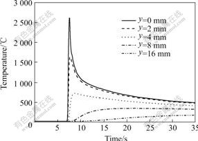
ͼ3 ����������ʱ��ͬλ�õ���ѭ��
Fig.3 Thermal cycles at different locations in electron beam welding condition
2.2 Ӧ���������������
ͼ4��ʾΪx��60 mm���뺸�������ߴ�ֱ�ĺ�������ϱ����1/2��ȴ�����Ӧ���ķֲ������Կ������������Ӧ���ں���ͽ�����Ϊ��Ӧ������������������������Ӧ��ֵΪ670 MPa��ԼΪTC4�ѺϽ�������������70��������1/2��ȴ�������������Ӧ��ֵΪ905 MPa���ӽ����ϵ��������ޡ��ڽ�������Ե�ຸ��������4 mm���������Ӧ��ֵѸ�ٶ�����������Ӧ��ת��ΪѹӦ�����ڴﵽ���ѹӦ��ֵ-125 MPa�����仯�����������������㡣�������Ӧ���ڹ������溸��ͽ�����ΪѹӦ�������ֵԼΪ-150 MPa������1/2��ȴ�Ϊ��Ӧ�������ֵԼΪ150 MPa��ƽ���ڴ�ͳ�绡�����Ӻ������Ӧ���ں���ͽ�����ͨ��Ϊ��Ӧ��������������ʱ�����ٶȿ죬��ȴ�ٶȴ�TC4�ѺϽ��۵�ߣ����ǵ���ϵ����Ϊ�ֵ�1/2������Դ�����̹����й������ĵ��¶���Ը������±�����¶ȣ�������ȴ�����Ľ��������ܵ���Χ��������Լ���±��溸��ͽ������ĺ������Ӧ��ΪѹӦ���������г��������Ӧ���ͺ������Ӧ���⣬�����ڲ��ɺ��ӵĺ�ȷ����ϵĴ�ֱ����Ӧ������ͼ4��֪����ֱ����Ӧ���ڹ������溸��������Ӧ��ֵ��С�������žຸ�������ߵľ���������С���ڹ��������������ĸ�Ľ��紦����ֱ����Ӧ��ֵ��200 MPa��Ϊ-240 MPa���ڹ���1/2��ȴ���ֱ����Ӧ���ں�����Ϊ��Ӧ�������ֵԼΪ234 MPa��
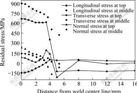
ͼ4 ����Ӧ���غ��������ߴ�ֱ����ķֲ�
Fig.4 Plots of residual stresses with distance away from weld centerline
ͼ5��ʾΪ����Ӧ���ڹ����ϱ����1/2��ȴ������������ϵķֲ����ߡ���ͼ5���Կ��������������Ӧ��ֵ�ں����в����������ȶ����ں������˲�λ���������Ӧ���ɺ㶨ֵ�����㡣����1/2��ȴ������������ȶ���������������Ӧ��ֵ�ӽ����ϵ��������ޡ��������Ӧ���ڹ������溸�����������������ΪѹӦ�����������˵�ѹӦ��ֵ�ӽ����ϵ��������ޣ���β��Ӧ�����ֵ��-921 MPa���������Ӧ���ڹ���1/2��ȴ����������ߵ�����ΪѹӦ�����в�Ϊ��Ӧ�����ȶ�ֵԼΪ150 MPa����ͼ5����֪����ֱ����Ӧ���ں��������ߵ�����ΪѹӦ�����м�Ϊ��Ӧ��������1/2��ȴ������������ϴ�ֱ����Ӧ�����ȶ�ֵ�ߴ�233 MPa��
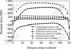
ͼ5 ����Ӧ���ں����������ϵķֲ�
Fig.5 Plots of residual stresses along weld centerline
�����ϵķ�����֪��12 mm��TC4�ѺϽ�ƽ����������Ӻ����Ӧ�����������Ӧ��Ϊ������ֵ���������Ӧ�����зֲ��ں�������������ຸ��������4 mm�ĺ���ͽ������ڡ�����1/2��ȴ������������ϵ����������Ӧ��ֵ�������溸�����˵ĺ������ѹӦ��ֵ�ӽ����ϵ��������ޡ��ڹ������ĺ���ͽ�����������Σ�յľֲ���ά������Ӧ��״̬��
2.3 ʵ����֤
Ϊ����֤12 mm���ѺϽ�ƽ������������¶ȳ���Ӧ������ά����Ԫ��ֵģ�����������ȷ�ԣ�������ص�ʵ�鲢����С���ͷŷ��Բ���Ӧ�����м�⣬�Լ��ߴ缰������������ֵģ��������������ͬ��
ͼ6��ʾΪ��������������ĺ����ò����ͼ6��֪�����ǵ��͵��Ͽ���խ�Ķ��κ��죬�ϱ������Ϊ4.1 mm���±������Ϊ2.2 mm����ͬ��ֵģ��������ϱ���4.2 mm���±���2.1 mm���¶ȴﵽTC4�ѺϽ��̬�����¶�1 540 ��Ľ������һ�¡�

ͼ6 ������������������ò
Fig.6 Macrograph of fusion zone in transverse section
����С���ͷŷ�ʵ������CCZ-1��������̨�ڱ��ⲿλ��ף�����Ϊ4.5 mm����Ϊ2 mm��С�ӹ��ô��Ľ�����ͬ���еIJ���Ӧ�������ͷţ�ԭ�еIJ���Ӧ��Ҳʧȥƽ�⡣��ʱ����Χ������һ�������ͷ�Ӧ�䣬���С�뱻�ͷŵ�Ӧ������Ӧ�ġ���BE120-2CA-1K����Ӧ�仨��CM-1A-10��̬����Ӧ���Ƕ��ͷŵ�Ӧ����м�⣬ʵ���õ�������Visual Fortran���Ա��Ƴ����������㺸�Ӳ���Ӧ����
ͼ7��ʾΪ12 mm���ѺϽ�ƽ������������Ӧ���ͺ������Ӧ����ʵ�����ͼ������ĶԱȡ���ͼ7���Կ���������Ԫ��������С�����IJ���Ӧ������ֲ����ɻ���һ�£�֤��������Ԫ��ֵ����ģ�͵���ȷ�ԡ����ǰ�Ժ�����ߵĴ�ĥ���ܵ��º��������������Ӧ���ͷţ����������Ӧ�����Խ��С�ڼ���ֵ���������Ӧ�������ܵ�������ȴʱ�ĺ���������Ӱ�죬����ͬ���������������������ڲ���ͬ����ȴ�����Լ��������йأ���ֵ���������ģ�͵ļ���ʵ��ͼ���������һ�����졣

ͼ7 ����ͺ������Ӧ����ʵ�����ͼ������ĶԱ�
Fig.7 Plots of numerical and experimental results: (a) Longitudinal residual stress; (b) Transversal residual stress
3 ����
1) ������12 mm��TC4�ѺϽ�ƽ����յ����������¶ȳ���Ӧ��������ά����Ԫ��ֵ����ģ�ͣ�������ͬʵ�����������õ�һ���ԣ�֤��������Ԫ��ֵ����ģ�͵���ȷ�ԡ�
2) 12 mm���ѺϽ�ƽ����յ���������ʱ�����������ں�������������ຸ��������3.5 mm�������ڣ������۳سʵ��͵����ηֲ���ģ��ĺ�����ò��ʵ�����Ǻ����á�
3) 12 mm���ѺϽ�ƽ����յ��������Ӻ�IJ���Ӧ�����������Ӧ��Ϊ������ֵ���������Ӧ�����зֲ��ں�������������ຸ��������4 mm�ĺ���ͽ������ڡ�����1/2��ȴ������������ϵ����������Ӧ��ֵ�������溸�����������˵ĺ������ѹӦ��ֵ�ӽ����ϵ��������ޡ�
4) �����г��������Ӧ���ͺ������Ӧ���⣬�����ڲ��ɺ��ӵĺ�ȷ����ϵĴ�ֱ����Ӧ������ֱ����Ӧ�����ֵ�ߴ�233 MPa���ڹ������ĺ���ͽ����������˽ӽ��������ľֲ���ά������Ӧ��״̬��
REFERENCES
[1] Caiazzo F, Curcio F, Daurelio G, et al. Ti6Al4V sheets lap and butt joints carried out by CO2 laser: Mechanical and morphological characterization[J]. Journal of Materials Processing Technology, 2004, 149(1/3): 546-552.
[2] Casalino G, Curcio F, Capece M F M. Investigation on Ti6Al4V Laser welding using statistical and Taguchi approaches[J]. Journal of Materials Processing Technology, 2005, 167(2/3): 422-428.
[3] Barreda J L, Santamaria F, Azpiroz X, et al. Electronbeam welded high thickness Ti6Al4V plates using filler metal of similar and different composition to the base plate[J]. Vacuum, 2001, 62(2/3): 143-150.
[4] Huang C C, Pan Y C, Chuang T H. Effects of post-weld heat treatments on the residual stress and mechanical properties of electron beam welded SAE 4130 steel plates[J]. Journal of Materials Engineering and Performance, 1997, 6(1): 61-68.
[5] Ferro P, Zambon A, Bonollo F. Investigation of electron-beam welding in wrought Inconel 706-experimentaland numerical analysis[J]. Materials Science and Engineering A, 2005, 392(1/2): 94-105.
[6] Jha A K, Arumugham S. Metallographic analysis of embedded crack in electron beam welded austenitic stainless steel chemical storage tank[J]. Engineering Failure Analysis, 2001, 8(2): 157-166.
[7] Brauss M E, Pineault J A, Eckersley J S. Residual stress characterization of welds and post weld processes using X-ray diffraction techniques[C]//Proceedings of SPIE, 1998, 3399: 196-204.
[8] Carmignani C, Mares R, Toselli G. Transient finite element analysis of deep penetration laser welding process in a singlepass butt-welded thick steel plate[J]. Computer Methods in Applied Mechanics and Engineering, 1999, 179(3/4): 197-214.
[9] Stone H J, Roberts S M, Reed R C. A process model for the distortion induced by the electron beam welding of a Nickel-based superalloy[J]. Metallurgical and Materials Transactions A, 2000, 31(9): 2261-2273.
[10] �� ��, ��ʿ��, ���̶�, ��. �ѺϽ�ƽ����������Ӳ���Ӧ����ֵ����[J]. ���ն���ѧ��, 2001, 16(1): 63-66.
LIU Min, CHEN Shi-xuan, KANG Ji-dong, et al. Numerical model for the temperature and stress fields of moving EBW in titanium alloy plates[J]. Journal of Aerospace Power, 2001, 16(1): 63-66.
[11] Koleva E. Electron beam weld parameters and thermal efficiency improvement[J]. Vacuum, 2005, 77(4): 413-421.
[12] ������, �����, ���Ǿ�, ��. Բ����Դģ�͵ĵ����������¶ȳ���ֵģ��[J]. �纸��, 2005, 35(7): 39-42.
HU Mei-juan, LIU Jin-he, WANG Ya-jun, et al. Finite element analysis of temperature field in electron beam welding of titanium[J]. Electric Welding Machine, 2005, 35(7): 39-42.
[13] �й����ղ����ֲ�༭ίԱ���. ���ղ����ֲ�[M]. ����: �й���������, 2002: 104-132.
Aeronautical materials handbook editorial community. Aeronautical materials handbook[M]. Beijing: Chinese Standards Press, 2002: 104-132.
[14] Stone H J, Withers P J, Holden T M, et al. Comparison of three different techniques for measuring the residual stresses in an electron beam-welded plate of Waspaloy[J]. Metallurgical and Materials Transactions A, 1999, 30A(7): 1797-1808.
[15] Ho C Y. Fusion zone during focused electron-beam welding[J]. Journal of Materials Processing Technology, 2005, 167(2/3): 265-272.
�ո����ڣ�2007-01-22�������ڣ�2007-05-22
ͨѶ���ߣ������꣬�绰��029-88492624��E-mail��guyue@mail.nwpu.edu.cn; guyue1103@sina.com
ժ Ҫ������ANSYS����Ԫ��������������12 mm��TC4�ѺϽ�ƽ������������¶ȳ���Ӧ��������ά����Ԫ��ֵ����ģ�͡�ģ�Ͳ���Բ����Դ���ǵ���������ʱ��С��ЧӦ�����ϵ���ѧ����ѧ���ܲ������¶ȱ仯�������۳���Һ��Ķ���ɢ��ͨ�����Ⱥ��ȵ��ʵı仯ʵ�֡��������������ѺϽ����������ʱ���۳سʵ��͵����ηֲ�����ֵ���������Ӧ�����зֲ��ں�������������ຸ��������4 mm�������ڣ�ƽ���ڲ����ֽӽ������������ľֲ���ά������Ӧ��״̬��ʵ��õ��ĺ�������ò��С���ͷŷ����ĺ��Ӳ���Ӧ���Լ�����������֤, ʵ�����ͼ������ǺϽϺã�֤��������Ԫģ�͵���ȷ�ԡ�
