
Trans. Nonferrous Met. Soc. China 24(2014) 816-823
Development of multi-channel observation and inversion for IP electrical sounding method
Hai-fei LIU1,2, Jian-xin LIU1,2, Rong-wen GUO1,2, Xiao-zhong TONG1,2, Lu GONG1, Yan-hua PENG1
1. School of Geosciences and Info-Physics, Central South University, Changsha 410083, China;
2. Key Laboratory of Nonferrous Resources and Geological Hazard Detection of Hunan Province, Central South University, Changsha 410083, China
Received 30 December 2012; accepted 6 May 2013
Abstract:
In order to improve the exploration effect of deep non-ferrous mineral resources, multi-channel observation methods for induced polarization (IP) electrical sounding data and their inversion imaging technology are studied. First of all, four multi-channel observation methods are developed based on conventional IP electrical method, namely three-electrode and four-electrode arrays of unilateral and bilateral current transmitting. Then the maximum smoothness constrained inversion method of the least squares sense for IP electrical sounding data is proposed, and the inversion software is programmed. Finally, the simulation and inversion results of geo-electrical model for the proposed observation methods are analyzed. And the comparison results show that three-electrode array of bilateral current transmitting gives the best result, but the intensity in field work is larger than others; unilateral three-electrode and four-electrode arrays give the better results. Taking detection results and convenience of field exploration work into consideration, these two methods are more suitable for practical application; bilateral observation method of four-electrode array is not suitable for the detection of the steep ore bodies.
Key words:
IP electrical sounding; multi-channel observation; deep exploration; inversion imaging;
1 Introduction
At present, electromagnetic sounding methods widely used in the exploration of deep mineral deposit, water resources and engineering are audio magnetotelluric method (AMT), controlled source audio magnetotelluric method (CSAMT), high-frequency magnetotelluric imaging method (EH-4) and transient electromagnetic method (TEM). Compared with geometric sounding methods, these methods have advantages of high efficiency, not shielded by high impedance layer, higher resolution for low resistivity layer and so on. And these methods are applied successively in these areas [1-5]. In near-surface application, from dozens of meters to several hundred meters, DC electrical methods, such as high-density resistivity, vertical resistivity sounding and IP electrical sounding, have obvious advantages of easy operation, low cost and relatively sophisticated quantitative inversion interpretation. These methods can obtain information at different depths by increasing the spacing between the current electrodes. However, for deep geological target, traditional observation of these methods (i.e., current electrode spacing is increased exponentially, potential electrode spacing is fixed or increased appropriately), has problems in survey efficiency with a high cost [6]. To this point of view, it is necessary to extend the existing electrical sounding methods with multi-channel techniques to achieve high data acquisition efficiency.
In this work, an IP electrical sounding multi-channel observation system for three-electrode (AMN, MNA) and four-electrode (ABMN, AMNB) arrays is introduced. A receiver system with multi-channels is designed to improve the field data acquisition efficiency. During the survey, potential electrodes, P1, P2, ��, Pn, along a survey line are set up once at a time. The spacing between the adjacent electrodes is determined by the size and depth of buried target, which can vary from a few meters to even hundreds of meters. The spacing can be equal or unequal to only coordinates of the electrode position recorded. The transmitted system is the same as traditional one with the positive and negative current electrodes, placed within potential electrodes, or on one or both sides of them. Three-electrode and four-electrode arrays are re-divided into unilateral and bilateral current electrode mode for convenience in application. In order to obtain information on shallow target, current electrodes are placed within potential electrodes. Finally, these observation methods are proved to be feasible and effective by simulation and inversion of geological models, which can be widely used in deep target exploration.
2 Multi-channel observation methods for three-electrode array
2.1 Unilateral mode of three-electrode array
Multi-channel observation method for three- electrode array is shown in Fig. 1. We may choose this method when the transmitting electrodes are difficult to be arranged on one side of the receiving array. During the survey, all potential electrodes are placed along the survey line. The current electrodes inject current into the underground with the negative electrode located sufficiently far from the survey line (usually more than five times of the maximum distance  ). The survey starts with the positive current electrode placed at the midpoint of potential electrodes P1 and P2. All receiver channels are used to collect the response simultaneously, and the recording points are the midpoints of potential electrodes, with exploration depth equal to the distance between potential electrodes and current electrode. This process is repeated down to the midpoint of Pn-1 and Pn, and the measurement within potential electrodes is completed. To increase the exploration depth, the current electrode C is moved far away gradually by the way of exponentially increasing the spacing from the previous current electrode position. During the movement of the current electrode, current electrode points can be densified appropriately when anomalous data are observed, and also can be rarefied in places where houses, cliffs or other obstacles exist. After the sequence of such measurement completed, the whole receiving array is moved forward a distance of P1Pn (the distance between points P1 and P2), and the current electrode moves backward to the middle point of updated points P1 and P2, from the position of last sequence in the reverse manner as the previous survey. The whole survey is carried out by repeating the above process. Compared with traditional methods, its efficiency of data collection can be greatly improved.
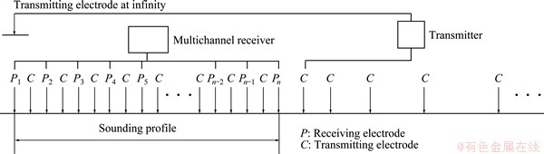
Fig. 1 Unilateral measurement configuration for three-electrode array

Fig. 2 Bilateral measurement configuration for three-electrode array
2.2 Bilateral mode of three-electrode array
Bilateral multi-channel observation for three electrode array is shown in Fig. 2. Compared with the unilateral mode, the amount of work is almost doubled, but the information obtained about the underground is nearly doubled as well, and the ability of distinguishing anomalies will be enhanced. The current electrodes can start at any middle position of two neighbor potential electrodes within the receiving array, then moves backward and/or forward. When the current electrodes are outside the current electrode array, they move in the same manner as the unilateral mode. Once the series of measurement are completed, the whole receiver array is moved forward as the unilateral mode. The new measurement is carried out by moving the current electrodes back to any middle point of two neighbor potential electrodes in the reverse manner as the previous measurement sequence. Then repeat the above process.
3 Multi-channel observation methods for four-electrode array
3.1 Unilateral mode of four-electrode array
Traditional dipole-dipole measurement, with spacing between current electrode pair equal to that of potential electrode pair, is used to detect deep structures via increasing the distance between current and potential electrodes  . Whereas, as the separation coefficient defined by
  increases, the observed signal is attenuated gradually with extraordinary weak signal for =10, which makes it unsuitable for deep geological exploration. In this section, the spacing
  , with
  =n, between two current electrodes is increased to improve the signal-to-noise ratio, and geology information at greater depth can be obtained by increasing the distance from the current electrode B to the potential electrode P1 with
  =m, as shown in Fig. 3. With appropriate m and n, the four-electrode array can be extended to map the subsurface resistivity distribution at great depth.
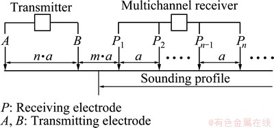
Fig. 3 Unilateral measurement configuration for four-electrode array
During the survey, when each time current is injected into the underground, potential electrodes of n channels with an interval of a for neighbor electrodes, are used to carry out the measurement along the survey line simultaneously, with =n��a, =m��a. After the measurement, both current and potential electrodes are moved together along the survey line, by a distance of a, and the measuring process is repeated until the survey line is completed. However, in practice, it may be difficult to move the whole electrodes, along the survey line. This can be solved by moving the current electrodes by a distance of a, and removing one potential electrode at one end close to the transmitter and placing one on the other end. When the electrodes A and B inject current into the underground and the adjacent potential electrodes Pi and Pi+1 receive signal, generally, apparent horizontal position of data point is (xA+xB+xPi+xPi+1)/4 or (xB+xPi)/2, with apparent vertical exploration depth equal to (xA+xB-xPi-xPi+1)/4. However, this recording way of apparent position can result in the offset of anomaly in the transverse direction when the spacing of is relatively large.
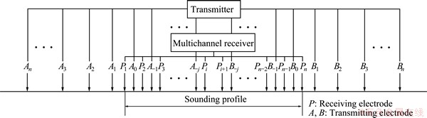
Fig. 4 Bilateral measurement configuration for four-electrode array
3.2 Bilateral mode of four-electrode array
Bilateral multi-channel observation system is illustrated by Fig. 4. Firstly, all the potential electrodes are placed along the survey line, and measurements are carried out for each movement of the two current electrodes, towards two opposite directions from the middle of the potential electrode array. Inside the array, in order to obtain shallow information of the underground, the current electrode spacing increases arithmetically. Outside the array, it increases logarithmically or exponentially, which depends on the data information. The data point measured is horizontally recorded at the midpoint of the adjacent potential electrodes, O, and the vertical apparent depth is the minimum distance of  (the distance between the current electrode A and O) ,
  (the distance between the current electrode B and O)
4 Two-dimensional inversion imaging of IP sounding
Generally the inversion of IP sounding is divided into two steps: firstly, complete the inversion of resistivity data [7], and then complete the inversion of polarizability data on the basis of the fixed underground resistivity parameters. For resistivity inversion, the linear inversion equation of resistivity can be expressed as
A��m=��d (1)
where ��d is the data residual vector, namely, the difference between the measured apparent resistivity and the simulated apparent resistivity in the logarithm (��di=ln ��ai-ln ��ci, i=1, 2, ��, N); ��m represents the correction vector of the model parameter (��mj=ln ��i, j=1, 2, ��, M); A is the partial derivative matrix (aij= ln ��ci/ln ��j); ��j is the resistivity of the jth node.
For 2D inversion process of IP electrical sounding, the problem in Eq. (1) is often underdetermined. To improve the stability of the inversion process and the accuracy of the solutions, some constraints are required to be introduced into the model space [8,9]. The overall constraint can be expressed as
 (2)
(2)
where m is the vector of model parameter; C is the Thkhonov stabilization operator which usually is given in the form of differential, integral, and matrix. The elements of the one-order stabilization operator in matrix form can be defined as [10-12]

where l is the number of adjacent nodes which are connected to the node i and rij is the distance between the node i and j. Combining Eq.(1) with Eq.(2), the objective function �� in the least square sense can be constructed as [13]
 (3)
(3)
For the right side of Eq. (3), the first item is the fitting difference in the data space, and the second item is functional constraint of the model space; �� is the regularized factor. Then the following least-square linear inversion equation can be derived by differentiating both sides of Eq. (3) and setting to zero,
 (4)
(4)
The model parameter modification vector ��m can be calculated by solving Eq. (4) with the variable damping conjugate gradient method [14], which is substituted into the following formula:
 (5)
(5)
A new forecasting model parameter vector m(k) will be obtained. And �� is the correction step, which can be obtained by golden section linear searching method [12]. The above process is repeated until the root-mean- square error between the measured and the simulated data meets the requirements. The root-mean-square error can be expressed as

For polarizability inversion, according to the Seigel induced polarization theory [15], it is assumed that the geoelectrical model can be described by the two physical parameters, namely the conductivity ��(x, y, z) and the polarizability ��(x, y, z). The polarizability is defined in the interval [0, 1], whose variation is much smaller than that of the conductivity. So assuming that the apparent resistivity ��a is the function based on the conductivity ��(x, y, z) as independent variables. When induced polarization exits on the subsurface, it can be expressed as
 (6)
(6)
where  is the equivalent apparent resistivity, and �� is the polarizability. Again assuming that the underground model consists of M pieces of rock and ore with different ��j and ��j (j=1, 2, ��, M). The right side of Eq. (6) is unfolded by Taylor series with respect to conductivity ��, and then the item is omitted which is higher than second order. So can be described as
 (7)
(7)
Then, according to the equivalent apparent resistivity formula, the response can be given as

 (8)
(8)
After the second approximation, Eq. (8) can be written as
 (9)
(9)
So, the response on the point ith is [16]
 ,
,
i=1, 2, ��, N (10)
The linear approximation relationship Aij between the polarizability and the apparent polarizability is the partial derivative of the observed apparent resistivity to the model resistivity, which has been obtained after the resistivity inversion ends. Equation (10) can be written as
 (11)
(11)
where ��a is the measured apparent polarizability and �� is the vector of model parameters. Similarly, based on the regularized resistivity inversion method, background smooth constraint information ��b is introduced into Eq. (11) and the linear inversion equation can be expressed as [17]
 (12)
(12)
The parameter �� will be obtained by solving Eq. (12) with conjugate gradient method and the amount of calculation is small.
The computing procedure of 2D inversion of IP sounding can be summarized as shown in Fig. 5.
5 Calculation and analysis of model
For further comparative analysis on the detecting capacity of four multi-channel observation methods, numerical simulation and inversion imaging of a geoelectric model are carried out as follows. It is assumed that there is a tilt vein orebody with resistivity of 5 ����m, and polarizability of 10% in the underground half-space. The resistivity is 100 ����m and polarizability is 2% on the overlying strata of orebody. The resistivity and polarizability of surrounding rock beneath the orebody are 500 ����m and 3% respectively; the resistivity and polarizability of near-surface formation are 50 ����m and 1% respectively. The details for the geoelectric model are shown in Fig. 6(a).
Receiver system of this model comparison test has 21 channels, which are placed along the survey line from 0 to 800 m at equal interval of 40 m. Taking the complexity and variability of field work in practice into consideration, transmitter system is designed as 2 channels, and the current point gradually increases from the minimum spacing,  m to the maximum spacing,
  m. After the data acquisition of a receiving array accomplished, the receiving array can be moved forward depending on the exploration requirements. If necessary, the current point should gradually reduce from the maximum spacing to the minimum spacing, and then data acquisition of 40 IP sounding points are completed. Compared with conventional vertical electrical sounding methods, its efficiency can be improved by 20 times.
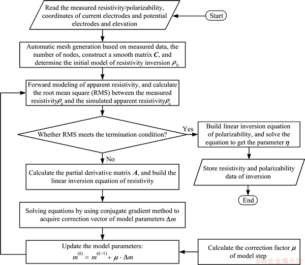
Fig. 5 Flow chart of 2D inversion imaging of IP electrical sounding data
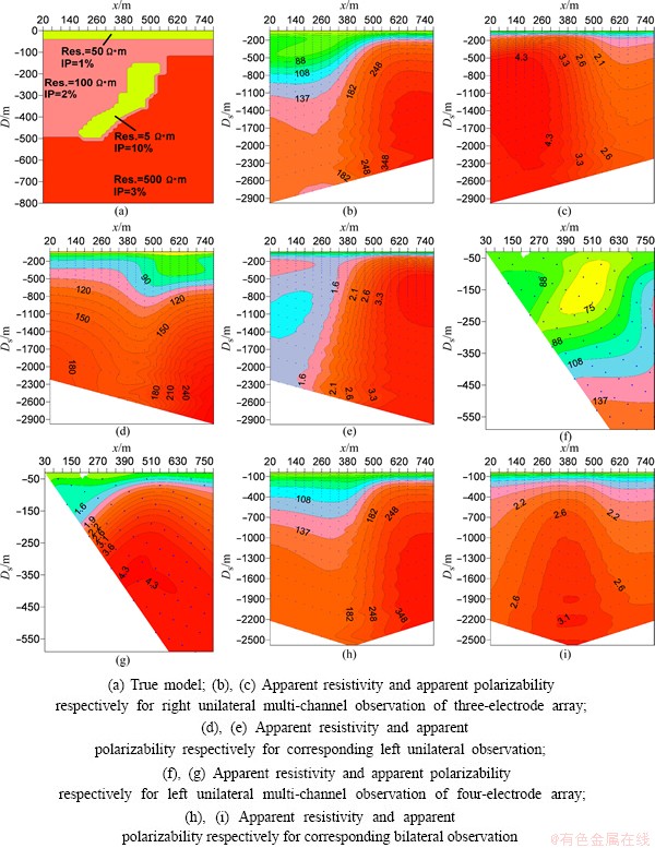
Fig. 6 Pseudo section for different observation methods
Based on the geoelectric model shown in Fig. 6(a), the finite element method is applied to simulating apparent resistivity and apparent polarizability data of four observation methods above, and plot pseudo-section maps, as shown in Figs. 6(b)-(i). The figures show that pseudo section for four observation methods reflect the existence of underground anomalous structure, but the buried depth and shape of the anomalous body are obscure, especially the vertical resolution is lower. In the aspect of deduction and interpretation of the buried scope of the ore body, it is difficult to obtain reliable interpreted results by only analyzing the pseudo-section maps of apparent resistivity and apparent polarizability.
In order to improve the detection results of the four exploration methods, 2D inversion imaging of simulated IP data shown in Figs. 6(b)-(i) are carried out by the method described here and the results are shown in Figs. 7(a)-(h). The results show that bilateral multi-channel observation methods for three-electrode array give the best result on the buried depth and shape of anomalous body. The main reason is that it belongs to a differential device, the lateral resolution is high and the quantity of observed data is relatively large, which is substantially twice that of other observation devices. Unilateral multi-channel methods for three-electrode and four-electrode array give better results. Taking these aspects into consideration, such as detection results and convenience of field exploration work, these two methods are worth widely using in practice. Bilateral multi-channel observation methods for four-electrode array give relatively poor results and lower lateral resolution, which is decided by the features of integral observation device itself and it is not suitable for the detection of the steep orebody. For unilateral observation method of four-electrode array, in order to further improve its detection results through obtaining the optimum coupling between observation device and abnormal body, so some research work on how to make reasonable choice of coefficients m and n according to the approximate depth of underground objects needs to be done.
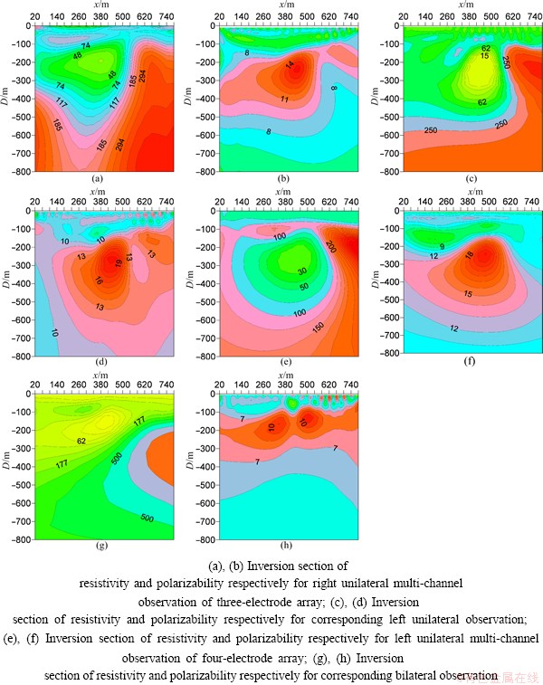
Fig. 7 Inversion section of resistivity and polarizability data of different observation methods for Fig. 6
6 Conclusions
1) Unilateral and bilateral multi-channel observation methods for three-electrode and four-electrode arrays are developed, and the efficiency of data acquisition can be improved greatly.
2) Modeling results show that observation methods proposed are able to demonstrate the existence of underground anomalous structure. However, the buried depth and shape of the underground target are relatively vague. For the four observation modes, inversion imaging interpretation of simulated IP data is carried out. Inversion results show that bilateral multi-channel observation method for three-electrode array gives the best result, but the intensity in field work is larger than others; unilateral multi-channel methods for three- electrode and four-electrode arrays give better results. Taking detection results and convenience of field exploration work into consideration, the methods are suitable for practical application; bilateral multi-channel observation method for four-electrode array gives relatively poor results, especially it is not suitable for the detection of the steep orebodies. In the field applications of the four observation methods, it will be a better solution to the exploration problems for mineral resources with great depth by means of taking the site conditions and the occurrence of orebodies into consideration, and combing with the present inversion imaging technology.
3) For unilateral mode of four-electrode array, which belongs to a differential device, it has a relatively high lateral resolution for anomalous bodies. However, for underground objects at different depth, choices of coefficients m and n, and arrangement of the current electrodes A and B will influence the exploration effect, which needs still further study.
References
[1] YU Nian, PANG Fang. Application of audio magnetotelluric sounding in the geothermal exploration [J]. Hydrogeology & Engineering Geology, 2010, 37(3): 135-138. (in Chinese)
[2] XIAO Zhao-yang, HUANG Qiang-tai, ZHANG Shao-jie, XIA Bin, WANG Bao-lin. Application of EH4 electromagnetic image system in mineral resource exploration��An example from the Huangjindong gold ore deposit [J]. Geotectonica et Metallogenia, 2011, 35(2): 242-248. (in Chinese)
[3] YU Chuan-tao, LIU Hong-fu, YU Yan-mei, MA Zhi-fei. Application of CSAMT method in buried fault detecting in coal mine [J]. CT Theory and Application, 2010, 19(1): 28-33. (in Chinese)
[4] ZHOU Ping, SHI Jun-fa. New progress and application of transient electromagnetic method in the buried ore deposit exploration [J]. Geology and Exploration, 2007, 43(6): 63-69. (in Chinese)
[5] XI Zheng-zhu, ZHU Wei-guo, ZHANG Dao-jun, ZHANG Liang-liu, FENG Wan-jie, DENG Zhi-gang. Indirectly exploit buried deposits of rich iron by audio frequency magnetotelluric method [J]. The Chinese Journal of Nonferrous Metals, 2012, 22(3): 928-933. (in Chinese)
[6] Teaching and research section of metal geophysical exploration, Wuhan Institute of Geology. Electrical prospecting tutorial [M]. Beijing: Geology Press, 1991. (in Chinese)
[7] TRIPP A C, HOHMANN G W, SWIFT C M. Two dimensional resistivity inversion [J]. Geophysics, 1984, 49(10): 1708-1717.
[8] CONSTABLE S C, PARKER R L, CONSTABLE C G. Occam��s inversion: A practical algorithm for generating smooth models from electromagnetic sounding data [J]. Geophysics, 1987, 52(3): 289-300.
[9] de GROOT-HEDLIN C, CONSTABLE S C. Occam��s inversion to generate smooth, two-dimensional models from magnetotelluric data [J]. Geophysics, 1990, 55(12): 1613-1624.
[10] RUAN Bai-yao, YUTAKA M, XU Shi-zhe. Least square 2D inversion for induced polarization data [J]. Earth Science-Journal of China University of Geosciences, 1999, 24(6): 619-624. (in Chinese)
[11] RUAN Bai-yao, YUTAKA M, XU Shi-zhe. 2-D inversion programs of induced polarization data [J]. Computing Techniques for Geophysical and Geochemical Exploration, 1999, 21(2): 116-124. (in Chinese)
[12] LIU Hai-fei. Linear and nonlinear inversion methods research on direct current IP measurements [D]. Changsha: Central South University, 2007. (in Chinese)
[13] LIU Hai-fei, RUAN Bai-yao, LIU Jian-xin. 2D self-adaptive regularization inversion with vertical Induced polarization sounding data [J]. Journal of Tongji University: Natural Science, 2009, 37(12): 1685-1690. (in Chinese)
[14] LIU Hai-fei, RUAN Bai-yao, LIU Jian-xin. The conjugate gradient algorithm of variational damping and its capability analysis [J]. Progress in Geophysics, 2008, 23(1): 89-93. (in Chinese)
[15] SEIGEL H O. Mathematical formulation and type curves for induced polarization [J]. Geophysics, 1959, 24(3): 547-565.
[16] OLDENBURG D W, LI Y. Inversion of induced polarization data [J]. Geophysics, 1994, 59(6): 1327-1341.
[17] LIU Hai-fei, LIU Jian-xin, GUO Rong-wen. Efficient inversion of 3D IP data for continuous model with complex geometry [J]. Journal of Jilin University: Earth Science Edition, 2011, 41(4): 1212-1218. (in Chinese).
��������ͨ���۲ⷽ�������ݳ���
������1,2��������1,2��������1,2��ͯТ��1,2���� ¶1������1
1. ���ϴ�ѧ �����ѧ����Ϣ����ѧԺ����ɳ 410083��
2. ���ϴ�ѧ ��ɫ��Դ������ֺ�̽�����ʡ�ص�ʵ���ң���ɳ 410083
ժ Ҫ��Ϊ�˸��������ɫ���������Դ�Ŀ�̽Ч�����Լ�������ͨ���۲ⷽ�������ݳ�����չ���о������ȣ����4�ֶ�ͨ���۲ⷽ�����������ߺ�˫�߹�����������ļ�ģʽ��Ȼ������С���������¼���������⻬Լ�����ݷ��������Ʒ��ݳ���ͨ����ģ��ͷ��ݽ�����з�����˫�߹���������۲ⷽ����̽Ч����ѣ���Ұ���ǿ�Ƚϴ��߹�����������ļ��۲ⷽ���Ŀ�̽����Ϻã���̽��Ч����Ұ��ʩ���ĽǶȿ��ǣ����Ǹ��ʺ���ʵ��Ӧ�ã�˫�߹�����ļ��۲ⷽ��������̽���״�϶�������״���塣
�ؼ��ʣ���������ͨ���۲⣻�����̽�����ݳ���
(Edited by Hua YANG)
Foundation item: Project (41174102) supported by the National Natural Science Foundation of China
Corresponding author: Hai-fei LIU; Tel: +86-13873378983; E-mail: liuhaifei@126.com
DOI: 10.1016/S1003-6326(14)63130-7
Abstract: In order to improve the exploration effect of deep non-ferrous mineral resources, multi-channel observation methods for induced polarization (IP) electrical sounding data and their inversion imaging technology are studied. First of all, four multi-channel observation methods are developed based on conventional IP electrical method, namely three-electrode and four-electrode arrays of unilateral and bilateral current transmitting. Then the maximum smoothness constrained inversion method of the least squares sense for IP electrical sounding data is proposed, and the inversion software is programmed. Finally, the simulation and inversion results of geo-electrical model for the proposed observation methods are analyzed. And the comparison results show that three-electrode array of bilateral current transmitting gives the best result, but the intensity in field work is larger than others; unilateral three-electrode and four-electrode arrays give the better results. Taking detection results and convenience of field exploration work into consideration, these two methods are more suitable for practical application; bilateral observation method of four-electrode array is not suitable for the detection of the steep ore bodies.
