
Trans. Nonferrous Met. Soc. China 25(2015) 926-935
3D FEM simulation of flow velocity field for 5052 aluminum alloy multi-row sprocket in cold semi-precision forging process
Wang-jun CHENG1, Cheng-zhong CHI1, Yong-zhen WANG1, Peng LIN1, Ri-hong ZHAO1, Wei LIANG1,2
1. College of Materials Science and Engineering, Taiyuan University of Technology, Taiyuan 030024, China;
2. Key Laboratory of Interface Science and Engineering in Advanced Materials, Ministry of Education, Taiyuan University of Technology, Taiyuan 030024, China
Received 23 April 2014; accepted 10 September 2014
Abstract:
Based on the design of the multi-row sprocket with a new tooth profile, a cold semi-precision forging process for manufacturing 5052 aluminum alloy multi-row sprocket was presented. Through simulating the forging process of 5052 aluminum alloy sprocket billet with 3D rigid-viscoplastic FEM, both the distributions of flow velocity field in axial (UZ), radial (UR) and circumferential (U��) directions and the curves of velocity component in different deformation regions were respectively obtained. By comparison and analysis of the velocity varying curves, the velocity component relation conditions for filling the die cavity were clarified. It shows that when the die cavity is almost fully filled, the circumferential velocity U�� increases sharply, implying that U�� plays a key role in fully filling the die cavity.
Key words:
multi-row sprocket; cold semi-precision forging; 5052 aluminum alloy; flow velocity field; 3D FEM;
1 Introduction
A multi-row sprocket with flanges (Fig. 1) is commonly utilized in the driving system of the machinery and equipment, such as bicycles, motorcycles, tanks, scraper conveyers and printers, and is mainly used for the transmission of the rotary motion between two shafts. Sprockets are conventionally produced by hobbing process to form the teeth and followed by heat treatment to improve the hardness, which are material wasting, time consuming, mechanical property deteriorating and productivity decreasing. THIPPRAKMAS [1] presented the fine-blanking process to manufacture single-row sprocket. The number of process operations and the production time were reduced with this method. LEGAULT et al [2] investigated aluminum alloy powder metal extrusion to manufacture and test the sprocket including compaction, sintering and heat treatment. A compacting technology of the housing sprocket in one single compacting stroke was established by TAKAGI et al [3] and the dimensional tolerances of the sprocket were maintained. However, those methods have a higher production cost, greater energy consumption, large-scale extending and utilizing difficulty. The studying and manufacturing for sprockets have been reported by many researchers from various aspects, but no attempt has been made so far to use cold precision forging technology to produce aluminum alloy multi-row sprockets.
There are two categories of aluminum alloys used in structural and plant applications that are non-heat- treatable and heat-treatable. 5052 aluminum alloy is basically an Al-Mg alloy (Mg content is in the range of 2.2%-2.8%) and is non-heat-treatable [4]. The cold precision forging of multi-row sprocket with 5052 aluminum alloy is a new-complex process with severe plastic deformation, which requires good formability of the billet material at a lower temperature, reasonable forging process, proper structural design of the die and less boundary non-linearity [5,6]. To some extent, the forging process may determine the development level of multi-row sprocket manufacturing industry. Most importantly, traditional profile of tooth top for the multi-sprocket is sharp and small, which may result in stress concentration and crack of the die cavity in cold forging. At present, there is no successful precedent for actual production application. The technology of multi-row sprocket cold precision forging with 5052 aluminum alloy has been still remained in experimental exploration stage.

Fig. 1 Photos of multi-row sprocket
Velocity field is mainly used to investigate the load requirements and the process parameters in spline and spur gear forging [7, 8], which plays an important role in filling the die cavity in precision forging and determines the filling ability of work-piece. However, it is extremely difficult to obtain the velocity fields by experiments in different deformation directions and specific numerical values in various deformation zones. Using a straight tapered tooth profile, CAN and MISIRLI [9] developed an upper bound solution for the lateral extrusion of spur gear form and the proposed velocity field was not discontinuous on the surface of the tapered tooth. CHOI et al [10] also modeled a new tooth profile including an involute curve and a circular arc fillet instead of the tapered profile to obtain a more practical method to analyze velocity fields in spur gear forging. A kinematically admissible continuous velocity field was proposed for the analysis of three-dimensional forging by ZHAO et al [11]. WANG et al [12] also developed a new asymmetry tooth profile for the sprocket by establishing mathematical and dynamic models aiming to reducing the impact of the flow velocity field between rollers and sprocket. Theories above may be far from the actual application in cold precision forging of the multi-row sprocket. Because it is difficult to quantize specific numerical values in various deformation zones of the billet. With the development of FEM and computer technology, the numerical simulation has become an effective tool to decrease the cost and the time for analyzing and quantizing velocity field in cold precision forging of the multi-row sprocket [13].
In the present work, a new-simple type of sprocket tooth profile instead of the traditional one was designed to reduce the stress concentration and crack of die cavity. Numerical simulation using software DEFORM-3D V6.1 was performed to critically verify the distributions of flow velocity field, the flowability of 5052 aluminum alloy and the filling quantity in various regions. It is expected that the present work will be significant to assess the characteristics of the multi-row sprocket in cold precision forging.
2 Forging process of multi-row sprocket
In general, the forging process depends on material property, geometric shape, dimensional accuracy, surface quality, equipment, etc. The reasonable geometric shape can improve the dimensional accuracy of the forging and reduce the stress concentration and crack of the die cavity. In this work, both the new-simple profile of sprocket tooth and the new forging process were proposed. The part drawing and the forging drawing of a multi-row sprocket are respectively indicated in Fig. 2.
2.1 Design of tooth profile
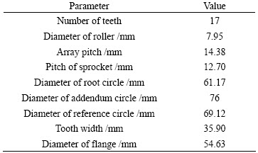
The standard tooth profile of a multi-row sprocket (GB 08A) was adopted to analyze deformation cases in cold semi-precision forging whose detailed parameters are listed in Table 1. The proper design of tooth profile for precision forging die is not only to ensure excellent dimensional accuracy, but also to ensure that the tooth profile is simple and the processing is easy without stress concentrations and cracks [14]. The traditional profile of tooth top for multi-row sprocket is sharp and small, which possesses a large curvature and may lead to stress concentration and crack of the die cavity in cold precision forging. A new sprocket tooth profile is developed to represent traditional tooth profile, which includes the circular arc  , the common tangent MN and the circular arc
  , as shown in Fig. 3.
In the Cartesian coordinate system XOY,  represents the traditional tooth profile of the multi-row sprocket. It is assumed that the sprocket is fixed at the given position, the new tooth profiles in one drawing unit (��/N) are constructed by the circular arc , the common tangent MN and the circular arc . The centers of circle arc and circle arc are respectively the point O1 and the point O2. The circular arc
  and are concentric circles. The center of circular arc is the same as the center of the tooth top O2 and the central point O1 is on pitch circle of the sprocket. The relations of radius are expressed as follows:
 (1)
(1)
where ��1, ��2 are machining allowances; N is the number of teeth; r1, R1 and R2 are the radii of tooth.

Fig. 2 Part drawing (a) and forging drawing (b) of multi-row sprocket (unit: mm)
Table 1 Parameters of multi-row sprocket
2.2 Design of forging process
Based on the design of the multi-row sprocket with a new tooth profile, three cold semi-precision forging processes are discussed in Fig. 4. The advantages and disadvantages of the processes are listed in Table 2. As a resistance, the concave grooves on the flange of multi-row sprocket block the separation of the sprocket forging billet from the bottom die. Therefore, it is difficult to demould from the die cavity with one time in the moving direction of the die. Therefore, the semi-precision forging process in Fig. 4(b) including processing hollow billet, preforming sprocket teeth and machining flange concave grooves is newly established with simpler operation, better die cavity filling, lower cost and higher strength for forging multi-row sprocket. The tool structure is designed as shown in Fig. 5.
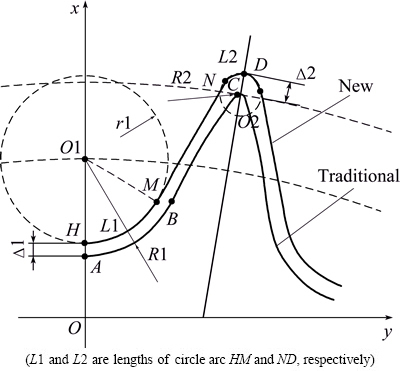
Fig. 3 New tooth profile of sprocket

Fig. 4 Schematic of three forging processes of multi-row sprocket
Table 2 Processing analysis of multi-row sprocket forging


Fig. 5 Schematic of die structure of multi-sprocket in cold semi-precision forging
3 FEM simulation
3.1 FE formulation
The 3D FEM is based on the rigid-viscoplastic variation principle. Usually, the governing equations for the solution of the mechanics of rigid-viscoplastic deformation do not consider the volume force and neglect the elastic deformation of the material [15]. Markov variation principle is applied to obtaining the FE formulations which are related to the total potential energy. It is required among admissible velocity ui that satisfies geometric condition, incompressibility and velocity boundary conditions. The governing FE formulations of rigid-plastic body in equilibrium state of the forging process are described as follows:
Penalty function:
 (2)
(2)
 (3)
(3)
Flow formulation:
 (4)
(4)
where  ,
,  ,
,  ,
,  , ui, SF and V are the effective strain rate, strain rate, volumetric strain rate, effective stress, kinematically admissible velocity field, force surface and the volume of the billet, respectively;
  is the traction stress; K is a large positive constant of penalizing the volumetric strain rate component;
  is the work function.
Equations (2) and (3) are the new penalty function which can explain the generalized variational principle and can be converted to non-linear algebraic equations by utilizing the boundary constraints. Equation (4) can also be converted into non-linear algebraic equations based on the discretization procedure in terms of the arbitrary variation of the velocity.
3.2 Model
Based on the FE formulations above, the flowability of 5052 aluminum alloy sprocket during the cold semi- precision forging was verified by numerical simulation in order to obtain the axial, radial and circumferential velocity fields in filling the die cavity. Constrained shunt hole for the hollow billet whose initial geometry sizes are shown in Fig. 6 was applied to ensuring the die cavity fully filled. Based on the implicit Lagrangian FE code, the commercial FEM package DEFORM-3D V6.1 was used to simulate the flow velocity fields in cold semi- precision forging. Three-dimensional solid models were established with Pro/E 4.0 software, which were assembled and imported to DEFORM-3D software in form of STL files. The 3D FE model of the finish forging operation was constructed in Fig. 7.

Fig. 6 Geometry sizes of initial hollow billet (unit: mm)
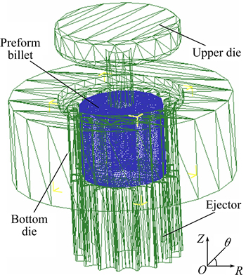
Fig. 7 FE model of semi-precision forging
3.3 Material
Process modelling of large deformation processes such as forging and forming typically requires material flow stress to be fined over a wide range of temperatures and strain rates in quasi-static forming process [16]. In this study, the material of hollow billet was 5052 aluminum alloy (chemical compositions are listed in Table 3) which was chosen from the DEFORM-3D material library. The flow and behavior of the billet material can be traditionally expressed as Eq. (5), which is related to strain, strain rate and temperature. Due to the fact that the influence of room temperature is smaller, above constitutive equation is not precise enough to reflect the cold deformation process of 5052 aluminum alloy.
Table 3 Chemical composition of 5052 aluminum alloy (mass fraction, %)

 (5)
(5)
The appropriate cold deformation for 5052 aluminum alloy in this work was supposed to be the strain rate of 4.0-100 s-1 and initial temperature of 20 ��C because the verification on various flow velocities depended on the same initial set of material data and ignored the influence of room temperature in order to ensure commonality and allow comparison across the material models. For the purpose of describing the constitutive equation with higher accuracy, it is assumed that the material temperature of 20 ��C in high-velocity forming process is nearly unchanged. The Cowper- Symonds model (C-S model) [17] is applied to fitting simple elasto-plastic, strain hardening and strain rate hardening model of 5052 aluminum alloy during cold semi-precision forging process. It is defined as follows:
 (6)
(6)
where �� is the flow stress in high-velocity; ��0 is the flow stress in the quasi-static process;  is the strain rate;
  is the effective strain; K and D are both material constants and
  represents the influence of strain on strain rate sensitivity.
Based on the constant friction law, the friction at contacting interfaces of the billet and the die cavity is assumed to be shear type which is usefull at high pressures and stated as [18]
fs=mk (7)
The friction factor m is theoretically defined as Eq. (8) (R0
1) in ring compression test.
 (8)
(8)
where fs is shear frictional stress; k is shear yield stress; R1 is external diameter of the ring; R0 is inner diameter of the ring; H is the height of the ring and p is the diameter of the neutral surface.
Equation (8) is not sufficient to determine the friction factor m, because it just takes the geometrical dimensions of standard specimen into account. Die materials, billet materials, and experimental conditions are not considered, especially under the conditions with complex friction. The ��inter-object�� window of FE simulation software DEFORM-3D presents the recommended values of friction factor m under various forming conditions. For cold forming with steel dies at room temperature, the recommended value is 0.12. Therefore, the friction factor m takes 0.12 in this work.
3.4 Parameter
The billet ignoring the elastic deformation was meshed with tetrahedral elements. The complete semi-precision forging simulation was performed in 90 steps having displacements for the movement of the upper die in each step equal to 0.2 mm. The velocities of the upper die and the floating bottom die were the same as to be 15 mm/s. It was supposed that the die models were rigid with meshed grids to simulate the temperature conduction. The volume changes between the billet and the dies were compensated. Table 4 lists the parameters of FE model which were inputted to working interface of the software.
Table 4 Parameters of FE model

4 Results and discussion
4.1 Analysis of billet deformation
The cold semi-precision forging process of the 5052 aluminum alloy multi-sprocket can be divided into four stages, namely free upsetting, filling, corner filling and recovery stages, as illustrated in Fig. 8. In free upsetting stage, as the upper die travel increases, the billet compresses axially and bulges radially because the billet does not contact with the bottom die and flows freely in the radial direction. In tooth forming stage, the metal flow becomes much harder due to the friction effect of the bottom die, where interfacial friction between the die and the billet retards its plastic flow and the size of the non-contact areas decreases. In recovery stage, the bottom corner is formed in an even earlier stage with some larger rough selvedges. The radial flow resistance reaches the maximum and the filling in admissible shape areas becomes more difficult. It can be concluded that utilizing Deform-3D FE software to simulate the deformation of sprocket preform above is feasible. Based on the feasibility of billet deformation, 3D FEM with cylindrical coordinates (R, ��, Z) system is used to demonstrate the distributions of flow velocity field for 5052 aluminum alloy sprocket preform.

Fig. 8 Forming profiles in various stages
4.2 Distribution of axial velocity
Figures 9(a), (b) and (c) show the distributions of axial velocity (UZ) during the finishing forging process at different strokes. In free upsetting, flowing velocity decreases in sequence from the top to the bottom of the billet mainly due to the inertia power dissipation that is appreciable in the process of the upper die movement. In addition, micro drum-shape has been created on the external surface of the billet due to the friction effect between the upper die and the billet, as shown in Figs. 9(a) and (b). In recovery stage, as admissible flow areas of the die cavity decrease sharply, flow velocity of the billet reaches the maximum of 221 mm/s in Fig. 9(c). Figure 10(a) illustrates the variation of axial velocity with strokes in different deformation regions. It can be seen that axial velocity increases slowly initially and then remains constant while it increases rapidly in final stage. The core velocity is lower than that of teeth and neutral surface for the sprocket preform. Additionally, their variation trends are basically identical and the flows are heterogeneous, which are related to the thickness of the billet and the movement speed of the upper die.
4.3 Distribution of radial velocity
The distribution of radial velocity (UR) with different strokes presents a central radiation and non-uniform flow, as shown in Figs. 9(d), (e) and (f). It is clear that the radial velocity is much lower when the billet fluid first contacts with the toothed surface of the die cavity due to more constraints in the die cavity. Nevertheless, it is much higher due to flowing freely on the external surface, as shown in Fig. 10(b) (the blue curve). The radial velocity in the core of sprocket preform approximates to zero due to the constraint effect of the mandrel in initial stage. As the upper die continues downward, there presents a neutral shunt surface in the middle of the sprocket preform whose radial velocity is zero, as shown in Fig. 10(b) (the red curve), where the material flows inward inside the neutral surface while flows outward outside the neutral surface. The radial flow velocity in tooth tip of the preform reaches the maximum of 179 mm/s in corner filling stage and the irregular backflow of the billet fluid occurs during recovery stage, as shown in Fig. 9(f).
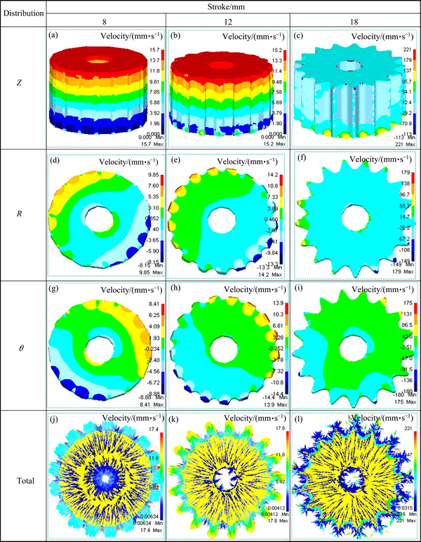
Fig. 9 Distributions of axial (Z), radial (R), circumferential (��) and total velocities (Total) during forging process at different strokes
4.4 Distribution of circumferential velocity
Figures 9(g), (h) and (i) show the circumferential velocity (U��) distribution on the top surface of the hollow billet. The maximum velocity of 180 mm/s is found on the largest surface curvature in the tooth tip which flows outwards during the forging process while the minimum velocity without restriction effect of the central mandrel and the die cavity was presented on the middle surface of the billet. The initial circumferential velocity increases slowly and then remains constant. Finally, the velocity around the preformed teeth increases sharply owing to the die friction effect between the axial and the radial distribution which makes shear friction remain the maximum around the circumferential, as shown in Fig. 10(c).
4.5 Distribution of total velocity
Figures 9(j), (k) and (l) indicate the total velocity (U) distribution on the top surface of the hollow billet and the maximum velocity is 221 mm/s without negative value in the tooth tip. In initial free upsetting stage, external surface of the hollow billet is not affected by the radial restraining stress of the die cavity. Figure 9(j) shows that the billet flows are given a priority to the radial but a subordinate in the axial. As discussed earlier, the die cavity is filled with fluid particles in the external of the billet. Both convex ear-velocity and micro drum-shape occur on the edge of the billet perform in the later forming. According to the law of minimum resistance, billet flow velocity increases sharply in the tooth-groove of the die cavity due to the path with the least resistance when the billet first contacts with the die cavity. However, it decreases sharply owing to the storage effect of the billet fluids in the addendum of the sprocket preform in Fig. 10(d) (the blue curve). In corner filling stage, as the total velocity increases, material fluids are given a priority to the axial flow but a subordinate along the radial, this is because the self-locking of material occurs during the die cavity fully filled. In recovery stage, non-uniformity increases with friction and irregular fluctuations may occur in the peak of billet, as observed in Fig. 9(l).
Figure 11 compares the simulation results of velocity-stroke curves between the tooth top and the tooth groove. The axial velocity (UZ) is much lower than the circumferential (U��) and the radial (UR) velocities when the billet starts to contact with the die cavity. If the upper die stroke is less than 13 mm, the radial velocity (UR) is higher than the circumferential (U��) one on the surface of the billet. By contrast, if the upper die stroke is more than 13 mm, the radial velocity (UR) is slightly lower than the circumferential one (U��). However, the circumferential velocity (U��) increases, which is higher than the radial (UR) and axial (UZ) velocities, and finally reaches the maximum of 42.96 mm/s in corner filling stage because admissible flow areas approximate to zero and the die restriction effect reaches the maximum, which makes billet fluids flow irregularly. Consequently, velocity relations may be obtained by comparing the curves of the axial, radial and circumferential velocities when the upper die strokes vary from 13 to 16 mm (fully filling stage). For the given velocity components UZ, UR and U��, there exists an inequality. If U��>UR>UZ>0, the billet fluids fully fill the die cavity; if UZ>UR>U��>0, almost no billet fluids fill the die cavity; if U��>UZ or U��>UR, the billet fluids incompletely fill the die cavity. All these show that circumferential U�� plays an extremely important role in fully filling the die cavity during the cold semi-precision forging of 5052 aluminum alloy sprocket, the reason for which is that the stress at the billet-die interface is assumed to be shear-friction type.
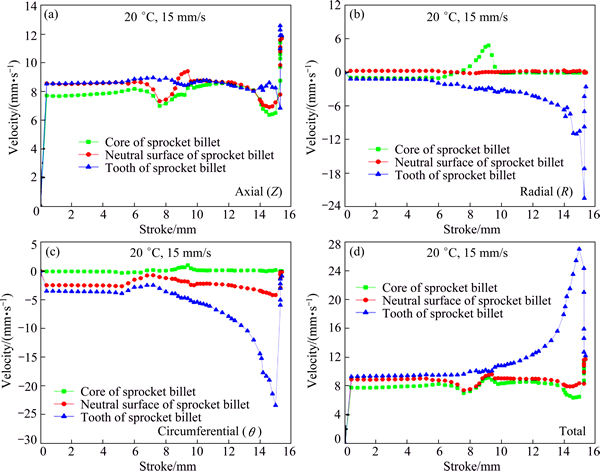
Fig. 10 Velocity-stroke comparisons in different deformation regions

Fig. 11 Velocity-stroke curves around teeth of sprocket perform at temperature 20 ��C with velocity of 15.0 mm/s
5 Conclusions
1) A new sprocket tooth profile is presented by modifying the traditional tooth profile for the purpose of reducing the stress concentration and crack of the die cavity in cold semi-precision forging of 5052 aluminum alloy multi-row sprocket.
2) On the basis of simulation verification, a cold semi-precision forging process is newly proposed to manufacture multi-row sprocket, which has a good application prospect in mechanical manufacturing fields due to its simpler operation, better die cavity filling, lower cost and higher strength of the forging product.
3) Based on 3D FE simulation analysis on the velocity field distributions of the 5052 aluminum alloy sprocket, the flow velocity component relations for filling the die cavity are firstly put forward. If U��>UR>UZ>0, the billet fluids fully fill the die cavity; if UZ>UR>U��>0, almost no billet fluids fill the die cavity; if U��>UZ or U��>UR, the billet fluids incompletely fill the die cavity. The circumferential velocity U�� plays a key role in fully filling the die cavity. The simulation results may provide a theoretical guidance for the die design and the development of cold precision forging for multi-row sprockets.
References
[1] THIPPRAKMAS S. Improving wear resistance of sprocket parts using a fine-blanking process [J]. Wear, 2011, 271: 2396-2401.
[2] LEGAULT M, WARNER B, HANEJKO F, HOEGANAE S, PENDRAK D, ATLANTIC C. No substitute for testing in automotive market [J]. Metal Powder Report, 2009, 9: 13-16.
[3] TAKAGI M, SUGANAGA K, NAGATA T. New PM sprocket meets auto cost, performance concerns [J]. Metal Powder Report, 2009, 9: 25-29.
[4] CHANDRA K, KAIN V. Welding failure of as-fabricated component of aluminum alloy 5052 [J]. Engineering Failure Analysis, 2013, 34: 387-396.
[5] LIU Juan, LI Ju-qiang, CUI Zhen-shan, OU Heng-an, RUAN Li-qun. Material driven workability simulation by FEM including 3D processing maps for magnesium alloy [J]. Transactions of Nonferrous Metals Society of China, 2013, 23(10): 3011-3019.
[6] XIE Dan, JIA De-wei, JIANG Peng, WEI Zhe. Application and development of precision plastic forming technology in China [J]. Chinese Journal of Mechanical Engineering, 2001, 37: 100-104. (in Chinese)
[7] CAN Y, ALTINBALIK M T, AKATA H E. A study of lateral extrusion of gear like elements and spline [J]. Journal of Materials Processing Technology, 2005, 166: 128-134.
[8] ALTINBALIK M T, CAN Y. An experimental study of lateral extrusion of spline [J]. Material & Design, 2006, 27: 727-734.
[9] CAN Y, MISIRLI C. Analysis of spur gear forms with tapered tooth profile [J]. Material & Design, 2008, 29: 829-838.
[10] CHOI J C, CHOI Y. A study on the forging of external spur gears: upper-bound analyses and experiments [J]. International Journal of Machine Tools & Manufacture, 1998, 38: 1193-1208.
[11] ZHAO De-wen, WANG Gen-ji, LIU Xiang-hua, WANG Guo-dong. Application of geometric midline yield criterion to analysis of three-dimensional forging [J]. Transactions of Nonferrous Metals Society of China, 2008, 18(1): 46-51.
[12] WANG Yong, JI De-sheng, ZHAN Kai. Modified sprocket tooth profile of roller chain drives [J]. Mechanism and Machine Theory, 2013, 70: 380-393.
[13] GRASS H, KREMPASZKY C, WERNER E. 3D FEM simulation of hot forming processes for the production of a connecting rod [J]. Computational Materials Science, 2006, 36: 480-489.
[14] CHI Cheng-zhong, XU Shu-qin. Designing the tooth profile of hot semi-precision forgings of gear [J]. Metal Forming Machine of China, 1997, 5: 15-17. (in Chinese)
[15] LV Cheng, ZHANG Li-wen, MU Zheng-jun, TAI Qin-gan, ZHENG Qu-ying. 3D FEM simulation of the multi-stage forging process of a gas turbine compressor blade [J]. Journal of Materials Processing Technology, 2008, 198: 463-470.
[16] BENNETT C J. A comparison of material models for the numerical simulation of spike-forging of a CrMoV alloy steel [J]. Computational Materials Science, 2013, 70: 114-122.
[17] TIAN Yi, HUANG Liang, MA Hui-juan, LI Jian-jun. Establishment and comparison of four constitutive models of 5A02 aluminium alloy in high-velocity forming process [J]. Materials & Design, 2014, 54: 587-597.
[18] WANG Dan, YANG He, LI Heng. Advance and trend of friction study in plastic forming [J]. Transactions of Nonferrous Metals Society of China, 2014, 24(5): 1263-1272.
5052���Ͻ����������뾫�ͳ��ι����������ٶȳ�����ά����Ԫģ��
������1���س���1��������1���� ��1�����պ�1���� ΰ1,2
1. ̫ԭ������ѧ ���Ͽ�ѧ�빤��ѧԺ��̫ԭ 030024��
2. ̫ԭ������ѧ �²��Ͻ����ѧ�빤�̽������ص�ʵ���ң�̫ԭ 030024
ժ Ҫ�����ڶ��������µij�����ƣ����5052���Ͻ����������뾫�ͳ��ε��¹��ա�������ά��ճ��������Ԫ������5052���Ͻ�������ֶ�����̽�����ֵģ�⣬�ֱ�õ�������UZ������UR������U���������ٶȷֲ�ͼ�����������ڲ�ͬ���������ٶȷ������ߡ�ͨ���Աȷ��������ٶȷ������ߵı仯���õ�����������䰼ģ��ǻ���ٶȷ�����ϵ������������������䰼ģ��ǻ�Ĺ����У����������ٶ�U���ڳ��ι����ж���������U���Ǿ������������ܷ������ģ��ǻ�Ĺؼ����ء�
�ؼ��ʣ��������֣���뾫�ͣ�5052���Ͻ������ٶȳ�����ά����Ԫ
(Edited by Xiang-qun LI)
Foundation item: Projects (51175363, 51274149) supported by the National Natural Science Foundation of China
Corresponding author: Cheng-zhong CHI; Tel: +86-15536886197; E-mail: chichengzhong@tyut.edu.cn
DOI: 10.1016/S1003-6326(15)63681-0
Abstract: Based on the design of the multi-row sprocket with a new tooth profile, a cold semi-precision forging process for manufacturing 5052 aluminum alloy multi-row sprocket was presented. Through simulating the forging process of 5052 aluminum alloy sprocket billet with 3D rigid-viscoplastic FEM, both the distributions of flow velocity field in axial (UZ), radial (UR) and circumferential (U��) directions and the curves of velocity component in different deformation regions were respectively obtained. By comparison and analysis of the velocity varying curves, the velocity component relation conditions for filling the die cavity were clarified. It shows that when the die cavity is almost fully filled, the circumferential velocity U�� increases sharply, implying that U�� plays a key role in fully filling the die cavity.
