
Trans. Nonferrous Met. Soc. China 31(2021) 626-635
Cast-rolling force model in solid-liquid cast-rolling bonding (SLCRB) process for fabricating bimetal clad strips
Jun-peng ZHANG1,2, Hua-gui HUANG1,2, Ri-dong ZHAO1,2, Miao FENG1,2, Kai MENG1,2
1. National Engineering Research Center for Equipment and Technology of Cold Strip Rolling, Yanshan University, Qinhuangdao 066004, China;
2. College of Mechanical Engineering, Yanshan University, Qinhuangdao 066004, China
Received 9 April 2020; accepted 12 October 2020
Abstract:
Based on twin-roll casting, a cast-rolling force model was proposed to predict the rolling force in the bimetal solid-liquid cast-rolling bonding (SLCRB) process. The solid-liquid bonding zone was assumed to be below the kiss point (KP). The deformation resistance of the liquid zone was ignored. Then, the calculation model was derived. A 2D thermal-flow coupled simulation was established to provide a basis for the parameters in the model, and then the rolling forces of the Cu/Al clad strip at different rolling speeds were calculated. Meanwhile, through measurement experiments, the accuracy of the model was verified. The influence of the rolling speed, the substrate strip thickness, and the material on the rolling force was obtained. The results indicate that the rolling force decreases with the increase of the rolling speed and increases with the increase of the thickness and thermal conductivity of the substrate strip. The rolling force is closely related to the KP height. Therefore, the formulation of reasonable process parameters to control the KP height is of great significance to the stability of cast-rolling forming.
Key words:
bimetal clad strip; solid-liquid cast-rolling bonding; rolling force calculation model; kiss point; thermal-flow coupled simulation;
1 Introduction
Solid-liquid cast-rolling bonding for fabricating bimetal clad strips is a near-end forming process, which is a new short-flow, energy-saving, and highly efficient technology developed in recent years [1,2]. The combination of rapid solidification and roll bonding technology has enabled the contact interface of metal materials to form a metallurgical bond under the combined effect of high-temperature diffusion and rolling pressure [3], improving the performance of clad strips.
Rolling force is one of the important parameters in the rolling process. It not only provides a significant basis for the design of rolling mill and technology, but also directly affects the shape and quality of strips [4]. Therefore, the rolling force model has been the research focus. However, most of the studies were focused on the cold or hot rolling of bimetal clad strips [5]. For the twin-roll casting, the yield strength along the exit direction varies greatly due to the different physical states of liquid metal in the cast-rolling process, making the rolling force model difficult to establish. Viscous hydrodynamics has been used to calculate the rheological characteristics of the cast-rolling process. Through the interdependent relationship of the temperature, pressure, and speed of fluid, the rolling force is obtained by solving the energy, momentum, and state equations. CAO et al [6] divided the cast-rolling zone into the liquid and solid zones, and used Navier-Stokes equations with the boundary conditions of the velocity field to calculate the rolling force in the liquid zone, while the traditional hot rolling model was still used to calculate the cast-rolling force in the solid zone. SUN et al [7] suggested that the cast-rolling zone is filled by fluid, and derived the formula for calculating the rolling force using the flow function method based on the Navier�CStokes equations. This method complicates the calculation process, increasing the difficulty of obtaining an accurate mathematical analysis solution. Moreover, the report on the rolling force model of bimetal solid-liquid cast rolling is limited.
Liquid metal solidifies from liquid state to solid state during the rolling process, and the plane deformation resistance increases gradually. However, the deformation resistance of the liquid zone is very small compared to that of the solid zone and can thus be ignored [8]. The rolling force produced in the solid zone can be calculated according to the method of the conventional rolling force model. Therefore, the solid zone position and the temperature field must be determined. The kiss point (KP) is the boundary between solid (semisolid) and liquid, which is the core of the cast- rolling process control. Its position is determined by the temperature field but directly affects the strip quality and the process stability. Plastic deformation and rolling bonding occur below the KP, and the height determines the ��thickness ratio�� and length of the rolling bonding zone [9,10]. However, the KP position, which is obviously different under various working conditions, is difficult to be determined. GRYDIN et al [11] qualitatively determined the position of the KP according to the grain size change of liquid aluminum through an emergency stop experiment. STOLBCHENKO et al [12] obtained the KP height and the temperature distribution by establishing a 2D numerical simulation of the steel/aluminum cast-rolling process and analyzed the heat transfer, viscous flow, solidification, and temperature change due to the deformation. LEE et al [13] used the finite element analysis method to predict the roll separation force, the temperature distribution, and the shape of the mushy zone during the horizontal twin-roll casting process of A7075 aluminum strip. Consequently, numerical simulation has become one of the useful tools for obtaining the temperature and flow field changes in molten pool.
In this work, it was considered that under the KP of cast-rolling zone was solid-solid zone, which was divided into the forward and backward slip zone. The calculation model of rolling force was derived based on this assumption. A thermal-flow coupled simulation provided KP height (LK) and the temperature field in the cast-rolling zone. The accuracy of the calculation model was verified through experiments. In addition, the influence of the substrate strip thickness and material and the rolling speed on the rolling force was obtained. The contribution ratio of the cladding and substrate strip to the total rolling force was analyzed.
2 Rolling force model
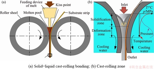
Fig. 1 Schematic of twin-roll casting process
As shown in Fig. 1, the solid-liquid cast- rolling bonding is based on the traditional twin-roll casting. The cast-rolling zone is divided into the liquid (solidification) and solid (deformation) zones. Solid metal is the substrate strip, and molten metal is the cladding. They simultaneously are fed into the rollers at the same time. Then, the cladding bonds with the substrate strip after rapid solidification [14,15]. According to the temperature features of the cast-rolling zone, all zones below the KP are deformation zones. The total unit rolling force is the sum of the force of the substrate strip and cladding.
2.1 Basic assumptions
(1) Due to the low deformation resistance in the solidification zone at high temperature, it is considered to be the hot-rolled bonding deformation of the solid-solid strip below the KP.
(2) Slip friction is considered in the deformation zone, and the cladding and substrate strip are bonded at the outlet.
(3) It is assumed that the plastic deformation of bimetal solid-liquid cast-rolling bonding is a plane deformation, which satisfies Mises yield criterion under the condition of plane plastic deformation.
(4) The deformation of the substrate strip makes itself thin.
(5) The influence of molten pool level fluctuation on the temperature of the cast-rolling zone is ignored.
2.2 Structure and geometric parameters of cast- rolling zone
Figure 2 presents a schematic of the cast- rolling zone. The geometric relationships are expressed as follows:
 (1)
(1)
 (2)
(2)
 (3)
(3)
 (4)
(4)
 (5)
(5)
In the formulas, L=L0+LK and SK=S0+��S. The rolling start condition is tan �¡ܦ�3, and
 (6)
(6)
where LK is the KP height, ��3 is the friction factor of roller-substrate, �� is the bite angle, �� is the neutral angle, and l is the contact arc length. According to the formula, the bite is more favorable when the roll radius is larger and the KP height is lower. After transforming the formula, the maximum height of the KP is LK�ܦ�3[R-(��S/2)+H0] to ensure the stable start of rolling.
3 Derivation of unit pressure formula
3.1 Unit pressure in forward slip zone and backward slip zone of cladding
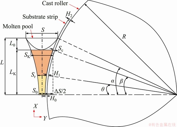
Fig. 2 Geometric diagram of cast-rolling zone
A micro unit is taken from the deformation zone of cladding, and the force situation is shown in Fig. 3. List the force balance equation in the x direction, and get Eq. (7):

 (7)
(7)
 (8)
(8)
Equation (8) is substituted into Eq. (7), and the higher-order terms are removed to obtain the following equation:
 (9)
(9)
where the backward slip zone is �� �� and the forward slip zone is ��
 ��.
��.
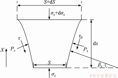
Fig. 3 Stress analysis of micro unit in cladding
The yield criterion is introduced: Px-��x=K, and K is the deformation resistance of cladding, which is called plane deformation resistance. The plane deformation resistances of the forward and the backward slip zones are different, and decrease with the increasing temperature.
The friction factors of different strip surfaces are different, the friction factors of roller-cladding and cladding-substrate strip are ��1 and ��2, respectively. The frictional force can be described as ��=Px��1 and ��0=Px��2. To simplify the calculation, the corresponding contact arc is replaced by a string: dx=(LKds)/��S. By introducing dx into Eq. (9), is derived.
Let  , and then the following is obtained after simplification:
 (10)
(10)
(1) Calculation of unit pressure of micro unit in the forward slip zone
According to the geometric structure, the boundary conditions are S=S0 and Px=K. By solving the first-order linear differential equation of Eq. (10), the unknown parameters are obtained and the unit pressure in the forward slip zone is expressed as
 (11)
(11)
(2) Calculation of unit pressure of micro unit in the backward slip zone
Similarly, by solving the first-order linear differential equation of Eq. (10) when S=SK and Px=-K, the unit pressure in the backward slip zone is obtained as
 (12)
(12)
The upper and lower limits of the integral in the backward slip zone are [Sr, SK], and the upper and lower limits of the integral in the forward slip zone are [S0, Sr]. Sr is the neutral layer thickness of the cladding.
3.2 Unit pressure in forward slip zone and backward slip zone of substrate strip
Analogously, a micro unit is taken from the substrate strip, and the stress analysis is shown in Fig. 4.
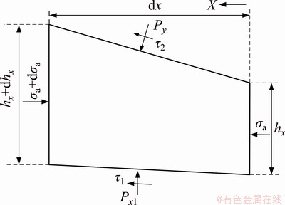
Fig. 4 Stress analysis of micro unit in substrate strip
The relationship between friction and pressure is as follows: ��1=��0, Px1=Px, ��1=��2Px and ��2=��3Py. The yield criterion is introduced: (Py-Px)-��a=K1, and K1 is the plane deformation resistance of the substrate strip. List the force balance equation in the X direction, and the equation can be expressed as
 (13)
(13)
Let  .
.
(1) Calculation of unit pressure of micro unit in the forward slip zone
By solving the first-order linear differential equation of Eq. (13) when hx=H0 and Py=K1, the unit pressure in the forward slip zone is obtained.
Let  , and
, and 
 .
.
The unit pressure of the forward slip zone is
 (14)
(14)
(2) Calculation of unit pressure of micro unit in the backward slip zone
Similarly, by solving the first-order linear differential equation of Eq. (13) when hx=H2 and Py=-K1, the unit pressure in the backward slip zone is obtained.
Let  and
and 
 .
.
The unit pressure of the forward slip zone is
 (15)
(15)
The upper and lower limits of the integral in the backward slip zone are [H1, H2], and the upper and lower limits of the integral in the forward slip zone are [H0, H1]. H1 is the neutral layer thickness of the substrate strip.
3.3 Total rolling force
The unit pressure of the micro unit in the forward and backward slip zones of the cladding and substrate strip is integrated in the thickness direction. Then, the sum is equal to the total unit pressure:
 (16)
(16)
The cast-rolling rolling force is equal to the product of the total unit pressure, the width B of the clad strip, and contact arc length l:
F=P��B��l (17)
4 Calculation example
Most of the parameters in the formulas can be obtained through geometric relations, except for the KP height LK and the deformation resistances K, K1 of the strips. The parameters are related to the temperature distribution in the cast-rolling zone, which is mainly affected by the working conditions. In this example, the Fluent software is adopted to carry out a thermal-flow coupled numerical simulation under the steady-state condition and the rolling force is calculated corresponding to the different KP heights based on the Cu/Al clad strips. Furthermore, the effects of the different cast-rolling speeds, thicknesses and materials of the substrate strip on the temperature of the cladding strip are compared.
4.1 Thermal-flow coupled numerical simulation
According to the twin-roll casting experiment, a steady-state thermal-flow coupled model of cast-rolling zone is established based on the Fluent software, including four calculation fields: left roller, aluminum molten pool, copper substrate strip and right roller. Figure 5 shows the schematic of the grid model. In order to improve the calculation accuracy and the convergence speed, the mesh of the molten pool and the calculated domains in the substrate strip are densified, and the coupling boundary mesh nodes among the calculated domains correspond to each other. The thermal conductivity of the air gap among the calculated domains is set to be 0.02 W/(m��K) and convection heat transfer coefficient between the roller and cooling water is set to be 8000 W/(m2��K) [16,17]. The remaining main simulation parameters are given in Table 1.
Figure 6 shows the simulation results of the Cu/Al clad strip fabricated by solid-liquid cast- rolling bonding when V=3.6 m/min, TCasting=700 ��C, HCu=0.5 mm, and TCu=27 ��C. The temperatures of the copper strip and the rollers increase after heat absorption, and the temperature of the molten aluminum gradually decreases in the cast-rolling direction, and cools from liquid to solid. When the temperature of a certain zone exceeds the liquidus temperature, this zone is called the liquid phase zone, which has nearly no rolling force. In contrast, when the temperature of a certain zone decreases to the liquidus temperature, the molten aluminum solidifies into a solid state, which is called the solid phase zone. As shown in Fig. 6, LK is the length of the rolling zone. Furthermore, due to the asymmetry of heat transfer caused by the geometric asymmetry of the cast-rolling zone, the temperature of the left roller is higher than that of the right roller, and the KP is biased toward the left roller.
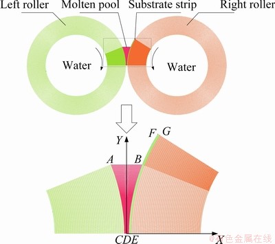
Fig. 5 Schematic diagram of mesh
Table 1 Simulation parameters
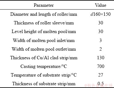
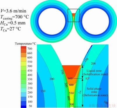
Fig. 6 Temperature field of Cu/Al solid-liquid cast-rolling composite forming process
In order to figure out the influence of various working conditions on the KP position and the temperature, Fig. 7 shows the distribution of the temperature field in the cast-rolling zone of Cu/Al and Ti/Al at different thicknesses and rolling speeds when TCasting=700 ��C and TCu=TTi=27 ��C. It is indicated that the KP height increases with increasing of the thickness of substrate strip, and decreases with increasing of the cast-rolling speed. Similarly, the temperature of outlet and neutral layer decreases with increasing strip thickness and increases with increasing cast-rolling speed. The KP migration becomes more significant and the vortex number in the molten pool increases when the rolling speed increases and the substrate becomes thin. In addition, Fig. 8 explains that, the KP height of the Cu/Al clad strip is higher than that of the Ti/Al clad strip under the same conditions.
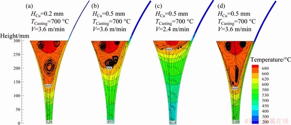
Fig. 7 Thermal-flow coupled simulation under different cast-rolling conditions
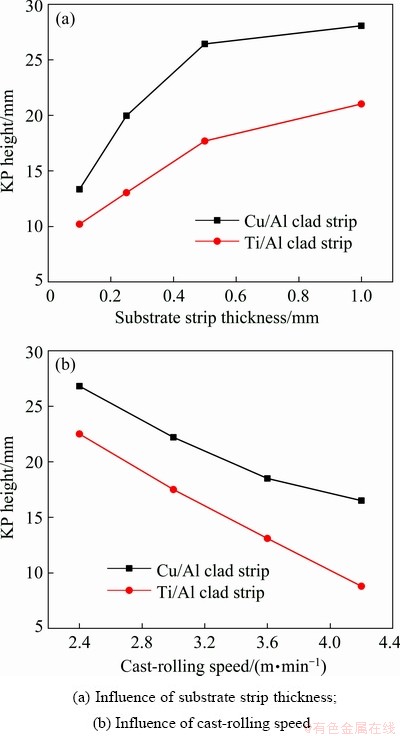
Fig. 8 Influence of substrate strip thickness and cast-rolling speed on KP height when TCasting=700 ��C and TTi=TCu=27 ��C
Therefore, the larger the substrate thickness is, the greater the heat absorption will be, and the decrease in rolling speed and increase in cooling time of the molten metal will increase the KP height. In addition, a substrate strip with a high thermal conductivity is conducive to heat transfer and will result in a small thermal resistance between the roller sleeve and the liquid metal, increasing the KP height.
4.2 Example of rolling force calculation
Taking the Cu/Al clad strip as the object, the rolling force at different rolling speeds were calculated. The calculation steps of cast-rolling force can be summarized as follows:
(1) According to the technological parameters, the geometric relationships of cast-rolling zone are obtained, and the friction factors ��1, ��2, and ��3 are determined. The specific values of friction coefficient ��2 and ��3 are obtained by consulting the mechanical design manual. Given that aluminum is easy to oxidize, the friction factor ��1 can be obtained as described in Ref. [18]. In this case, ��1=0.29, ��2=0.27, and ��3=0.19.
(2) The outlet thicknesses of the cladding and substrate strip are obtained by experiments. The KP heights LK and the deformation resistances K, K1 of the metals are obtained by the thermal-flow coupled simulation.
(3) Finally, the total rolling force is calculated by integrating and summing the unit rolling force of the cladding and substrate strip.
There are forward and backward slip zones in the metal rolling deformation process. The direction of friction in the forward slip zone is opposite the rolling direction, hindering the rolling process, but having a positive effect on stable rolling. The direction of friction in the backward slip zone is the same as the rolling direction, and the roller bites the metal into the roller gap through the friction in the backward slip zone [19]. To prevent the molten aluminum from sticking to the roller after solidification, graphite is applied on the roller surface before rolling, reducing the friction coefficient between the metal and roller. When other conditions are constant, the smaller the friction coefficient is, the smaller the proportion of the forward slip zone in the deformation zone is. The experiment revealed that only a backward slip zone existed due to the thin copper strip and the small amount of deformation.
According to the study of the high-temperature rheological behavior of industrial pure aluminum by ZHAN [20], the plane deformation resistance of pure aluminum decreases with increasing the temperature. So does the high temperature deformation behavior of the pure copper [21]. With the same roller structure, the simulation results at different rolling speeds are used as references during the calculation to determine the deformation resistance of the cladding and substrate strip. According to Fig. 9(a), the plane deformation resistance of molten aluminum in the backward slip zone is determined by the average temperature of the inlet and neutral layer, and the plane deformation resistance of the forward slip zone is determined by the average temperature of the neutral layer and outlet. Specific values can be obtained from Ref. [20]. Given the small deformation of the copper strip, plane deformation resistance K1 is determined as a constant, approximately taking K1=100 MPa when TCu= 500 ��C.
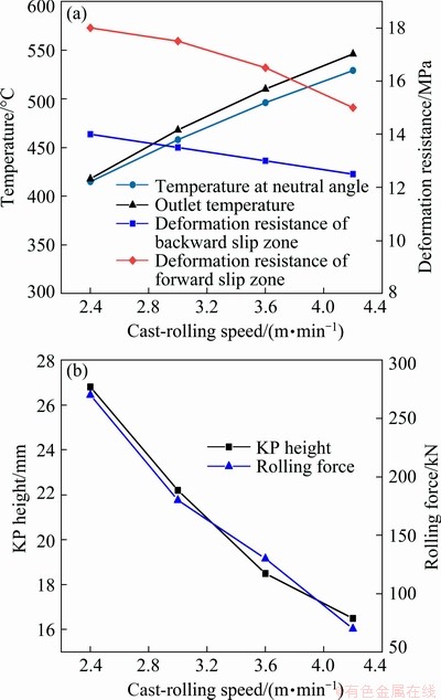
Fig. 9 Temperature and deformation resistance (a), and KP height and rolling force (b) of aluminum cladding
The upper and lower limits of the rolling force integral calculation can be obtained by combining the simulation results and the geometric relationship, and the rolling force can be calculated by substituting each parameter into the formula. Figure 9(b) shows the rolling force calculation results at different rolling speeds when TCasting= 700 ��C, HCu=0.5 mm, and S0=2 mm. The results indicate that, the KP height and the rolling force decrease significantly when the rolling speed increases.
5 Rolling force test
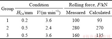
To verify the accuracy of the model for calculating the cast-rolling force and explore the influence of the rolling speed, thickness and material of the substrate strip on the rolling force, DHDAS Data Acquisition System was used to collect the rolling force data. According to the parameters in Fig. 7, the cast-rolling force test was carried out, and the results are given in Table 2. The experimental results are similar to the calculated values. Compared with the calculated value of the rolling force in Fig. 9(b), the measured rolling force was 280 kN and the calculated value was 270 kN when HCu=0.5 mm and V=2.4 m/min. When HCu= 0.5 mm and V=3.6 m/min, the measured rolling force was 160 kN and the calculated value was 135 kN. The fluctuation of the liquid level and the collection of data had a great influence on the experimental results. Contrastive analysis indicates that the calculated values are basically consistent with the measured values, and the calculation accuracy of the model satisfies the requirements. In addition, the measured rolling force was 130 kN when HTi=0.5 mm and V=3.6 m/min. Obviously, the substrate strip had a great influence on the rolling force under the same parameters.
Table 2 Rolling force measurement results
As shown in Fig. 10, the ratios of the rolling force in the backward slip zone of the copper strip, the forward slip zone and the backward slip zone of the aluminum strip were calculated. The thicknesses of the copper strip and the aluminum cladding were measured. The copper strip thinning was 0.14 mm when HCu=0.5 mm and V=2.4 m/min. The copper strip thinning is 0.06 mm when HCu=0.5 mm and V=3.6 m/min. The outlet thickness of aluminum cladding was approximately 2 mm. Figure 10 shows that the backward slip zone of aluminum cladding was the main contributor to the total rolling force. More remarkably, the contribution of the copper strip to the rolling force increased to 21.4% when the rolling speed was 2.4 m/min. Figure 7 shows that a high KP results in increased thickness ratio between the aluminum cladding and the copper strip. Thus, the deformation of the copper strip and the contribution to the rolling force increase.
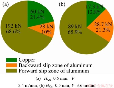
Fig. 10 Rolling force ratios of copper strip and aluminum cladding when TCasting=700 ��C
Thus, during the process of solid-liquid cast- rolling bonding, the rolling force is proportional to the KP height. The main rolling force is provided by the backward slip zone of the molten cladding. Hence, the KP is the ��intersection point�� of the rolling speed, thickness, and material of the substrate strip. Experiments show that the assumptions of the calculation model are correct, but the accuracy of numerical simulation and parameter values must be improved further.
Furthermore, in the industrial production process, predicting and controlling the KP height through the reasonable setting of working conditions are beneficial to the strip quality and the production efficiency. However, it is insufficient that the thinning rule of the substrate strip under various working conditions is unknown. In the next step, a series of simulations and experiments are implemented to obtain the true temperature of the cast-rolling zone and the thinning rule of the substrate strip under different working conditions. And then, the KP height function can be expressed as
 (18)
(18)
This work provides a new idea for calculating the cast-rolling force that is beneficial for achieving intelligent control of the cast-rolling process and has a guiding significance in actual industrial production.
6 Conclusions
(1) According to the temperature distribution characteristics of the cast-rolling zone, the deformation zone is divided into the forward and backward slip zones below the KP. On the basis of this assumption, a model for calculating the cast- rolling force is proposed.
(2) A thermal-flow coupled numerical simulation is established by using the Fluent software. The KP height and the temperature field are obtained by numerical simulation. Furthermore, the effects of rolling speed, substrate strip thickness and material on the temperature field in the cast-rolling zone are analyzed.
(3) The accuracy of the rolling force calculation model is verified by a rolling force measurement experiment. The results show that the rolling force increases with increasing the substrate strip thickness, decreases with increasing the rolling speed, and increases with increasing the thermal conductivity of substrate strip. The reason is that the working conditions change the KP height and the deformation resistance of the bimetal. Furthermore, the molten cladding backward slip zone accounts for the largest proportion to the total rolling force.
Acknowledgments
The authors are grateful for the financial supports from the National Natural Science Foundation of China (51974278) and the Distinguished Young Fund of Natural Science Foundation of Hebei Province, China (E2018203446).
References
[1] JI Ce, HUANG Hua-gui. A review of the twin-roll casting process for complex section products [J]. ISIJ International, 2020, 60(11): 1-11.
[2] LEE D H, KIM J S, SONG H, LEE S. Tensile property improvement in Ti/Al clad sheets fabricated by twin-roll casting and annealing [J]. Metals and Materials International, 2017, 23(4): 805-812.
[3] CHEN G, LI J T, YU H L, SU L H, XU G M, PAN J S, YOU T, ZHANG G, SUN K M, HE L Z. Investigation on bonding strength of steel/aluminum clad sheet processed by horizontal twin-roll casting, annealing and cold rolling [J]. Materials & Design, 2016, 112: 263-274.
[4] LI Si, WANG Zhi-gang, Guo Yu-fei. A novel analytical model for prediction of rolling force in hot strip rolling based on tangent velocity field and MY criterion [J]. Journal of Manufacturing Processes, 2019, 47: 202-210.
[5] ZHANG Shu-hong, ZHANG Dai-ming, LI Shi-yun, CHEN Ke-qiao, LI Jian-yun. Theoretical analysis of rolling-force for bimetal composite thin plate [J]. Journal of Kunming University of Science and Technology, 2001, 26(5): 1-3. (in Chinese)
[6] CAO Guang-ming, LIU Zhen-yu, WU Di, LIU Xiang-hua, WANG Guo-dong. Study on rolling force calculation for twin-roll strip casting [J]. Iron and Steel, 2008, 43(8): 49-53. (in Chinese)
[7] SUN Bin-yu, LIANG Ai-sheng, WANG Hai-wen. A computation of casting-rolling force for the twin-roll aluminum strip caster [J]. Heavy Machinery, 1991, 25(2): 43-46. (in Chinese)
[8] HUANG Hua-gui, JI Ce, DU Feng-shan. Research on cast-rolling force calculation model in solid-liquid cast-rolling bonding (SLCRB) process of bimetallic clad pipe [J]. Journal of Mechanical Engineering, 2017, 53(10): 10-17. (in Chinese)
[9] HUANG H G, CHEN P, JI C. Solid-liquid cast-rolling bonding (SLCRB) and annealing of Ti/Al cladding strip [J]. Materials & Design, 2017, 118: 233-244.
[10] HUANG Hua-gui, DONG Yi-kang, YAN Meng, DU Feng-shan. Evolution of bonding interface in solid�Cliquid cast-rolling bonding of Cu/Al clad strip [J]. The Chinese Journal of Nonferrous Metals, 2017, 27(5): 1019-1025. (in Chinese)
[11] GRYDIN O, STOLBCHENKO M, SCHAPER M. Deformation zone length and plastic strain in twin-roll casting of strips of Al-Mg-Si alloy [J]. JOM, 2017, 69(12): 2648-2652.
[12] STOLBCHENKO M, GRYDIN O, SAMSONENKO A, KHVIST V, SCHAPER M. Numerical analysis of the twin-roll casting of thin aluminum-steel clad strips [J]. Forschung Im Ingenieurwesen, 2014, 78(3-4): 121-130.
[13] LEE Y S, KIM H W, CHO J H, CHUN S H. Coupled thermal-fluid-mechanics analysis of twin roll casting of A7075 aluminum alloy [J]. Metals & Materials International, 2017, 23(5): 923-929.
[14] GRYDIN O, GERSTEIN G, FLORIAN N, SCHAPER M, DANCHENKO V. Twin-roll casting of aluminum-steel clad strips [J]. Journal of Manufacturing Processes, 2013, 15(4): 501-507.
[15] CHENG Gang, LI Jin-tao, XU Guang-ming. Bonding process and interfacial reaction in horizontal twin-roll casting of steel/aluminum clad sheet [J]. Journal of Materials Processing Technology, 2017, 246: 1-12.
[16] JI Ce, HUANG Hua-gui, ZHANG Jun-peng, ZHAO Ri-dong. Influence of the substrate strip on the asymmetric heat transfer of twin-roll casting for fabricating bimetallic clad strips [J]. Applied Thermal Engineering, 2019: 113818.
[17] PARK J J. Finite-element analysis of severe plastic deformation in differential-speed rolling [J]. Computational Materials Science, 2015, 100: 61-66.
[18] WANG Wei-wei. The study on the temperature calculation model of 5052 A1 plate in hot continuous rolling [D]. Changsha: Central South University, 2012: 30-33. (in Chinese)
[19] CHEN Shui-xuan, LI Wei-gang, LIU Xiang-hua. Calculation of rolling pressure distribution and force based on improved Karman equation for hot strip mill [J]. International Journal of Mechanical Sciences, 2014, 89: 256�C263.
[20] ZHAN Li-hua. Experimental study on high temperature rheological behavior of commercial pure aluminum [J]. Hot Working Technology, 2006, 35(8): 7-11. (in Chinese)
[21] ZHAO Rui-long, LIU Yong, TIAN Bao-hong, ZHANG Xiao-wei, ZHANG Yi. High temperature deformation behavior of pure copper [J]. Heat Treatment of Metals, 2011, 36(8): 17-20. (in Chinese).
˫�������ϰ��-Һ��������������ģ��
�ſ���1,2���ƻ���1,2�����ն�1,2���� ��1,2���� ��1,2
1. ��ɽ��ѧ �����������װ�������չ��̼����о����ģ��ػʵ� 066004��
2. ��ɽ��ѧ ��е����ѧԺ���ػʵ� 066004
ժ Ҫ�����ڴ�ͳ˫���������գ����˫�������ϰ��-Һ��������������ģ�͡��������̵�(KP)����Ϊ��-�̸�����������Һ�����ı��ο������������Ƶ����㹫ʽ��ͨ��������ά��-�����ģ��Ϊģ���еIJ����ṩȡֵ���ݣ����㲻ͬ�����ٶ����Ʊ�Cu/Al���ϰ����������ͬʱ��ͨ��ʵ����֤��ģ�͵Ŀɿ��ԣ�����������ٶȡ������ȺͲ��϶���������Ӱ����ɡ�����������������������ٶȵ����Ӷ���С��������Ⱥ͵���ϵ�������Ӷ�������������KP�߶���أ���ˣ��ƶ������Ĺ��ղ�������KP�߶ȶ��������ε��ȶ��Ծ�����Ҫ���塣
�ؼ��ʣ�˫�������ϰ壻��-Һ�������ϣ�����������ģ�ͣ����̵㣻��-�����ģ��
(Edited by Bing YANG)
Corresponding author: Hua-gui HUANG; E-mail: hhg@ysu.edu.cn
DOI: 10.1016/S1003-6326(21)65524-3
1003-6326/ 2021 The Nonferrous Metals Society of China. Published by Elsevier Ltd & Science Press
Abstract: Based on twin-roll casting, a cast-rolling force model was proposed to predict the rolling force in the bimetal solid-liquid cast-rolling bonding (SLCRB) process. The solid-liquid bonding zone was assumed to be below the kiss point (KP). The deformation resistance of the liquid zone was ignored. Then, the calculation model was derived. A 2D thermal-flow coupled simulation was established to provide a basis for the parameters in the model, and then the rolling forces of the Cu/Al clad strip at different rolling speeds were calculated. Meanwhile, through measurement experiments, the accuracy of the model was verified. The influence of the rolling speed, the substrate strip thickness, and the material on the rolling force was obtained. The results indicate that the rolling force decreases with the increase of the rolling speed and increases with the increase of the thickness and thermal conductivity of the substrate strip. The rolling force is closely related to the KP height. Therefore, the formulation of reasonable process parameters to control the KP height is of great significance to the stability of cast-rolling forming.
