退火对激光熔化沉积制备γ-TiAl合金显微组织和力学性能的影响
来源期刊:中国有色金属学报(英文版)2020年第4期
论文作者:刘占起 马瑞鑫 徐国建 王文博 苏允海
文章页码:917 - 927
关键词:激光熔化沉积;退火;TiAl合金;显微组织演变;力学性能
Key words:laser melting deposition; annealing; TiAl alloy; microstructure evolution; mechanical properties
摘 要:研究激光熔化沉积制备γ-TiAl合金沉积态和不同温度退火态样品的显微组织演变和力学性能。结果表明,沉积态试样的显微组织由细小α2(Ti3Al)+γ片层构成。随着退火温度的升高,块状γm(TiAl)相逐渐由单一γ相→γ相 + 针状α2相→γ相 + 片层状α2+γ方向转变。与沉积态γ-TiAl合金的力学性能(抗拉强度469 MPa、伸长率1.1%)相比,经1260 °C、30 min、FC退火处理后,试样的室温抗拉强度为543.4 MPa,伸长率为3.7%,其力学性能得到显著提高。
Abstract: The microstructure evolution and mechanical properties of the as-deposited γ-TiAl-based alloy specimen fabricated via laser melting deposition and as-annealed specimens at different temperatures were investigated. The results show that the microstructure of as-deposited specimen is composed of fine α2(Ti3Al)+γ lamellae. With the increase of annealing temperature, the bulk γm (TiAl) phase gradually changes from single γ phase to γ phase + acicular α2 phase, finally small γ phase + lamellar α2+γ phase. Compared with the mechanical properties of as-deposited γ-TiAl alloy (tensile strength 469 MPa, elongation 1.1%), after annealing at 1260 °C for 30 min followed by furnace cooling (FC), the room-temperature tensile strength of the specimen is 543.4 MPa and the elongation is 3.7%, which are obviously improved.
Trans. Nonferrous Met. Soc. China 30(2020) 917-927
Zhan-qi LIU, Rui-xin MA, Guo-jian XU, Wen-bo WANG, Yun-hai SU
School of Materials Science and Engineering, Shenyang University of Technology, Shenyang 110870, China
Received 13 May 2019; accepted 18 February 2020
Abstract: The microstructure evolution and mechanical properties of the as-deposited γ-TiAl-based alloy specimen fabricated via laser melting deposition and as-annealed specimens at different temperatures were investigated. The results show that the microstructure of as-deposited specimen is composed of fine α2(Ti3Al)+γ lamellae. With the increase of annealing temperature, the bulk γm (TiAl) phase gradually changes from single γ phase to γ phase + acicular α2 phase, finally small γ phase + lamellar α2+γ phase. Compared with the mechanical properties of as-deposited γ-TiAl alloy (tensile strength 469 MPa, elongation 1.1%), after annealing at 1260 °C for 30 min followed by furnace cooling (FC), the room-temperature tensile strength of the specimen is 543.4 MPa and the elongation is 3.7%, which are obviously improved.
Key words: laser melting deposition; annealing; TiAl alloy; microstructure evolution; mechanical properties
1 Introduction
Titanium aluminium (TiAl) alloy has high melting point (greater than 1450 °C), low density (4 g/cm3), high elastic modulus (160-180 GPa) and high creep strength (up to 900 °C, 150-300 MPa). In recent years, TiAl alloy has gradually replaced titanium alloy, nickel-based superalloy and heat- resistant steel. It has great potential in aerospace and vehicle engine manufacturing [1-5]. The room temperature plasticity, ductility and brittleness of TiAl alloy are poor, so it is difficult to be machined by conventional manufacturing processes (such as forging, rolling and welding), which limits the wide application of TiAl alloy [6]. The existing forming methods of TiAl alloy are mainly near-net forming, including powder metallurgy, precision casting, directional solidification and so on. Among them, the laser coaxial powder feeding manufacturing technology has remarkable advantages in the near-net forming of TiAl alloy. In addition, the microstructure and properties of the alloy can be effectively controlled by optimizing the process parameters under the action of laser beam, and the molding density can reach more than 98.5% [7].
TiAl-based compounds have been extensively studied. However, there are few studies on annealing treatments of Ti-48Al-2Cr-2Nb alloy. For example, JAN and CAROLIN [8] prepared Ti-48Al-2Cr-2Nb alloy, and obtained a significantly refined microstructure by only adjusting different beam parameters. QU et al [9] prepared thin walled specimens of Ti-47Al-2.5V- 1Cr alloy with directional columnar crystals by laser melting deposition (LMD) technique, and analyzed the microstructure and tensile properties at room temperature. MA et al [10] found that the post-heat treatment has a significant effect on the microstructure of the deposited specimens, and through the controlled post-heat treatment, the microstructure of ultrafine lamellar was obtained. RITTINGHAUS et al [11] applied different kinds of heat treatment systems for laser melting deposition of Ti-43.5Al-4Nb-1Mo-0.1B (TiAl TNM) alloy, and analyzed the effect of different heat treatment systems on the microstructure change, but did not test the mechanical properties. ZHANG et al [12] welded Ti2AlNb alloy by laser powder feeding technology, and then heat-treated the welded specimens, and analyzed the effect of heat treatment on microstructure and mechanical properties. Compared with Ti3Al-based alloy and Ti2AlNb- based alloy, γ-TiAl alloy has lower density, better high-temperature strength and better oxidation resistance [13,14]. To ensure this research having a broad impact on LMD technology for TiAl-based alloys, the Ti-48Al-2Cr-2Nb alloy was thus selected for an annealing study.
The purpose of this study is to illustrate the effects of annealing temperature on mechanical properties of the Ti-48Al-2Cr-2Nb alloy fabricated using LMD. The microstructure evolution, phase composition, texture distribution and mechanical properties of specimens at different annealing temperatures were studied in detail, which can provide a theoretical basis for practical applications of aero-engine disks.
2 Experimental
The Ti-48Al-2Cr-2Nb spherical powder material used in this experiment was produced by Beijing AMC Powder Metallurgical Technology Co., Ltd., China. The particle size of the powder was 53-150 μm, and its chemical compositions (wt. %) were Al 32.5, Cr 2.64, Nb 4.62, O 0.06, N 0.005 and Ti balanced. Before the test, the powder was placed in a vacuum drying box and dried at 200 °C for 1 h; the substrate was made of TC4 titanium alloy with dimensions of 100 mm × 100 mm × 10 mm. Before the test, the substrate surface was polished by a grinder to remove the oxide film and surface defects and expose the luster of metal. Finally, the substrate surface was wiped with acetone and alcohol.
LDM equipment, model LDM8060, was manufactured and supplied by Nanjing Zhongke Yuchen Laser Technology Co., Ltd., China. The laser processing set-up was composed of LDF-4000 semiconductor laser equipment, four-way powder feeding print head, air-borne powder feeder, water cooler, three-axis numerical control worktable and inert gas chamber. 99.99% Ar protective gas was used inside an inert gas compartment, and the water and oxygen contents of inert gas compartments were less than 50×10-6. The experimental parameters of LMD were as follows: laser power 1400 W, scanning velocity 9 mm/s, powder feeding velocity 5.67 g/min, powder feeding gas (Ar) flow rate 8 L/min, laser spot diameter 3 mm. The defocusing amount was 0 mm and the distance from the laser head to the workpiece was 15 mm. Using the preheating device, the substrate was heated to 400 °C, then heating was stopped and printing started. Under the above parameters, the thickness of the deposited layers was about 0.4 mm, and a defect-free thin-walled specimen with dimensions of 40 mm × 5 mm × 53 mm was successfully prepared. The physical photograph of as-deposited specimen is shown in Fig. 1. γ-TiAl alloy specimens were annealed at different temperatures. The annealing temperature range was in α+γ two-phase region. Its specific annealing treatment is shown in Fig. 2.
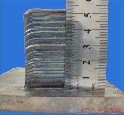
Fig. 1 Physical photograph of as-deposited specimen
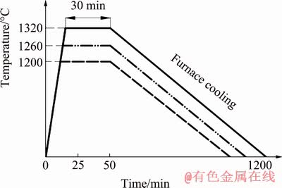
Fig. 2 Schematic diagram of annealing treatment
The metallographic specimens and room- temperature tensile specimens were wire-cut along the Z direction. The dimensions of the metallographic specimens were 10 mm × 10 mm × 5 mm. They were ground, polished and corroded. Kroll solution was used as corrosion reagent, its volume ratio was V(HF):V(HNO3):V(H2O)=2:3:10, and corrosion time was 5 s. ZX-10 Zeiss optical microscope (OM) and Hitachi S-3400N scanning electron microscope (SEM) were used to analyze the microstructure and fracture morphology of the specimens. The phase composition of the specimens was studied by an X-7000 X-ray diffraction analyzer, using a scanning rate of 8 (°)/min and a scan range (2θ) of 20°-90°. The phase distribution and texture distribution of the specimens were studied by electron backscattered diffraction (EBSD), and the polar map processing of the EBSD was obtained by Channel-5 software. The parameters of EBSD test were as follows: the step size 0.7 μm and pattern indexing rate 23 point/s. The room-temperature tensile test (loading rate 0.5 mm/min) was carried out by a WDW-100 universal testing machine. The sizes of the tensile specimens are shown in Fig. 3. The Vickers hardness distribution (loading force of 200 g and duration of 10 s) was measured by an HVS-5 Vickers hardness tester. The specimens were annealed by a ZSL 1600X heat treatment furnace.
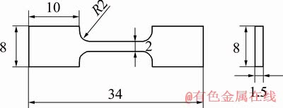
Fig. 3 Schematic diagram of tensile specimen size (unit: mm)
3 Results and discussion
3.1 Morphology
Figure 4 shows morphologies of cross-sections for the as-deposited specimen. Figures 4(a, c, e) show macrostructures of the top, middle and bottom regions of the as-deposited specimen, respectively. Figures 4(b, d, f) show local magnifications corresponding to Figs. 4(a, c, e), respectively. From Figs. 4(c) and (d), it can be seen that the macrostructure of the as-deposited specimen is basically composed of columnar crystals, and the microstructure of columnar crystals is composed of fine lamellar structures, which have been reported in detail in previous research [15]. From Figs. 4(a) and (b), it can be seen that at the top of the as-deposited specimen a small amount of equiaxed crystals are formed, and the microstructure in the equiaxed grains is also composed of lamellar structure. Figures 4(e) and (f) show the bottom structure of the as-deposited specimen, which is composed of a bulk α2 phase due to the influence of the TC4 substrate material [16].
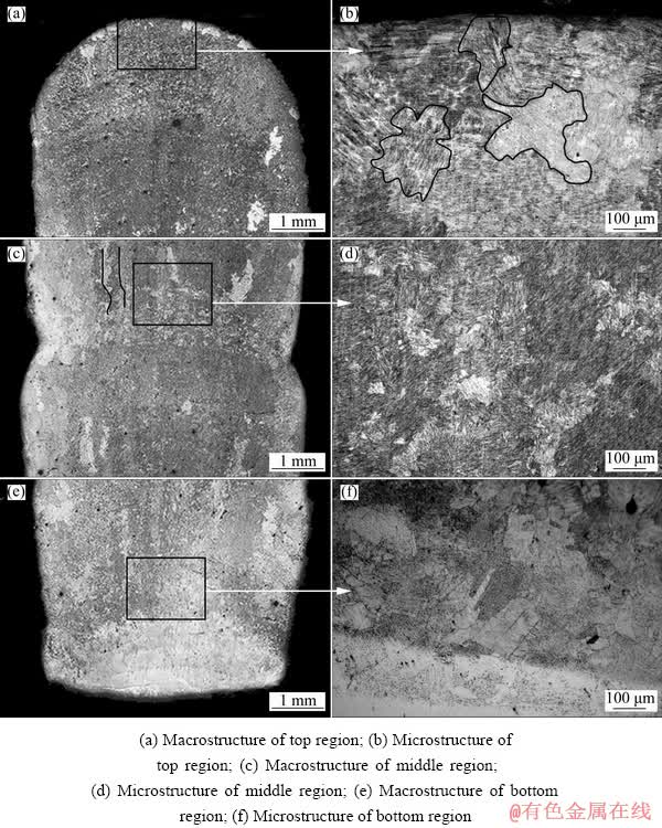
Fig. 4 Morphologies of cross sections of as-deposited specimen
The TiAl binary phase diagram is shown in Fig. 5. From Fig. 5, it can be seen that when the annealing temperatures are 1320, 1260 and 1200 °C, respectively, different phases will be achieved. The effect of annealing temperature on microstructures of different specimens is shown in Fig. 6. From the microstructures in Fig. 6, it can be seen that the microstructure at annealing temperature of 1320 °C is nearly lamellar structure (NL); the microstructure at annealing temperature of 1260 °C is duplex microstructure (DP); the microstructure at annealing temperature of 1200 °C is near γ structure (NG).
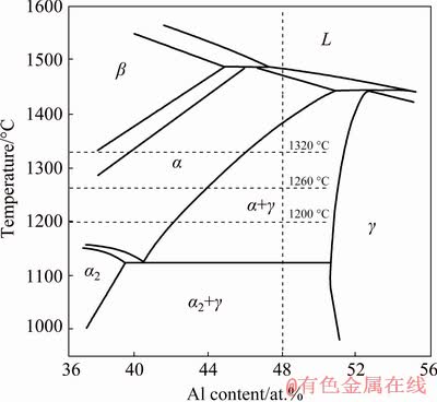
Fig. 5 Ti-Al binary phase diagram
From Fig. 6(a), it can be seen that the microstructure of the as-deposited specimen is composed of fine α2+γ lamellar structures. Figure 6(b) shows that the microstructure annealed at 1200 °C is composed of a small amount of bulk γm phase and a large number of α2+γ lamellar structures. During the furnace cooling, the α phase transforms to the α2+γ lamellar structures and the remaining γ phase grows into the bulk γm phase.
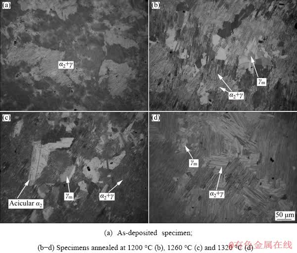
Fig. 6 Effect of annealing temperature on microstructures of different specimens
With the annealing temperature decreasing, the volume fraction of the bulk γm phase increases. As can be seen from Fig. 6(c), the microstructure annealed at 1260 °C is still composed of massive γm phase and α2+γ lamellar structure, but compared with Fig. 6(b), the content of the bulk γm phase increases obviously and acicular α2 phase precipitates form it. The results show that the remaining γ phase grows continuously with the increase of annealing temperature, and acicular α2 phase precipitates from the bulk γm phase in the cooling process. As can be seen from Fig. 6(d), the microstructure annealed at 1320 °C consists of a small bulk γm phase distributed at the grain boundary and a large number of α2+γ lamellar structures, but the thickness of the α2+γ lamellar is obviously increased compared with that in Fig. 6(c). This is due to the higher annealing temperature, the weakening of remaining γ phase hindrance and the growth of α phase, which eventually result in the increase of α2+γ lamellar spacing.
3.2 Phase composition and distribution
Figure 7 shows the XRD patterns of the as-deposited specimen and specimens annealed at different temperatures. From the results of XRD analysis, the microstructure of the as-deposited
specimen is composed of α2 and γ phases. The diffraction peak of γ (111) has the highest intensity for the as-deposited specimen. The γ (202) diffraction peaks of the specimen annealed at 1200 °C for 30 min and at 1260 °C for 30 min have higher intensity. However, compared with other three groups of diffraction peaks, the intensity of diffraction peak at 1320 °C for 30 min is the lowest.
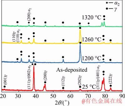
Fig. 7 XRD patterns of as-deposited specimen and specimens annealed at different temperatures
Figure 8 shows phase distribution maps of as-deposited specimen and the specimens annealed at different temperatures. The blue represents γ phase and red represents α2 phase. The contents and distribution of α2 phase are shown in Figs. 8(a-d). The results of EBSD analysis show that the volume fractions of α2 phase in the as-deposited specimen and specimens annealed at 1200, 1260 and 1320 °C are 0.3%, 1.6%, 1.4% and 1.9%, respectively. The volume fractions of γ phase in the as-deposited specimen and specimens annealed at 1200, 1260 and 1320 °C are 99.7%, 98.4%, 98.6% and 98.1%, respectively. The experimental results show that the content of α2 phase is the highest when the annealing temperature is 1320 °C. The main reason is that more α-Ti solid solutions are precipitated at annealing temperature of 1320 °C, and more α2 phases are formed in the subsequent eutectoid reaction (α-Ti→α2 (Ti3Al)+γ (TiAl)).
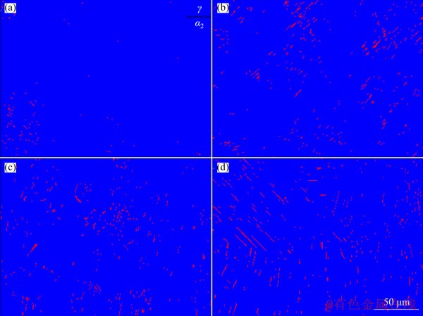
Fig. 8 Phase distribution maps of as-deposited specimen (a) and specimens annealed at 1200 °C (b), 1260 °C (c) and 1320 °C (d)
3.3 Crystal orientation and texture distribution
The inverse pole figure (IPF) is shown in Fig. 9(a), representing the relationship between colors in the EBSD images and crystal orientations of the as-deposited and heat-treated specimens. EBSD orientation maps of as-deposited and heat-treated specimens are shown in Figs. 9(b-e). In the EBSD orientation maps, there are only a small number of α2 phase, and a large number of γ phase, so the orientation change of γ phase is mainly studied. From Fig. 9, it can be seen that the annealing temperature has a great influence on crystal orientation of the LDM-processed Ti-48Al-2Cr- 2Nb alloy. In as-deposited specimen, the orientations of most crystals are between <001> and <110>, and the rest is in the direction of <010> because the grain directions between <001> and <110> are oriented along the building direction [17]. Compared with Fig. 9(b), the color in Fig. 9(c) changes little, but the equiaxed grains appear in the microstructure. Compared with Figs. 9(b, c), the crystal orientations in Fig. 9(d) are enhanced in the <010> direction, but are weakened in the direction between <001> and <110>, and the equiaxed grains also appear in the microstructure. In Fig. 9(e), the crystal orientations are uniformly distributed in the three directions of <001>, <110> and <010>. Consequently, varying annealing temperature can tailor the orientation of the LMD-processed TiAl alloy.
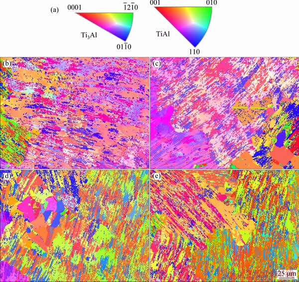
Fig. 9 Crystal orientation-color relation map referring to as inverse pole figure (IPF) (a) and EBSD orientation maps of as-deposited specimen (b) and specimens annealed at 1200 °C (c), 1260 °C (d) and 1320 °C (e)
It can be seen from Fig. 9 that with the increase of annealing temperature, the textures of as-deposited and heat-treated specimens have changed obviously. The representative α2 {0001} and γ {111} pole figures on the upper surfaces of the four specimens are characterized, respectively, and the results are shown in Fig. 10. As can be seen from Fig. 10, after annealing at 1320 °C for 30 min, the texture strengths of α2 {0001} and γ {111} crystal planes are the smallest (the maximum intensities of 57.96 and 20.71 in pole figures, respectively). The main reason for this phenomenon is the increase of the degree of crystallization. Except for 1320 °C, 30 min annealing treatment, the texture strength of the other three α2 {0001} planes is basically unchanged. Among the deposited specimens, the texture strength of γ {111} crystal planes is the highest (maximum intensity of 31.72 in pole figures). However, after annealing at 1200 °C for 30 min and 1260 °C for 30 min, the texture strength of γ {111} crystal planes is basically equal (the maximum intensities of 26.61 and 27.75 in pole figures, respectively). According to the results of mechanical properties, the mechanical properties of annealing treatment at 1260 °C for 30 min are obviously improved compared with anneal treatment at 1200 °C for 30 min. This shows that compared with <001> and <110> directions, grains are predominantly oriented in <010> direction.
3.4 Microhardness
Figure 11 shows the average microhardness of the as-deposited specimen and specimens annealed at different temperatures. The area of each specimen is selected in the middle of the as-deposited specimen, and then 10 points are randomly tested and averaged to obtain the results shown in Fig. 11. As can be seen from Fig. 11, the average Vickers microhardness values of as-deposited specimen and specimens annealed at 1200, 1260 and 1320 °C are HV 409, HV 359, HV 369 and HV 416, respectively. The experimental results show that the mechanical properties of γ-TiAl alloy are mainly related to microstructure type and phase distribution. Equiaxed γ grains have been recognized to be softer than lamellae [18]. This is due to the fact that the nature of dislocations and the ease of slip or twinning in specimens have a similar influence on deformation [19]. Additionally, the volume fraction of the α2 phase is correlated with the hardness of dual-phase TiAl alloy. It has been demonstrated that the dislocations to glide in the α2 phase need significantly larger critical resolved shear stresses compared to the activation of slip in γ-TiAl phase. Therefore, higher microhardness can be obtained in materials with a larger amount of α2 phase [20]. Based upon the above discussion, the response of the as-fabricated material to various applied annealing treatments is completely different. The equiaxed γ microstructures after annealing at 1200 and 1260 °C for 30 min play a crucial role in reducing the microhardness because the deformation of equiaxed γ grains can be facilitated by easy glide of dislocations during the localized plastic deformation. Also, the extremely low volume fraction of α2 phase is also responsible for the reduction in microhardness. Conversely, annealing treatment at 1320 °C for 30 min results in the almost fully lamellar structure as well as large amount of α2 phase, which effectively increases the microhardness.
3.5 Tensile properties and fracture morphologies
The mechanical properties and fracture morphologies of the deposited specimen and specimens annealed at 1200, 1260 and 1320 °C for 30 min are shown in Fig. 12 and 13, respectively. It can be seen from Fig. 12 that the tensile strengths of the specimens annealed at 1260 and 1320 °C for 30 min are almost equal, and their strengths are higher than those of the as-deposited specimen and the specimens annealed at 1200 °C. The experimental results show that the tensile properties of γ-TiAl alloy are strongly affected by the microstructure type, phase distribution and grain size. In general, the interface of layered microstructure provides locations for the crack nucleation sites and yields highly anisotropic and non-uniform deformation [21]. Accordingly, the lamellar grains made of two phases are expected to be the representative multilayer system, and their poor tensile properties at room temperature have been well documented in the literature [22]. In the analysis of microhardness, the effects of the equiaxed γ grains and α2 phase contents on the mechanical properties have been analyzed. Moreover, the tensile properties are inversely proportional to the grain size based on the Hall-Petch relationship. As the grain size decreases, the volume fractions of grain boundaries increase, which is beneficial to the deformation of materials. Consequently, the strength and ductility of coarse grain microstructure are normally lower than those of microstructure with fine grain size. Based upon the above discussion, compared with the as-deposited microstructure, the grain size of specimen annealed at 1320 °C for 30 min plays a more crucial role in increasing the tensile strength and the tensile ductility. Also, the extremely high volume fraction of α2 phase is also responsible for the increase in tensile strength. Compared with the microstructure annealed at 1200 °C for 30 min, the amount of equiaxed γ grains after annealing treatment at 1260 °C for 30 min has increased significantly. In a certain range, the higher the heat treatment temperature is, the more the equiaxed γ grains are. Therefore, the ductility of TiAl alloy after annealing treatment at 1260 °C for 30 min is improved obviously. Furthermore, the acicular α2 phase precipitated in the equiaxed γ grains increases the tensile strength. Therefore, the microstructure annealed at 1260 °C for 30 min not only improves the tensile strength, but also increases the ductility of the alloy.
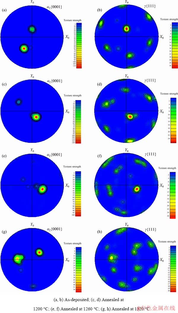
Fig. 10 Texture distribution maps of specimens on α2 {0001} and γ {111} planes
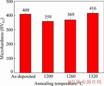
Fig. 11 Effect of annealing temperature on average microhardness
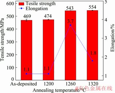
Fig. 12 Effect of annealing temperature on mechanical properties

Fig. 13 Fracture morphologies of different specimens
It can be from the fracture morphologies of the deposited specimen and specimens annealed at 1200, 1260 and 1320 °C for 30 min in Fig. 13, that all of them belong to quasi-cleavage fracture morphology.
4 Conclusions
(1) The microstructure in the middle region of the as-deposited specimen is composed of coarse lamellar colonies. The internal structure of the lamellar colonies is composed of α2+γ lamellae.
(2) With the increase of annealing temperature (1200-1320 °C), the bulk γm phase gradually changes from single γ phase to γ phase + acicular α2 , and finally to γ phase + lamellar α2+ γ phase.
(3) When the specimen is annealed at 1320 °C for 30 min, the basically equal crystals with <001>, <010> and <110> orientations are achieved.
(4) After being annealed at 1260 °C for 30 min and FC, the tensile strength at room temperature is 543.4 MPa and the elongation is 3.7%. Compared with the mechanical properties of as-deposited γ-TiAl alloy (tensile strength 469 MPa, elongation 1.1%), the mechanical properties of the alloy are obviously improved. The fracture morphology of tensile specimens is quasi-cleavage fracture morphology.
References
[1] WANG Qiang, DING Hong-sheng, ZHANG Hai-long, CHEN Rui-run, GUO Jing-jie, FU Heng-zhi. Influence of Mn addition on the microstructure and mechanical properties of a directionally solidified γ-TiAl alloy [J]. Materials Characterization, 2018, 137: 133-141.
[2] ZHAO E T, NIU H Z, ZHANG S Z, FENG L, YANG S Y. Microstructural control and mechanical properties of a β-solidified γ-TiAl alloy Ti-46Al-2Nb-1.5V-1Mo-Y [J]. Materials Science and Engineering A, 2017, 701: 1-6.
[3] WANG Qi, CHEN Rui-run, YANG Yao-hua, WU Shi-ping, GUO Jing-jie, DING Hong-sheng, SU Yan-qing, FU Heng-zhi. Effects of lamellar spacing on microstructural stability and creep properties in β-solidifying γ-TiAl alloy by directional solidification [J]. Materials Science and Engineering A, 2018, 711: 508-514.
[4] LI Wei, LIU Jie, ZHOU Yan, WEN Shi-feng, TAN Jie-wen, LI Shuai, WEI Qing-song, YAN Chun-ze, SHI Yu-sheng. Texture evolution, phase transformation mechanism and nanohardness of selective laser melted Ti-45Al-2Cr-5Nb alloy during multi-step heat treatment process [J]. Intermetallics, 2017, 85: 130-138.
[5] ZHAO Kun, OUYANG Si-hui, LIU Bin, LIANG Xiao-peng, LI Hui-zhong, WANG Yu. Isothermal oxidation behavior of TiAl intermetallics with different oxygen contents [J]. Transactions of Nonferrous Metals Society of China, 2019, 29: 526-533.
[6] CHEN Guo-qing, ZHANG Ge, YIN Qian-xing, ZHANG Bing-gang, FENG Ji-cai. Microstructure evolution of electron beam welded joints of Ti-43Al-9V-0.3Y and Ti-6Al-4V alloys [J]. Materials Letters, 2018, 233: 336-339.
[7] QU H P, LI P, ZHANG S Q, LI A, WANG H M. Microstructure and mechanical property of laser melting deposition (LMD) Ti/TiAl structural gradient material [J]. Materials and Design, 2010, 31: 574-582.
[8] JAN S, CAROLIN K. Selective electron beam melting of Ti-48Al-2Nb-2Cr: Microstructure and aluminium loss [J]. Intermetallics, 2014, 49: 29-35.
[9] QU H P, LI P, ZHANG S Q, LI A, WANG H M. The effects of heat treatment on the microstructure and mechanical property of laser melting deposition γ-TiAl intermetallic alloys [J]. Materials and Design, 2010, 31: 2201-2210.
[10] MA Y, CUIURI D, LI H J, PAN Z X, SHEN C. The effect of postproduction heat treatment on γ-TiAl alloys produced by the GTAW-based additive manufacturing process [J]. Materials Science and Engineering A, 2016, 657: 86-95.
[11] RITTINGHAUS S K, HECHT U, WERNER V, WEISHEIT A. Heat treatment of laser metal deposited TiAl TNM alloy [J]. Intermetallics, 2018, 95: 94-101.
[12] ZHANG Ke-zhao, LEI Zheng-long, CHEN Yan-bin, YANG Ke, BAO Ye-feng. Heat treatment of laser-additive welded Ti2AlNb joints: Microstructure and tensile properties [J]. Materials Science and Engineering A, 2019, 744: 436-444.
[13] CHEN Guo-qing, ZHANG Ge, YIN Qian-xing, ZHANG Bing-gang, FENG Ji-cai. Microstructure evolution of electron beam welded joints of Ti-43Al-9V-0.3Y and Ti-6Al-4V alloys [J]. Materials Letters, 2018, 233: 336-339.
[14] ISMAEEL A, WANG C S. Effect of Nb additions on microstructure and properties of γ-TiAl based alloys fabricated by selective laser melting [J]. Transactions of Nonferrous Metals Society of China, 2019, 29: 1007-1016.
[15] LIU Zhan-qi, XU Guo-jian, MA Rui-xin, ZHENG Wen-tao, HU Fang, HANG Zheng-xiang. Properties of TiAl alloy prepared by additive manufacturing with laser coaxial powder feeding [J]. Chinese Journal of Lasers, 2019, 46(3): 0302016. (in Chinese)
[16] MA Y, CUIURI D, HOYE N, LI H J, PAN Z X. The effect of location on the microstructure and mechanical properties of titanium aluminides produced by additive layer manufacturing using in-situ alloying and gas tungsten arc welding [J]. Materials Science and Engineering A, 2015, 631: 230-240.
[17] THIJS L, KEMPEN K, KRUTH J P, HUMBEECK J V. Fine-structured aluminium products with controllable texture by selective laser melting of pre-alloyed AlSi10Mg powder [J]. Acta Materialia, 2013, 61: 1809-1819.
[18] LIU C M, TIAN X J, TANG H B, WANG H M. Microstructural characterization of laser melting deposited Ti-5Al-5Mo-5V-1Cr-1Fe near β titanium alloy [J]. Journal of Alloy and Compounds, 2013, 572: 17-24.
[19] WU Yu, ZHANG Shu-quan, CHENG Xu, WANG Hua-ming. Investigation on solid-specimen phase transformation in a Ti-47Al-2Cr-2V alloy due to thermal cycling during laser additive manufacturing [J]. Journal of Alloys and Compounds, 2019, 799: 325-333.
[20] CAI Xiao-long, SUN Da-qian, LI Hong-mei, GUO Hong-ling, GU Xiao-yan, ZHAO Zhuo. Microstructure characteristics and mechanical properties of laser-welded joint of γ-TiAl alloy with pure Ti filler metal [J]. Optics and Laser Technology, 2017, 97: 242-247.
[21] ZHAO Wen-yue, PEI Yan-ling, ZHANG Dan-hua, MA Yue, GONG Sheng-kai, XU Hui-bin. The microstructure and tensile property degradation of a gamma-TiAl alloy during isothermal and cyclic high temperature exposures [J]. Intermetallics, 2011, 19: 429-432.
[22] WU Yu, CHENG Xu, ZHANG Shu-quan, LIU Dong, WANG Hua-ming. Microstructure and phase evolution in γ-TiAl/Ti2AlNb dual alloy fabricated by direct metal deposition [J]. Intermetallics, 2019, 106: 26-35.
刘占起,马瑞鑫,徐国建,王文博,苏允海
沈阳工业大学 材料科学与工程学院,沈阳 110870
摘 要:研究激光熔化沉积制备γ-TiAl合金沉积态和不同温度退火态样品的显微组织演变和力学性能。结果表明,沉积态试样的显微组织由细小α2(Ti3Al)+γ片层构成。随着退火温度的升高,块状γm(TiAl)相逐渐由单一γ相→ γ相 + 针状α2相→γ相 + 片层状α2+γ方向转变。与沉积态γ-TiAl合金的力学性能(抗拉强度469 MPa、伸长率1.1%)相比,经1260 °C、30 min、FC退火处理后,试样的室温抗拉强度为543.4 MPa,伸长率为3.7%,其力学性能得到显著提高。
关键词:激光熔化沉积;退火;TiAl合金;显微组织演变;力学性能
(Edited by Wei-ping CHEN)
Foundation item: Project (2017YFB1103600) supported by the National Key Research and Development Program of China
Corresponding author: Guo-jian XU; E-mail: xuguojian1959@qq.com
DOI: 10.1016/S1003-6326(20)65265-7

