Trans. Nonferrous Met. Soc. China 20(2010) s948-s953

Suitability of lost cores in rheocasting process
H. Michels, M. Bünck, A. Bührig-Polaczek
Giesserei-Institut RWTH Aachen, Intzestra?e 5, Aachen 52072, Germany
Received 13 May 2010;accepted 25 June 2010
Abstract:When treated in pressure die casting processes the semi-solid aluminum alloys demand resilient cores which can bear the stress occurring during filling and the final pressure phase. The design of permanent cores is highly restricted in order to maintain removability. Lost cores provide the possibility of complex, undercut geometrical shapes which is mandatory for a variety of casting components. However, eligible materials which show appropriate resilience and proper decomposition properties at the same time, and in the upper echelon of cost-effectiveness, are seldom known. With the semi-solid process suited between HPDC and GDC regarding the core stress, several common and economically efficient lost core systems could be used. A selection of potentially suitable materials was identified and tested. The range of testing comprises widespread sand core-systems (amin-pur-coldbox and CO2-water-glass) as well as materials less commonly used, namely salt, plastic and zinc. Different types of conditioning are applied to enhance the surface properties. The mechanical properties of the sand cores are enhanced by different heat treatment methods during curing. The cores are tested producing a research component cast on a HPDC machine with semi-solid A356 slurry fabricated in the cooling channel process. The cast component was analyzed regarding shape stability, core removability and surface as well as the structure quality. The results show the importance of the surface conditioning for the sand-cores while salt and zinc produce good parts comparable to the reference steel core quality.
Key words: aluminum; semi-solid; rheocasting; cooling channel; lost core; sand; salt; zinc; plastic
1 Introduction
The global need for light alloys rises continuously with aluminum as one of the most important base metals. Increasing demand for light-weight construction materials in the transportation industry adds to the top-level position of aluminium and its alloys as a construction and casting material. The traffic industry remains by far the most important market since the specific advantages of the aluminium here can be fully employed. The widespread procedures of sandcasting as well as LPDC and HPDC concurrently meet their limitations by the rising demand in quality expressed by the processing industry.
Working aluminum alloy as a semi-solid metal (SSM) offers an attractive combination of cast parts with good mechanical qualities like firmness and toughness with the parts being heat treatable at the same time. Adding to that, SSM-cast parts offer weldability and good pressure density. However, SSM-parts processed on HPDC units suffer the same restrictions regarding the core geometry as all PDC parts generally do. On account of the slow and laminar form filling during the casting process in comparison to the conventional HPDC, the application of the lost cores on base of sand meets good conditions in the semi solid process routes. Lost cores are a prerequisite for the realization of cast parts with complex inner geometries.
The subject of the present work is to research the lost cores suitable for the rheocasting process. In the first step presented in this paper, promising materials are researched according to the state of the technology produced and tested.
2 Materials and methods
Cores are characterized by their production route, base core material and post cast fate. They can be removed from the cast part or remain in it. The subject of the present work is those types of cores removed, divided regarding their base matter. Four base materials are chosen to be tested: salt, plastic, sand and zinc based alloys. Table 1 lists a comparison of the top 4 properties of these materials regarding the testing procedures.
Intense endeavor has been made in researching salt cores for example by KS Aluminium Technology [1], Emil Müller GmbH [2], and Toyota Motor Corporation [3]. The research shows that the core systems developed were successfully tested in HPDC processes under close-to-production conditions. This allows us to expect their suitability for SSM Al-rheocasting as well. Zinc, being a classic metal, shows very good mechanical properties typical of its material class and thus naturally is advisable for the designated task. For these two materials, the aptitude made is to be confirmed by scientific experiment with special regard to the chemical reactivity and removability of the cores. The dissolution behavior is also an important topic for the plastic core testing. As one of the few plastics combining advantageous properties such as high mechanical strength, low heat conductivity, good dimension stability and high melting point [4], polyoxmethylen (POM) was chosen for the tests. POM is a high molecular thermoplastic produced by polymerization of formaldehyde in which it unfortunately dissolutes when gasified. It is obvious that the removal is supposed to be achieved avoiding the poisonous gas phase following the decomposition products.
Table 1 Top 4 properties of core materials
The exploratory focus of the program is granted to the sand core systems. While these are known to fail under standard HPDC conditions, the reduced structural stress in SSM processing might open a door for a successful application. The expectations for success even increase when modifications to the core surfaces are applied, enhancing the strength and durability of the core shell [5] .This improvement is realized by tempering and direct chemical conditioning such as dipping in resin and employment of different facings as suggests[6]. Combinatory effects of these conditioning procedures are tested as well. The PUR system used for sand core production and dipping is Isocure 370/5 T1 and Isocure 670/5 T2 by Ashland-Südchemie-Kernfest GmbH. The waterglass binder is type Carsil4000 by FOSECO Int. Ltd. Table 2 lists the core program. Further reference to the core variation is made by using the short for in the last column.
All in all 170 cores are produced for the testing series. The main part, being the sand cores with 87% of the total cores, is produced in the core shooting process. The remaining cores of salt, metal and plastic are produced by master forming and mechanical fabrication out of massive feedstock parts.
Table 2 Core program

Besides the core manufacturing based attempts to increase the success rate of the sand cores, the influence of the commonly applied post pressure in HPDC is explored as well. The working theses regarding this parameter state are as follows.
1)The enormous amount of post-pressure caused by the multiplier following the die fill does not only help to reduce the material defects such as porosity but also induces the crucial stress which leads to the break of the sand cores.
2)SSM cast parts can also be produced in an adequate quality without applying the post pressure (due to the lesser shrinkage of the rheoprocessing route on the HPDC machine and the laminar form filling).
In order to evaluate the working theses, the influence of the post pressure applied in the actual experimental setup is to be carefully examined to create a better understanding for the reasons for the core failure.
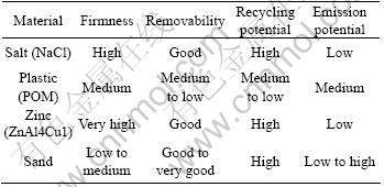
The experiments are conducted on a HPDC machine type Bühler H-630 SC. The semi-solid slurry is produced in the cooling channel process using a A356 alloy (LIT&). The chosen die is well known from the previous research and SSM-cast parts with standard steel cores have been produced with it successfully [7-8]. The cast part is an automobile tie bar (see Fig.1(a)) with a volume of 0. 115 l showing a total length of 414 mm and a mass of 305 g. The compact core shape allows the core to be produced on the various routes described before, which is mandatory due to the different feedstock of the base materials. Fig.1(b) shows the core geometry and dimensions.

Fig.1 Photos of cast part (a) and core geometry (b) (mm)
Understanding the stress and failure route of the sand cores is a prerequisite for a successful determination of the right measures for core modification. Therefore, the dimensional stability of the cores is classified by use of digital image analysis (DIA). The cross section of the cast part directly adjacent to the core is inspected and its absolute area is measured. A comparison is done for every core variation used in the SSM-process by reference between the actual condition and that of a reference steel core. Fig.2 shows the position of the cross section in the cast part (see Fig 2(a)) and the said section sawn and ground down (see Fig. 2(b)). For DIA, the area is colored green using image processing (Fig. 2(c)) but for the purpose of this paper the area is displayed with a hatching. The area is overlaid by the yellow cross section of the reference steel core (white in Fig.2(d)). The excess hatched. respectively green, the area shown in Fig.2(d) represents the deformation caused by the core stress.
By way of information regarding picture resolution (300 dpi) and histogram information, the lowing set of formula is employed to calculate a quantitative parameter for description of the cross section.
 (1)
(1)
 (2)
(2)
 (3)
(3)
 (4)
(4)
The determined value for the area created by the core deformation and the shape of the deformation are related to mould material defects such as roughness, penetration, blowing and sintering. By the way described, a forthright comparison of different sand core variations can be achieved. Besides, the effects of the stress occurring during the SSM-Process are sequentially made visible allowing a detailed reconstruction of the path eventually leading to a failed core starting with the first deformation.
With the knowledge about the occurring defects, appropriate measures of modification can be determined to attempt the reduction of the observed problems, or even completely avoid them, increasing the overall aptitude of the sand cores.

Fig.2 Determination of cross section areas
3 Experimental procedure
In the cooling channel process, the A356 alloy was molten and a melt temperature of 670 to 690?C was set up. A dose of the degassed and skimmed melt was taken from the metal with a pouring spoon and cooled. When the portion temperature reached 630?C it was cast through the channel. Here, the fast heat extraction was realized. Nuclei were formed and the metal was transferred into the semi-solid state. The melt was collected in a faced steel basin and the globularisation of the primary aluminium phase took place [9]. The channel was sloped by 5° and kept at 120-130 ?C. The temperature of the solidifying bolt was measured by two thermocouples, its mass was recorded. Once the metal was at 585 ?C, the steel basin containing the bolt was transferred to the HPDC-aggregate. The bolt was put in the casting chamber and the shot was triggered. After solidification the cast part was taken out and the next shot was prepared. An extensive protocol recorded all relevant information during the casting process.
While the HPDC-aggregate was operated with full post-pressure by standard, the stress of the post-pressure was avoided for part of the core program by utilizing the step shot machine settings generally used for shot curve optimization. These settings still produce a completely cast part but provide the core with less stress by avoiding the final pressure amplitude.
4 Results and discussion
Numerous different standard and fit-to-the-case methods were used in order to extensively evaluate the core suitability and cast part quality. The following results represent a short extract of the whole analysis. The top-most important information is summarized.
4.1 Core stability and contour accuracy
The DIA results of the post pressure less experiments are shown in Table 3. The relative cross section area is also listed (Arel), providing a value for evaluation of the general core stability. Among the core material related flaws, blowing, displacement and ridges are often observed and listed as well, including a tendency (strong/weak) to further judge the grade of their occurrences.
The results show a high stability and contour accuracy for the resin dipped coldbox-amin sand cores (T E and E'). The cross section deviation is quite small and comparable to the reference core. No core break is observed. For all other sand core variations strong displacement, blowing, ridges and core break develops (Fig.3(b)). The results for the waterglass cores type G and H look oddly and it has to be mentioned that those cast parts were not filled completely and thus the cores show very little flaws. However, the arguably quite more resilient core types H', I and I' failed clearly. This allows the assumption of failure for the G and H cores for a completely filled cast part. For this reason, Type F is not tested and failure is anticipated.
Regarding the sequence of sand core material flaws, Fig. 3(a) shows the enlarged cross section of a resin dipped PUR-CB (Type E) sand core visualizing the wall movement. A sinking of the lower cast part wall is frequently observed (Position I> II) as well as a radial wall movement towards the center of the core (Position i> ii).
While types E and E' erform adequately without postpressure applied, all core variants clearly fail when being processed with the standard HPDC parameters used for the steel core. Attempts to adapt the shot curve within the common bounds, regarding the piston and melt velocity, or example, can not produce relief either. All cores show distinct core breaks (see Fig.3(b)).
Meanwhile, salt and plastic cores show a good contour accuracy. The results for the zinc cores are indentical to those of the reference steel core.
4.2 Microstructure analysis
Fig.4 shows the location of the extracted probe (A-B) as well as the embedded sample ready for microscopy.
Table 3 DIA results of post pressure less experiment

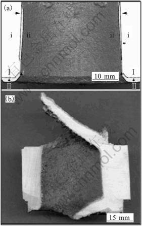
Fig.3 Morphologies showing sand core deformation

Fig.4 Morphologies of sample extraction
The results show the influence of the different cooling capacities. As expected, the eutectic grain size ranges from coarse (sand cores) to fine (zinc cores) with the salt and plastic cores close to the sand cores. No sign of a chemical interaction of salt and molten metal or salt agglomerations can be observed. As well, no sand grains are found in the analyzed probe. The plastic cores show a massively porous surface layer (see Fig.5(a)). For the zinc cores, the grain structure is comparable to the steel cores. However, chemical reactions between the aluminium alloy and the zinc are observed locally. Especially in the corners of the cast part, the zinc is alloying up, forming an unwanted alternated phase (see Fig.5(b)), realloyed areas are colored and outlined white). As a possible course of events, the zinc core melts partially during the casting process increasing its volume and thereby building pressure. This pressure is capable of blasting facing layers and the already solidified cast part shell. Zinc melt intrudes the shell forming mix phases. During further solidification, the aluminium alloy contracts and draws more liquid core alloy into the cast part. This results in a further realloying of the lastly setting eutectic phase. The new mixphases eventually solidifies, forming porosities and hot cracks[7].
4.3 Core decomposition and removal
The decomposition of the sand cores varies for the radial inner and outer sand layers. In case of the PUR-CB cores, the outer shell is supplied with enough heat during the casting to lose the binding effect, making an easy shake out possible. Typically, the waterglass cores are crumbling worse. As for the cores breaking and thus showing a shot-in metal layer (see Fig. 3(b)) the removal of the sand becomes an increased challenge. The core break is always accompanied by surface errors such as roughness, sintering and penetration in the core area (Inner side of the cast part). Due to this, hardly removable sand-metal-zones are formed, which can only be taken away by sandblasting and/or pyrolysis.
The removal of the salt cores is easily achieved in a warm water bed at 80 ℃ fro 20 min. The zinc cores with boron nitride facing can be hammered out just as the steel cores. A smooth surface is observed. Melting the cores out just a few degrees above liquidus point is heavily influenced by the core and cast part geometry. If the liquid zinc is not deducted right away and accumulates it does alloy up and destroy the casting. The POM cores cannot be molten out as anticipated. The high melt viscosity avoids a flow out at normal pressure. Only by raising the temperature up to the decomposition level and thus gassing the plastic out, all materials can be removed. Deep reaching gas inclusions are observed which form during the casting process itself, however.
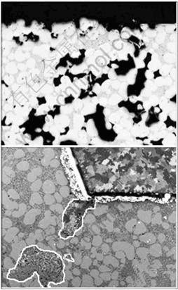
Fig.5Morphologies showing porous surface layer of POM-cores (a) and alloyed up zinc(b)
5 Summary, conclusion and perspective
5.1 Sand cores
None of the tested core variants is suitable for producing a cast part with typical HPDC-parameters. Standard procedure results in core failure (core break) in all cases. It is to be noted that, when operating without high post-pressure, cast parts with good contour accuracy and microstructure density can be produced with the resin dipped PUR-CB cores without core breakage. With the waterglass-cores no such satisfactory results can be achieved. The result for the Type E cores supports the working theories. However, the mechanical properties of parts cast without post pressure are still evaluated.
In both cases, PUR-CB and waterglass, the positive influence of the facing can be observed, producing a smoother surface. While the application of the alcohol-based coating is not a problem with the PUR-CB cores, the surface of the waterglass cores is harmed during this step. The same goes for the resin and waterglass dipping. The removal of the sand cores is mainly influenced by the outer core shell and its conditioning. A core with good form stability is showing a worse removability as a downside. The heat influence during the solidification is not high enough to grant an easy shake out. The stable cores must be sandblasted or heat treated in order to remove the core material. The observed chain of casting errors goes from roughness via penetration to core break. No sign of chemical interactions are observed. Blowing and displacement direct towards an unsufficient compaction of the sand cores. The tempering has no effect recordable with this set up of experiment.
5.2 Non sand cores
The salt cores can be easily removed in a warm water bath. No chemical interaction between the core and cast material can be observed. The cores perform well regarding contour accuracy.
The zinc cores give good results regarding form stability. The passivation of surface reactions resulting in alloying up zinc is urgently to be addressed, however. The boron nitride facing works well for plain surfaces. In case of corners it clearly needs to be optimized.
The POM cores must be deemed unusable due to the massive formation of gas during the casting and solidification. The resulting porous surface layers in the cast part leads to a defective product. The removal of the plastic proves to be disadvantageous as well.
It must be stated that based on the performed experiments and analysis of the tested materials and their variations, only salt can be rated suitable as core material for rheocasting processes at this point of time. With further optimization of the surface conditioning, the PUR-CB cores might be usable as well, if good parts can be produced without high post pressure and the binders shake out behavior is optimized.
References
[1] Aluminium K S, Technologie A G. Entfernbarer kern zum metallgie?en und verfahren zur herstellung eines kerns. DE1 02004006600B4[P]. 2006-03-23.(in German)
[2] Emil Müller GmbH.Wasserl?sliche Salzkerne und Verfahren zur Herstellung wasserl?slicher Salzkerne. WO 2004082866A3[P], 2005-04-05.(in German)
[3] Toyota Motor Corp Pressure resistant core and its manufacturing method. JP 002005066638AA[p], 2005-03-07.
[4] Plastico Kunststoffe Gmbh [EB/OL]. http://www.drehwerkstoffe.de, 2008-02-03.
[5] Rwth Aachen Gieberei Institut. Festigkeitssteigernde,mechanismen bei coldbox-Kernen[M]. Deutschland, 1989
[6] Ryobi Ltd. Production of breakable Core for gigh pressure die casting. JP62-296932[p], 1987-12-24
[7] BüNCK M, WARNKEN N, BüHRIG-POLACZEK A. microstructure evolution of rheocast A356 in consideration of different cooling conditions by means of the cooling channel process[J]. Journal of Materials Processing Technology, 210(5):624-630.
[8] Semi-solid State Processing of alloys and Composites[M]. Busan: Trans Tech Publications, 2006: 513-517.
[9] Sauermann R. Semi-solid processing of tailored aluminium-lithium alloys for automotive applications: Advanced engineering materials[M]. Weinheim: Wiley-VCH Verlag RmbH & Co. KGAA, 2007: 253-258.
[10] Niroumand B, Xia K. 3D Study of the Structure pf Primary Crystals in a Rheocast Al-Cu alloy[J]. Material Science and Engineering,A 2000, 283(1): 70-75
[11] Kugel A. Herstellung von Druckgussteilen mit geometrisch komplexen Innenformen[D]. Uni Leoben, 2004
(Edited by LONG Huai-zhong)
Corresponding author: H. Michels; Tel: +492418098240; E-mail: h.michels@gi.rwth-aachen.de

