
Structure evolution of Cu-based shape memory powder during
mechanical alloying
XIAO Zhu(肖 柱)1, 2, LI Zhou(李 周)1, 2, FANG Mei(方 梅)1, 2,
LUO Ming(罗 明)1, 2, GONG Shen(龚 深)1, 2, TANG Ning(唐 宁)1, 2
1. School of Materials Science and Engineering, Central South University, Changsha 410083, China;
2. Key Laboratory of Nonferrous Metals Science and Engineering, Ministry of Education, Changsha 410083, China
Received 15 July 2007; accepted 10 September 2007
Abstract: The microstructures of shape memory powders of Cu-Al-Ni prepared from pure powders of Cu, Al and Ni using the mechanical alloying(MA) technique were studied by means of hardness measurement, metallograph observation, XRD and SEM. The hardness reaches the peak as the increase in hardness due to plastic deformation and the decrease in hardness due to kinetic annealing reach a balance. The process of MA leads to the formation of a laminated structure, and the layer becomes thinner with an increase in milling time. The pre-alloyed shape memory powder can be formed by milling at 300 r/min for 50 h using a planetary ball mill.
Key words: mechanical alloying (MA); shape memory alloy; microstructure
1 Introduction
The mechanical alloying(MA) technique has been used to produce dispersion-strengthened alloys[1-4] since the discovery of this technique by BENJAMIN[5]. In this process, powders are cold welded together and then fractured repeatedly during the high energy collision between balls as well as between the balls and the wall of the jar. The repeated welding and fracture finally lead to the formation of alloys depending on the different elements to be mechanically alloyed. Different material systems have been investigated.
Among the Cu-based shape memory alloys, Cu-Al-Ni alloy has higher thermal stability than Cu-Zn-Al alloy[6-7]. Nevertheless, Cu-Al-Ni alloys produced by conventional casting are quite brittle[8], which is related to their large elastic anisotropy and large grain size[9]. Moreover, the composition change during casting will shift the transformation temperature. The grain size and composition can be well controlled by using the fabrication process of mechanical alloying (MA) and powder metallurgy(P/M)[10-12]. However, a systemic and appropriate approach to obtain alloyed
shape memory powder has not been done. In this work, mechanical alloying processing with different MA fabrication conditions was applied to convert the Cu, Al, Ni elemental powders mixture to pre-alloyed powders.
2 Experimental
In the MA process, a QM-1F high-energy planetary ball mill with four stainless steel vials was used, and each vial contains hardened steel balls of different sizes, that is, 20, 10 and 6 mm in diameter. The ball-to-powder mass ratio (BPR) is 15?1. The specification of elemental powders and the initial powder mixture is listed in Table 1. The sealed vials were evacuated and then filled with argon gas. The detailed milling processing is listed in Table 2. A small amount of milled powder was removed after certain milling time from the container in an argon glove box and investigated using X-ray diffractometry (XRD) with Cu Kα radiation in Dmax-2500 diffracto- meter. The morphology of the milled powers was observed using Laica EC1 metallographical microscope; the elemental mapping images of the milled powers was observed using scanning electron microscope(SEM) Sirion 200 equipped with EDAX GENESIS 60. The Vickers hardness of powders was measured using a load of 1 N and holding for 15 s on a Vickers hardness machine.
Table 1 Specification and mixture of elemental powders

Table 2 Detailed milling processing of mixture powder

3 Results and discussion
3.1 Morphology of power during mechanical alloying
The evolution in morphology and particle size of the MA powders with milling time is observed and shown in Fig.1. For 300 r/min, the powder particles agglomerate with prolonging milling time. However, the degree of agglomerating of powder particles at 200 r/min for 50 h is obviously lower than that at 300 r/min for 50 h.
MA involves two opposite processes: welding and fracture among powders. In general, at the early stage of milling, welding is in the dominating situation[13]. At this stage, the powders are easily welded, resulting in an increase in the size of powders. The fracture of powders takes place subsequently. However, the tendency of welding and fracture depends on the properties of the powders alloyed. When soft materials are used, welding is excessive, while for brittle materials, fracture dominates. The Cu, Al and Ni powders are soft and ductile at room temperature, and on high speed milling, the temperature of the powders increases; the Cu, Al and Ni powders become even softer and more ductile so that excessive welding occurs. The size of the powders therefore increases. After milling at 300 r/min for 50 h, the size of the powders is observed to increase to 0.5 mm while the distribution of sizes is not uniform.
3.2 Hardness measurement
The hardness of the milled powders as a function of the MA time is given in Fig.2. Initially the hardness of the powders increases rapidly because of work hardening. The maximum hardness is reached after milling for 5 h both at 200 r/min and at 300 r/min; then the hardness decreases until milling for 15 h. It is believed that the decrease in hardness is attributed to the increase in temperature during MA, which causes the hardened powders to be kinetically annealed. After MA for 15 h, hardness increases slightly, which may be attributed to the solution of Ni and Al into Cu. However, hardness measurement in the present study is not a unique measurement to evaluate the degree of MA. For softer materials, the increase in hardness can prevent excessive welding and hence the efficiency of MA can be improved.

Fig.1 Morphology evolution in particle size of MA powder with milling time for different milling speeds: (a) 300 r/min, 5 h; (b) 300 r/min, 25 h; (c) 300 r/min, 50 h; (d) 200 r/min, 50 h
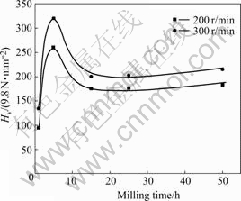
Fig.2 Vickers hardness change of mechanically alloyed powders with milling time
3.3 X-ray diffraction analysis
X-ray diffraction profile of powder milled for different time at various milling speeds is shown in Fig.3. That milled at 100 r/min is shown in Figs.3(a) and

Fig.3 X-ray diffraction patterns of powder milled for different time at various milling speeds: (a, b) 100 r/min; (c-f) 200 r/m; (g-k) 300 r/min
(d). The pattern of 5 h MAed powders is taken as the reference condition where the diffraction peaks of initial elemental powders of Cu, Al and Ni appear. There are no significant changes in the XRD pattern after milling for 50 h. This indicates that the energy is not enough to make these elemental powders form solid solution effectively at 100 r/min using high-energy planetary ball mill.
Figs.3(c)-(f) show the X-ray diffraction profile of powder milled at 200 r/min. With the increase of milling time, the intensities of the diffraction peaks of Al decrease, and those of the Ni almost remain unchanged, which indicates that no significant reaction occurs during milling and the solution of Ni in Cu matrix is more difficult than that of Al. The diffraction peaks of Al and Ni can be seen even after 50 h of milling. It is difficult to enhance the solid solubility of the pre-alloying powders by increasing milling time if the rotation rate is 200 r/min.
X-ray diffraction profiles of powder milled at 300 r/min are shown in Figs.3(g)-(k). The intensities of Cu diffraction peaks increase and those of Al and Ni diffraction peaks decrease with prolonging milling time. Ni and Al peaks almost disappear just after MA for 15 h. The position of Cu diffraction peaks move towards low-angle, which indicates that the lattice parameters of Cu matrix increase with milling time. The X-ray diffraction results, which agree well with the observation by KANEYOSHI et al[14], lead to the conclusion that a single phase solid solution is formed after 25 h MA of the elemental power mixtures at 300 r/min. After further milling, the XRD pattern where the spectrum consisting of Cu diffraction peaks superimposes on top of broad background presents. This broad background is associated with amorphous phase[15].
The width of peaks increases at all tested milling speeds with balling time. It is caused by the decrease of crystallite size and the increase of micro-strain due to a high stress evolved in milling balls impacts. Considering that the increase of peak width mainly consists of the Cauchy part that caused by decrease of crystallite size and Gauss part caused by increase of micro-strain, the XRD profiles can be fitted by Pearson-VII function. Then the average crystallite size D and micro-strain ε can be calculated by substituting the fitted integral breadth into  and ε=
  where
where  is Cauchy integral breadth and
  is Gauss integral breadth, the constant K is 0.9 and λ is 0.154 05 nm. The changes in crystallite size and micro-strain of Cu matrix as a function of milling time are shown in Fig.4. The crystallite size decreases while the micro- strain increases with balling time. The faster the rotation

Fig.4 Change of crystallite size (1, 2, 3) and micro-strain (4, 5, 6) of Cu as function of milling time at different milling speeds
speed, the larger the changes of crystallite size and micro-strain. The Cu powders have an average crystallize size of 10 nm after milling for 50 h at 300 r/min.
3.4 Microstructure analysis
Fig.5 shows the microstructure evolution of the MA powders with milling time at 300 r/min. The laminated structure in the powder particle is seen by plastic deformation and cold welding, and the layer becomes
thin with the increase of milling time. The layer is thick but their thickness are not homogeneous after milling for 5 h (Fig.5(a)). With the increase of milling time, the laminated structure is discontinuous, and the thickness of the layer decrease, as shown in Figs.5(b) and (c). The Cu-matrix becomes homogeneous as the milling time approaches 50 h, as shown in Fig.5(d). However, the layered structure of powders can be clearly observed at 200 r/min for 50 h (Fig.5(a)).
The SEM images and the elemental mapping images of the MAed powders at 200 and 300 r/min for 50 h are shown in Fig.6. The layered structure of Cu, Al, Ni powders can be obviously observed at 200 r/min for 50 h (Fig.6(a)). The elemental mapping images taken from Fig.6(a) are shown in Figs.6(c), (e) and (g). Cu, Al, Ni elements distribute non-uniformly in a powder particle, which illuminates that the alloying of powder mixture is not enough. At 300 r/min for 50 h, the microstructure is shown in Fig.6(b), and the layer structure is thin and only exists in partial area. The elemental mapping images taken from Fig.6(b) are shown in Figs.6(d), (f) and (h). Cu, Al, Ni elements distribute uniformly in a powder particle, and this suggests that the alloying of powder mixture is enough processed. This observation agrees well with the XRD analysis mention above. The Cu-matrix becomes homogeneous.

Fig.5 Typical laminated structure after MA for different time at 300 r/min: (a) 5 h; (b) 15 h; (c) 25 h; (d) 50 h

Fig.6 SEM images and elemental mapping images of powder mechanically alloyed at 200 and 300 r/min: (a) SEM images of powder mechanically alloyed at 200 r/min; (b) SEM images of powder mechanically alloyed at 300 r/min; (c), (e) and (g) Elemental mapping images taken from Fig.6(a); (d), (f) and (h) Elemental mapping images taken from Fig.6(b)
4 Conclusions
1) The pre-alloying shape memory powders can be prepared using MA method. The elemental powders agglomerate during MA. The faster the rotation speed is, the higher the degree of agglomeration occurs.
2) The ball milling speed should be adjusted so that the process of pre-alloying can be completed sufficiently. A single phase of FCC structure with lattice parameter close to that of Cu is produced after milling for 25 h at 300 r/min. The average crystal size of Cu powders after milling for 50 h at 300 r/min is up to 10 nm.
3) The process of MA leads to the formation of a laminated structure, and the layer becomes thin as milling time increases. A homogeneous matrix is obtained after milling at 300 r/min for 50 h; but milling at 200 r/min for 50 h, a mount of elements Al and Ni do not dissolve into the Cu matrix.
References
[1] MENG Jie, JIA Cheng-chang, HE Qing. Fabrication of oxide-reinforced Ni3Al composites by mechanical alloying and spark plasma sintering [J]. Materials Science and Engineering A, 2006, 434(1/2): 246-249.
[2] L?PEZ M, CORREDOR D, CAMURRI C, VERGARA V, JIM?NEZ J. Performance and characterization of dispersion strengthened Cu-TiB2 composite for electrical use [J]. Materials Characterization, 2005, 55(4/5): 252-262.
[3] HU Chia-jung, WU Hsin-ming. Formation of Cu-Zr-Ti amorphous powders with B and Si additions by mechanical alloying technique [J]. Journal of Alloys and Compounds, 2007,434/435: 390-393.
[4] CHENG Xiao-yin, OUYANG Yi-fang, SHI Hong-wei, ZHONG Xia-ping, DU Yong, TAO Xiao-ming. Nano-amorphous (FeAl)1-xZrx alloys prepared by mechanical alloying [J]. Journal of Alloys and Compounds,2006,421(1/2): 314-318.
[5] BENJAMIN J S. Dispersion strengthened superalloys by mechanical alloying [J]. Met Trans, 1970, 10(1): 2943-2951.
[6] KANNARPADY GANESH K, BHATTACHARYYA A. Effect of mechanical and thermal cycling on shape memory properties of high temperature Cu-Al-Ni single crystals [J]. American Society of Mechanical Engineers, Aerospace Division (Publication) AD, 2004, 69:281-285.
[7] RECARTE V, PEREZ-LANDAZABAL J I, IBARRA A. High temperature β phase decomposition process in a Cu-Al-Ni shape memory alloy [J]. Materials Science and Engineering A, 2004, 378(1/2): 238-242.
[8] MIYAZAKI S, OTSUKA K, SAKAMOTO H, SHIMIZU K. Fracture of Cu-Al-Ni shape memory alloy [J]. Transactions of the Japan Institute of Metals, 1981, 22(4): 244-252.
[9] MIYAZAKI S, OTSUKA K. Development of shape memory alloys [J]. ISIJ International, 1989, 29: 353-377.
[10] RODRIGUEZ P P, P?REZ-S?EZ R B, PEREZ-LANDAZABAL J I, RECARTE V, RUANO O A, N? M L, SAN JUAN J. Martensitic transformation in Cu-Al-Ni shape memory alloys obtained by ball milling [J]. Journal De Physique IV: JP, 2003, 1121: 575-578.
[11] RECARTE V, PEREZ-LANDAZABAL J I, CAMPO J, P?REZ-S?EZ R B, N? M L, SAN JUAN J. In situ of the β phase decomposition process in a Cu-al-Ni shape memory alloy processed by powder metallurgy [J]. Journal De Physique IV:JP, 2003, 112: 605-609.
[12] LI Z, PAN Z Y, TANG N, JIANG Y B, LIU N, FANG M, ZHENG F. Cu-Al-Ni-Mn shape memory alloy processed by mechanical alloying and powder metallurgy [J]. Materials Science and Engineering A, 2006, 417(1/2): 225-229.
[13] BENJAMIN J S, VOLIN T E. Mechanism of mechanical alloying [J]. Metallurgical Transactions, 1974, 8(5): 1929-1934.
[14] KANEYOSHI T, TAKAHASHI T, HAYASHI Y, MOTOYAMA M. Microstructure and characteristics of Cu-Al-Ni shape memory alloy prepared by mechanical alloying [J]. Journal of the Japan Institute of Metals, 1992, 56: 517-523.
[15] HUANG H, MCCORMICK P G. Effect of milling conditions on the synthesis of chromium carbides by mechanical alloying [J]. Journal of Alloys and Compounds, 1997, 256(1/2): 258-262.
(Edited by YANG Bing)
Foundation item: Project(05JJ3005) supported by the Natural Science Foundation of Hunan Province, China; Project(20040553069) supported by the PhD Programs of Ministry of Education of China; Project(06MX20) supported by the Mittal Programs of Central South University, China
Corresponding author: LI Zhou; Tel: +86-731-8830264; Fax: +86-731-8876692; E-mail: lizhou6931@163.com

