在纯钛表面制备疏水和抗腐蚀性碳-PTFE复合涂层的性能
来源期刊:中国有色金属学报(英文版)2019年第11期
论文作者:高美连 伍小波 高平平 雷霆 刘春轩 谢志勇
文章页码:2321 - 2330
关键词:碳涂层;钛板;聚四氟乙烯;水热法;疏水性;耐腐蚀性
Key words:carbon coating; Ti plate; polytetrafluoroethylene; hydrothermal method; hydrophobicity; corrosion resistance
摘 要:采用水热法和浸渍法两步工艺在钛板上制备由碳和聚四氟乙烯(PTFE)组成的复合涂层。采用扫描电子显微镜(SEM)、傅里叶变换红外光谱(FTIR)、水接触角计、X射线光电子能谱(XPS)和电化学技术对复合涂层的形貌、组分、疏水和腐蚀性能进行表征,研究不同聚四氟乙烯浓度的浸渍液对复合涂层腐蚀性能的影响。结果表明,当以0.1 mol/L的葡萄糖溶液为碳源、20 wt.% PTFE悬浮液为浸渍液时,聚四氟乙烯均匀分布于所获得的碳复合涂层表面。20 wt.% PTFE浸制的碳涂层与钛板具有良好的结合强度和疏水性,此时润湿角为142.3°,且涂层耐腐蚀性能良好,腐蚀电流密度低至0.0045 μA/cm2。因此,钛基体上制备的碳-PTFE复合涂层具有良好的疏水性和耐腐蚀性,在汽车和金属防腐工业中具有较好的应用前景。
Abstract: Composite coatings consisting of carbon and polytetrafluoroethylene (PTFE) were prepared on Ti alloy substrate by a simple two-step process of hydrothermal and impregnation. The morphology, composition, hydrophobic and corrosion properties of the composite coatings were characterized by scanning electron microscopy (SEM), Fourier transform infrared spectroscopy (FTIR), water contact angle method, X-ray photoelectron spectroscopy (XPS) and electrochemical technique, respectively. The effect of PTFE content on the corrosion properties of the composite coatings was studied. It is found that the composite coating film exhibits a full coverage with uniformly distributed PTFE when 0.1 mol/L of glucose is used as carbon source and 20 wt.% PTFE suspension as impregnating solution. The coating with 20 wt.% PTFE has a good bonding strength with Ti plate and exhibits excellent hydrophobic property with a water contact angle of 142.3° as well as superior corrosion resistance with corrosion current density as low as 0.0045 μA/cm2. With regard to its excellent hydrophobicity and corrosion resistance, the carbon-PTFE composite coating may find potential application in automobiles and metal corrosion industries.
Trans. Nonferrous Met. Soc. China 29(2019) 2321-2330
Mei-lian GAO1.2, Xiao-bo WU1,2, Ping-ping GAO2,3, Ting LEI2, Chun-xuan LIU4, Zhi-yong XIE2
1. College of Metallurgy and Materials Engineering, Hunan University of Technology, Zhuzhou 412000, China;
2. State Key Laboratory of Powder Metallurgy, Central South University, Changsha 410083, China;
3. Hunan Provincial Key Laboratory of Vehicle and Transmission System, Hunan Institute of Engineering, Xiangtan 411104, China;
4. Hunan Gold Sky Aluminum Industry High-tech Co., Ltd., Changsha 410205, China
Received 26 November 2018; accepted 18 September 2019
Abstract: Composite coatings consisting of carbon and polytetrafluoroethylene (PTFE) were prepared on Ti alloy substrate by a simple two-step process of hydrothermal and impregnation. The morphology, composition, hydrophobic and corrosion properties of the composite coatings were characterized by scanning electron microscopy (SEM), Fourier transform infrared spectroscopy (FTIR), water contact angle method, X-ray photoelectron spectroscopy (XPS) and electrochemical technique, respectively. The effect of PTFE content on the corrosion properties of the composite coatings was studied. It is found that the composite coating film exhibits a full coverage with uniformly distributed PTFE when 0.1 mol/L of glucose is used as carbon source and 20 wt.% PTFE suspension as impregnating solution. The coating with 20 wt.% PTFE has a good bonding strength with Ti plate and exhibits excellent hydrophobic property with a water contact angle of 142.3° as well as superior corrosion resistance with corrosion current density as low as 0.0045 μA/cm2. With regard to its excellent hydrophobicity and corrosion resistance, the carbon-PTFE composite coating may find potential application in automobiles and metal corrosion industries.
Key words: carbon coating; Ti plate; polytetrafluoroethylene; hydrothermal method; hydrophobicity; corrosion resistance
1 Introduction
Titanium (Ti) is abundant on earth and has become one of the research focuses [1]. Ti and its alloys have outstanding corrosion resistance due to the thin oxide protective layer formed spontaneously on their surfaces when exposed to aerated environment, which allows them to be used in severe working condition, such as offshore, acidic environment, aerospace, automotive, high temperature and chemical and food industries [2,3]. Nevertheless, commercial pure Ti and its alloys may suffer localized corrosion in hot salty water and acidic solution containing fluoride [4]. Therefore, surface treatment has been considered as an effective way to improve their corrosion resistance in highly aggressive environment [5].
At present, the surface modification techniques of Ti and its alloy including electroplating, electroless plating, magnetron sputtering, active screen plasma nitriding (ASPN) and chemical vapor deposition (CVD) have been extensively investigated [6-8]. For example, RAO and PUSHPAVANAM [8] investigated the effect of deposition parameters on the morphology and crystallographic texture of titanium alloy by electroless plating. CHANG et al [9] investigated various TiO2/Ag coatings deposited onto pure Ti plate samples using an unbalanced magnetron-based sputtering process and an excellent antibacterial performance of the coating was found. ASKARI et al [10] reported a well adhered nano-crystalline diamond film on pure Ti substrate by using a microwave plasma assisted chemical vapor deposition (MWPCVD) system in the environment of Ar, CH4 and H2 gases at 600 °C for 10 h. It is well-known that CVD method normally leads to some adverse consequences, such as grain growth, embrittlement and deformation. Instead, physical vapor deposition (PVD) process is more widely used. But it also has the disadvantages such as high production process requirements, high equipment input and limited product size.
To date, the development of low-cost, eco-friendly, high-performance coatings on Ti surface has been a challenge. Recently, metal ceramic coatings such as CrC, TiN and Ti6Al4V and Ni-Cu-P/n-TiN have been paid much attention due to their excellent wear resistance and corrosion resistance [11-15]. The results show that the metal ceramic coatings exhibit low corrosion current density in strong acid environment (0.5 mol/L H2SO4 and 2×10⁻⁶ HF at 70 °C). In this work, a simple two-step process involving hydrothermal and impregnation was studied for the preparation of carbon-PTFE film on Ti substrate. The microstructure, corrosion resistance, hydrophobic and corrosion properties of the as-prepared composite coating films were investigated. Furthermore, the effect of PTFE on corrosion resistance and interfacial properties and a formation mechanism of carbon-PTFE coating were discussed.
2 Experimental
2.1 Pretreatment of Ti plate
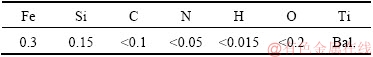
Ti plates with dimensions of 20 mm × 20 mm × 0.2 mm were used as the substrate in this study, and their chemical compositions are presented in Table 1. The Ti plates were polished with 800, 1500 and 2000 grit silicon abrasive papers, followed by ultrasonic cleaning in acetone for 10 min and washing by distilled water, respectively. Then, the Ti plate was immersed in 8 mol/L NaOH solution for 24 h, finally washed in distilled water and dried in air. All above chemicals are analytically pure and purchased from Aladdin Company (Shanghai, China).
Table 1 Chemical compositions of Ti plates (wt.%)
2.2 Preparation of carbon and carbon-PTFE coating
The glucose was purchased from Aladdin Company (Shanghai, China) as carbon source and the poly- tetrafluoroethylene (PTFE, Dupont Production, UAS) was employed as an additive to optimize carbon coating. The carbon precursor films were prepared via a hydrothermal method using glucose solution with concentration of 0.1 mol/L for 10 h on the pre-treated Ti plates at 170 °C. Then, the coatings were carbonized at 450 °C for 2 h under Ar atmosphere. Afterwards, the heat-treated carbon films on Ti plates were immersed in 5, 10, 15, 20 and 30 wt.% PTFE suspension solutions, respectively. Finally, the soaked samples were incubated in a tube furnace at 350 °C for 2 h under Ar atmosphere. The resulting composite coating samples were named as S1, S2, S3, S4 and S5, respectively. Figure 1 shows the procedure for the preparation of carbon composite coating.
2.3 Coating characterization
The morphologies of the as-prepared composite coatings were observed by field emission scanning electron microscope (SEM, JEOL.ISM-7600F), transmission electron microscopy (TEM, JEM-2100F). The adhesion between the substrate and the coating was measured by automatic scratch instrument (HT-3002, head diameter 100 nm, 0.03 N). The functional groups of the coatings were verified by Fourier transform infrared spectroscopy (FTIR, Madison Nicolet-6700). Static contact angles and sliding angles of the coatings were characterized with a Drop Meter A-100P optical contact angle meter (OCA20). X-ray photoelectron spectroscopy (XPS) was used to analyze the corrosion mechanism of the coatings. Tafel polarization curve and electrochemical impedance spectroscopy (EIS) measurements were performed in a solution containing 0.5 mol/L H2SO4 and 2×10⁻⁶ HF at 70 °C through an electrochemical workstation (CHI 660e, Shanghai Chenhua Instrument Co., Ltd., China). All the electrochemical measurements were performed and repeated five times. The Ti plate and coating specimens were used as working electrodes sealed with epoxy resins to get an exposed square area of 1 cm2, while a saturated calomel electrode (SCE) and a Pt sheet were applied as reference electrode and counter electrode, respectively. The specimens were firstly immersed in corrosive medium to obtain stable open circuit potential (φocp). The polarization curves were obtained at a sweep rate of 1 mV/s from -0.8 to 0.8 V. The electrochemical impedance spectroscopy (EIS) measurements were carried out at open circuit potential with amplitude of 5 mV in the frequency range from 0.01 Hz to 100 kHz.

Fig. 1 Schematic illustration of procedure for preparation of carbon composite coating
In this work, scratch test was used to evaluate the binding strength between coating film and underlying Ti substrate for Sample S4. The main technical indexes of the scratcher are as follows: (1) loading range (automatic continuous loading) 0.03-30 N; (2) scratch speed 4 mm/min; (3) loading rate 60 N/min; (4) measuring range (automatic) 2-30 mm; (5) head diamond (R=100 μm); (6) scratch length 2 mm.
3 Results and discussion
3.1 Characterization of coatings

Fig. 2 SEM images of surface morphology
Figure 2 shows the SEM images of the surface morphology of Ti plates with and without coatings. The surface appearance of pure Ti plate after pre-treatment in 8 mol/L NaOH solution for 24 h is shown in Fig. 2(a). It is shown that a porous network structure with pore diameter of 60-150 nm was formed on the Ti plate after etching in NaOH solution. In this work, prior to alkali treatment, Ti substrate was subjected to an initial acid treatment to remove oil and impurities on the surface [16,17]. In alkaline solution, the TiO2 layer was partially dissolved and the exposed metallic Ti would react further with alkaline solution. It was reported that the reaction between Ti and alkaline produced sodium titanate hydrogel layer (NaxH2-xTiyO2y+1・nH2O) [18,19], which can be removed by washing with distilled water or ultrasonic cleaning [20,21]. Thus, a large amount of pits are formed on Ti surface. Notably, the as-formed nano-pits are normally concave which are beneficial to improving the mechanical binding strength between the coating film and substrate. The surface morphology of carbon coating in Fig. 2(b) exhibits a full coverage when 0.1 mol/L of glucose is used as carbon source. In general, further condensation and carbonization by heat treatment would result in volume contraction, giving rise to small pits on the carbon coating surface [22]. This result implies that the pure carbon film with pits is not enough to provide protection of titanium matrix. Reasonably, if these small pits in carbon film could be filled, a dense carbon film and an improved protective effect are anticipated. Figure 2(c) shows the surface morphology of the carbon-PTFE composite coating (Sample S1) by immersing in 5 wt.% PTFE suspension solution. Apparently, some pits are still observable, indicative of incomplete filling of the holes in carbon film. In comparison with Sample S1, Sample S2 exhibits a smoother appearance with some visible holes (Fig. 2(d)).
Interestingly, Samples S3 and S4 show smooth and dense composite films without pits, indicating a good filling by PTFE as shown in Figs. 2(e) and (f) when the PTFE content in immersion solution are 15 wt.% and 20 wt.%, respectively. The EDS analysis of Sample S4 shows that the F element (the molecular formula of PTFE is (C2F4)n) of the film reaches 5.85 wt.%. When the content of PTFE suspension is 30 wt.%, Sample S5 exhibits similar surface morphology as that of Sample S4 but becomes rougher.
Figure 3 shows the TEM and HRTEM images of Sample S4. Notably, an inter planar spacing of 0.27 nm is measured, associating with Ti plate [23]. At the same time, no cracks and holes in the interphase between carbon film and Ti substrate are observed, indicating a good bonding strength between them.
In order to characterize carbon and carbon-PTFE film on Ti plate, XPS and FTIR analyses were performed. The results are presented in Figs. 4(a) and (b), respectively. Figures 4(c) and (d) show high resolution C 1s spectra of carbon film and carbon-PTFE film, respectively. The mole fractions derived from the areas of the characteristic photoelectron peaks are listed in Table 2. The deconvolution of C 1s spectra of carbon film presents three peaks associated with C―C (88.3 at.%, 284.6 eV), C―O (7.2 at.%, 286.4 eV) and C=O (4.5 at.%, 288.9 eV) [10,24], respectively. Similarly, the C 1s spectra of carbon-PTFE film present five peaks associated with C―C (26.1 at.%, 284.8 eV), C―O (6.4 at.%, 286.4 eV), C=O (9.2 at.%, 288.9 eV), C―F (30.8 at.%, 291.6 eV) and C―F3/C―OF2 (27.4 at.%, 293.1 eV).
In Table 2, the total sum of C―O and C=O is 11.7 at.% in carbon film, while it is 15.6 at.% in carbon- PTFE coating. Additionally, content of C―F3/C―OF2 in composite film reaches 27.4 at.% (main chemical bonds of PTFE is C―F2), implying that the PTFE in the coating is bonded with oxygen groups. These oxygen groups are probably introduced by the reaction between oxygen species and carbon atoms during the heat treatment process at 350 °C. The XPS results also indicate that the PTFE would adsorb oxygen-containing groups and generate C―F3/C―OF2 on the surface of carbon-PTFE coating during heat treatment process [25-27], which means that the crystallinity and density of coating are related to the formation of C―F3/C―OF2 bonds [25]. Base on the above reasons, the composite coating thus shows better interfacial combination when the carbon coating is impregnated in 20 wt.% PTFE suspension solution.

Fig. 3 TEM (a) and HRTEM (b) images of Sample S4
The chemical structure of the films was also analyzed by infrared spectroscopy as shown in Fig. 4(b). Obviously, all the films exhibit strong absorption bands at 1100 cm-1, which are typically attributed to the C―C stretching vibration of carbon. It is noted that some new spectrum peaks observed in carbon-PTFE at 850, 950 cm-1 (C―H vibration) and 1710 cm-1 are attributed to C=O and C―O stretching absorptions, corresponding to carbonyl and carboxyl groups [28], indicative of the existence of massive carbonyl and carboxyl groups on the surface of carbon-PTFE, respectively, compared with carbon film. The absorption band at 1650 cm-1 is attributed to the C=C stretching vibration from graphitic domains. The peaks at 1100- 1300 cm-1 are assigned to the stretching modes of C―F2 and C―F3/C―OF2 from PTFE [29]. The F electron cloud from PTFE would interact with the electron cloud of functional group (C=O), which can improve the bonding strength of PTFE and matrix carbon [30,31]. The peaks at 2300-2350 cm-1 are assigned to the stretching modes of C=O [32]. The peaks around 3500 cm-1 are assigned to the stretching modes of ―OH. Therefore, these observations validate the formation of chemical binding between carbon and PTFE in coating, which is beneficial to the stability of the composite coating film.

Fig. 4 Survey spectra of coatings
Table 2 Fitting parameters and relative quantity of compounds for C 1s spectra of carbon film and carbon-PTFE film by XPS

The water contact angles (WCAs) of the coatings are summarized in Fig. 5. Notably, the listed contact angle value is obtained by averaging values measured at 5 points. The carbon coating film demonstrates a WCA of 83.03° (Fig. 5(a)). Interestingly, the hydrophobic properties of the composite carbon coating film are greatly enhanced with the addition of PTFE. As shown in Fig. 5(e), when 20 wt.% PTFE suspension solution is used as impregnating solution, the as-obtained carbon- PTFE coating film exhibits the best hydrophobic property with a WCA of 142.3°. It is also noteworthy that the hydrophobicity of the composite coating film decreases as the PTFE content exceeds 20 wt.%.
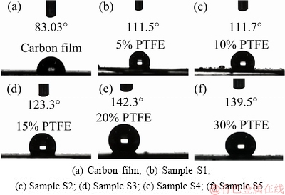
Fig. 5 Optical images of water droplets on carbon and carbon-PTFE film surfaces
Fluorine ion has strong polarity, strong electro- negativity and small atomic radius, which makes the C―F bond extremely stable [33]. Water is a polar molecule and can form hydrogen bonds internally. In contrast, the PTFE molecules show very weak polarity with low surface free energy. Therefore, it is difficult for PTFE to form hydrogen bonds with water [29,34]. The insulating nature of PTFE prevents the transportation of electrons on the coating surface and thus provides the best hydrophobicity [35]. Hydrophobicity is not only related to special molecular structure of PTFE, but also dependent on the surface flatness [36,37]. It is widely believed that rougher surface tends to exhibit worse hydrophobic performance. Accordingly, Sample S4 possesses the best hydrophobicity due to the combined effect of specific PTFE and the smooth surface appearance.
3.2 Corrosion resistance of carbon-PTFE coating
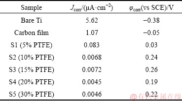
Corrosion resistance is one of the most important criterions in evaluating the performance of coatings. The potentiodynamic polarization (Tafel) and EIS results of bare Ti, carbon-coated and carbon-PTFE-coated Ti specimens in the simulated solution containing 0.5 mol/L H2SO4 and 2×10⁻⁶ HF at 70 °C are shown in Figs. 6 and 7, respectively. The corrosion current densities and corrosion potentials of pure Ti, carbon film, Samples S1, S2,S3, S4 and S5 are summarized in Table 3. As seen in Table 3, the corrosion potential of carbon film shifts in the positive direction and the corrosion current density decreases in comparison with bare Ti. The error ranges are also listed in Table 3. After incorporation of PTFE into carbon film, the corrosion potential of carbon-PTFE shifts more positively and the corrosion current further decreases. Sample S4 shows the lowest corrosion current density of 0.0045 μA/cm2. Evidently, the addition of PTFE is beneficial to the improvement of corrosion resistance of carbon coating.

Fig. 6 Tafel curves of bare Ti, carbon and carbon-PTFE composite films

Fig. 7 EIS curves of bare Ti, carbon and carbon-PTFE composite films
Table 3 Polarization current densities and potentials of all samples
EIS analysis was performed to characterize the corrosion kinetics of coatings in a solution containing 0.5 mol/L H2SO4 and 2×10⁻⁶ HF at 70 °C. Figures 7(a) and (b) show the Nyquist plots and enlarged Nyquist plots, respectively, and Fig. 7(c) shows Bode plots. Two semicircles in high frequency and low frequency zones are distinguishable in Nyquist diagrams of all samples, which is also verified by the Bode diagram in Fig. 7(c). Therefore, two time constants are considered to simulate the EIS and the corresponding equivalent circuit model is shown in Fig. 7(d), where Rct is ascribed to the charge transfer resistance at the coating film/solution interface. Rs represents the solution resistance. Rcoat is ascribed to the resistance of coating film. CPE1 and CPE2 denote the constant phase elements of the coating and double layer [38], respectively. The electrical equivalent circuit parameters are listed in Table 4. The Rcoat values of samples increased with the increase of PTFE content. This is mainly because PTFE is a good insulating material. The higher the content of PTFE on the coating surface is, the higher resistance of the coating is, accordingly, Sample S5 has the highest Rcoat value of 2.35×10⁵ Ω・cm2 among all the samples. In general, the larger the Rct is, the more difficult the transfer of charges between solution and the coating surface is, and thus the corrosion rate decreases. As revealed in Table 4, the bare C and Ti show the lowest impedance as compared with other coating samples, whereas Sample S4 has the highest Rct value of 4.63×10⁶ Ω・cm2 among all the samples. Accordingly, Sample S4 exhibits the best corrosion resistance, which is in a good agreement with Tafel result. Consequently, the composite carbon coating with PTFE on Ti shows obviously effective protection. In conclusion, it is inferred that the incorporation of PTFE results in the filling of pits in carbon film, leading to the formation of compact composite film. Besides, the formation of chemical bonds (C―F3/C―OF2 band) enhances the interfacial binding strength between carbon film and PTFE particles. Accordingly, the composite film works as a barrier to effectively prevent the permeation of corrosion solution from coating film surface into the underlying substrate and thus endow the composite film the best corrosion resistance.
The corrosion process can be concluded as follows.
Firstly, carbon with active sites on carbon film surface reacted with water as follows [39-41]:
C+2H2O→CO2+4H+4e, φ≥0.207 V (1)
Then, the oxygen molecules aggregate to form more active sites on matrix surface for further corrosion [42]. Lastly, the corroded holes become deeper and some carbon sheets detach and fall into the solution. In order to illustrate the process, the schematic diagram is shown in Fig. 8. On the one hand, the C―O and C=O groups on carbon film can bond with fluorine atoms and thus enhance the interfacial properties between carbon and PTFE. On the other hand, PTFE hydrophobic network forms and works as a barrier layer between carbon film and corrosive medium for corrosion attack.
3.3 Interface adhesion and thickness of carbon-PTFE coating
Table 4 Electrochemical parameters obtained from simulated equivalent circuits by EIS


Fig. 8 Corrosion evolution diagrams of carbon film (a) and carbon-PTFE film (b)
Scratch test is a simple approach widely used to evaluate the interfacial bonding strength between coating and underlying substrate. Figure 9 shows the SEM image of the scratch and the enlarged images of assigned areas and curves of applied load against scan distance [43]. Apparently, it can be seen in Fig. 9(h) that there are three curves, corresponding to ultrasonic signal (acoustic emission (AE) sensitivity)-scratch length, load-scratch length and penetration depth-scratch length, respectively. For the first time, the load calibration of the ultrasonic signal is the critical load Lc. It is known from the test that the coating first mutates at about 5 N, and the maximum penetration depth is 2.5 μm. In general, based on the test curve and SEM images of the scratched surface, the critical load Lc representing the interface binding force can be judged. As shown in Fig. 9(a), when the load is low, scratch is smooth inside. As the load increases further, the wear particles exist in the coatings. Plastic deformation is gradually formed when particles are entrapped into the substrate. The friction between wear particles and the head results in the increase of acoustic emission signal and cut width. Under the continuously increasing load, a few cracks appear and the load reaches the critical load of the cohesive failure of film as shown in Fig. 9(d). With further increase of the load, the whole coating is peeled off from the substrate as shown in Fig. 9(e). According to the acoustic emission test curve (Fig. 9(h)), the signal is stable before 20 N and the acoustic emission signal at 20-25 N is fluctuated. The surrounding coating of the scratches is stripped from the substrate and the metal matrix appears at the end of the scratch and an applied load of 28 N is judged. This load of 28 N represents the binding force between the coating and substrate.
A cross-section scanning test is further performed to disclose the coating thickness, which is about 2.1 μm (Figs. 9(f) and (g)). This indicates that the penetration depth in the critical load state exceeds the coating thickness.

Fig. 9 SEM images and scratch test curves of Sample S4 after micro-scratch test
4 Conclusions
(1) A new composite carbon coating composed of carbon-PTFE on Ti plate is prepared successfully by hydrothermal and impregnation method.
(2) The composite film exhibits excellent corrosion resistance and hydrophobic performance. The optimal heat treatment temperature for the formation of tight bonding between carbon and PTFE is 350 °C, at which a smooth coating surface could be obtained.
(3) The carbon-PTFE composite coating prepared by immersing in PTFE suspension solution (20 wt.%) shows smoothest surface morphology, the lowest corrosion current density (0.0045 μA/cm2) and highest wetting angle (142.3°).
(4) The outstanding performance indicates that this carbon-PTFE composite coating could be applied on the Ti bipolar plate of PEMFCs or other Ti components working in the corrosive environments.
References
[1] ZHECHEVA A, WEI S, MALINOV S, LONG A. Enhancing the microstructure and properties of titanium alloys through nitriding and other surface engineering methods [J]. Surface & Coatings Technology, 2005, 200(7): 2192-2207.
[2] PRANDO D, BRENNA A, DIAMANTI M V, BERETTA S, BOLZONI F, ORMELLESE M, PEDEFERRI M. Corrosion of titanium. Part 1: Aggressive environments and main forms of degradation [J]. Journal of Applied Biomaterials & Functional Materials, 2017, 15(4): 291-302.
[3] LI Cong-bo, CHEN De-hua, CHEN Wei-wei, WANG Lu, LUO Da-wei. Corrosion behavior of TiZrNiCuBe metallic glass coatings synthesized by electrospark deposition [J]. Corrosion Science, 2014, 84: 96-102.
[4] PRANDO D, BRENNA A, BOLZONI F M, DIAMANTI M V, PEDEFERRIE M, ORMELLESE M. Electrochemical anodizing treatment to enhance localized corrosion resistance of pure titanium [J]. Journal of Applied Biomaterials & Functional Materials, 2017, 15(1): 19-24.
[5] MABILLEAU G, BOURDON S, JOLY GUILLOU M L, FILMON R, BASLE M F, CHAPPARD D. Influence of fluoride, hydrogen peroxide and lactic acid on the corrosion resistance of commercially pure titanium [J]. Acta Biomaterialia, 2006, 2(1): 121-129.
[6] ELSAKA S E, HAMOUDA I M, ELEWADY Y A, ABOUELATTA O B, SWAIN M V. Effect of chromium interlayer on the shear bond strength between porcelain and pure titanium [J]. Dental Materials, 2010, 26(8): 793-798.
[7] CHEN S H, TSAI W L, CHEN P C, FANG A, SAY W C. Influence of applied voltages on mechanical properties and in-vitro performances of electroplated hydroxyapatite coatings on pure titanium [J]. Journal of the Electrochemical Society, 2016, 163(7): 305-308.
[8] RAO C R K, PUSHPAVANAM M. Electroless deposition of platinum on titanium substrates [J]. Materials Chemistry and Physics, 2001, 68(1-3): 62-65.
[9] CHANG Y Y, LAI C H, HSU J T, TANG C H, LIAO W C, HUANG H L. Antibacterial properties and human gingival fibroblast cell compatibility of TiO2/Ag compound coatings and ZnO films on titanium-based material [J]. Clinical Oral Investigations, 2012, 16(1): 95-100.
[10] ASKARI S J, AKHTAR F, CHEN G C, HE Q, WANG F Y, MENG X M. Synthesis and characterization of nano-crystalline CVD diamond film on pure titanium using Ar/CH4/H2 gas mixture [J]. Materials Letters, 2007, 61(11-12): 2139-2142.
[11] WEI Zhao-yong, YI Lin, PENG Pei-yun, LIN fa. Influence of Cr-C film composition on electrical and corrosion properties of 316L stainless steel as bipolar plates for PEMFCs [J]. International Journal of Hydrogen Energy, 2016, 41(2): 1142-1150.
[12] ZGHANG D M, DUAN L T, GUO L, TUAN W H. Corrosion behavior of TiN-coated stainless steel as bipolar plate for proton exchange membrane fuel cell [J]. International Journal of Hydrogen Energy, 2010, 35(8): 3721-3726.
[13] LI S M, ZHU M Q, LIU J H,YU M, ZHAND J D.new insights into enhancement of sodium hypochlorite on formation and properties of anodic films on Ti6Al4V alloy [J]. Journal Cent South Univ, 2018, 25: 976-986.
[14] ZHOU H M, HU X Y, L J. Corrosion behaviors and mechanism of electroless Ni-Cu-P/n-TiN cmposite coating [J]. Journal Cent South Univ, 2018, 25: 1350-1357.
[15] ZHAND J, XU Q, HU Y, MAO C,ZHOU X J,LU X Z,ZHAND M J,TONG Y G, TANG K, PENG P. Interfacial bonding mechanism and adhesive transfer of brazed diamond with Ni-based filler alloy: First-principles and experimental perspective [J]. Carbon 2019,153: 104-115.
[16] KIM H M, MIYAJI F, KOKUBO T, NAKAMURA T. Preparation of bioactive Ti and its alloys via simple chemical surface treatment [J]. Journal of Biomedical Materials Research Part A, 1996, 32(3): 409-417.
[17] XIONG J Y, LI Y C, WANG X J, ,WEN C E. Mechanical properties and bioactive surface modification via alkali-heat treatment of a porous Ti-18Nb-4Sn alloy for biomedical applications [J]. Acta Biomaterialia, 2008, 4(6): 1963-1968.
[18] ALADJEM A. Anodic oxidation of titanium and its alloys [J]. Journal of Materials Science, 1973, 8(5): 688-704.
[19] LIANG Fang-hui, ZHOU Lian, WANG Ke-guang. Apatite formation on porous titanium by alkali and heat-treatment [J]. Surface & Coatings Technology, 2003, 165(2): 133-139.
[20] KOKUBO T, YAMAGUCHI S. Novel bioactive titanate layers formed on Ti metal and its alloys by chemical treatments [J]. Materials, 2010, 3(1): 48-63.
[21] LEE B H, KIM Y D, SHIN J H, LEE K H. Surface modification by alkali and heat treatments in titanium alloys [J]. Journal of Biomedical Materials Research, 2002, 61(3): 466-473.
[22] LIBRA J A, RO K S, KAMMANN C, FUNKE A, BERGE N D, NEUBAUER Y. TITIRICI M M, FUHNER C, BENS O, KERN J, EMMERICH K H. Hydrothermal carbonization of biomass residuals: A comparative review of the chemistry, processes and applications of wet and dry pyrolysis [J]. Biofuels, 2014, 2(1): 71-106.
[23] CHANZY H, FOLDA T, SMITH P, GARDNER K, REVOL J F. Lattice imaging in polytetrafluoroethylene single crystals [J]. Journal of Materials Science Letters, 1986, 5(10): 1045-1047.
[24] VALERIE P, GREGORY B, CHARLESJOUD J, OLIVIER L, ALEJANDRO A F. XPS investigations of the proton exchange membrane fuel cell active layers aging: Characterization of the mitigating role of an anodic CO contamination on cathode degradation [J]. Journal of Power Sources, 2011, 196(5): 2530-2538.
[25] BECKFORD S, ZOU M. Wear resistant PTFE thin film enabled by a polydopamine adhesive layer [J]. Applied Surface Science, 2014, 292: 350-356.
[26] LIU S L, FU C L, GU A Q, YU Z L. Structural changes of polytetrafluoroethylene during irradiation in oxygen [J]. Radiation Physics and Chemistry, 2015, 109: 1-5.
[27] UL AHAD I, BUTRUK B, AYELE M, BUDNER B, BARTNIK A, FIEDOROWICZ H, CIACH T, BRABAZON D. Extreme ultraviolet (EUV) surface modification of polytetrafluoroethylene (PTFE) for control of biocompatibility [J]. Nuclear Instruments & Methods in Physics Research Section B-Beam Interactions with Materials and Atoms, 2015, 364: 98-107.
[28] LIU Yan-yun, ZHANG Dong, SHANG Yu, GUO Chao. A simple and efficient electrochemical reductive method for graphene oxide [J]. Material Science, 2014, 37(6): 1529-1533.
[29] GAO Ping-ping, XIE Zhi-yong, OUYANG Chun, TAO Tao, WU Xiao-bo, HUANG Qi-zhong. Electrochemical characteristics and interfacial contact resistance of Ni-P/TiN/PTFE coatings on Ti bipolar plates [J]. Journal of Solid State Electrochemistry, 2018, 22(7): 1971-1981.
[30] WU Bing-bing, ZHAO Ming, SHI Wei-yu, LIU Wen-ming, LIU Jian-guo, XING Dan-min, YAO Ying-fang, HOU Zhong-jun, MING Ping-wen, GU Jun, ZOU Zhi-gang. The degradation study of Nafion/PTFE composite membrane in PEM fuel cell under accelerated stress tests [J]. International Journal of Hydrogen Energy, 2014, 39(26): 14381-14390.
[31] SONG H S, YU H W, ZHU L J, XUE L X, WU D C, CHEN H. Durable hydrophilic surface modification for PTFE hollow fiber membranes [J]. Reactive and Functional Polymers, 2017, 114: 110-117.
[32] HERNANDO S, ARNOLDREY B, GENE Q, JANELLAMAE R, MATTHEW BRYAN P, VILLANUEVA, HENRY J. Fourier transform infrared spectroscopy (FTIR) characterization of oxygen-ion treated polytetrafluoroethylene (PTFE) materials [C]// Proceedings of the 28th Samahang Pisikang Pilipinas Physics Congress, Antipolo City, Rizal, Philippines, 2010, 7: 1-4.
[33] ZHOU Yi, LI Meng-yao, ZHONG Xian, ZHU Zhi-ping, DENG Pan, LIU Hai. Hydrophobic composite coatings with photocatalytic self-cleaning properties by micro/nanoparticles mixed with fluorocarbon resin [J]. Ceramics International, 2015, 41(4): 5341-5347.
[34] CARBONE E A D, BOUCHER N, SFERRAZZA M, RENIERS F. How to increase the hydrophobicity of PTFE surfaces using a r.f. atmospheric-pressure plasma torch [J]. Surface and Interface Analysis, 2010, 42(6-7): 1014-1018.
[35] VEERAMASUNENI S, DRELICH J, MILLER J D, YAMAUCHI G. Hydrophobicity of ion-plated PTFE coatings [J]. Progress in Organic Coatings, 1997, 31(3): 265-270.
[36] HASHEMZADEH H, RAEISSI K, ASHRAFIZADEH F, KHORSAND S. Effect of ammonium chloride on microstructure, super-hydrophobicity and corrosion resistance of nickel coatings [J]. Surface & Coatings Technology, 2015, 283: 318-328.
[37] ERIC F, ERIK W, JACOPO B, HU L W, MICHAEL R, ROBERT C. Augmentation of nucleate boiling heat transfer and critical heat flux using nanoparticle thin-film coatings[J]. International Journal of Heat and Mass Transfer, 2010, 53(1-3): 58-67.
[38] BI Fei-fei, PENG Lin-fa, YI Pei-yun, LAI Xin-min. Multilayered Zr-C/a-C film on stainless steel 316L as bipolar plates for proton exchange membrane fuel cells [J]. Journal of Power Sources, 2016, 314: 58-65.
[39] HA T, CHO J, PARK J. Experimental study on carbon corrosion of the gas diffusion layer in polymer electrolyte membrane fuel cells [J]. International Journal of Hydrogen Energy, 2011, 36(19): 12436-12443.
[40] MEYERS J P, DARLING R M. Model of carbon corrosion in PEM fuel cells [J]. Journal of the Electrochemical Society, 2006, 153(8): 1432-1442.
[41] SIEGEL C. Review of computational heat and mass transfer modeling in polymer-electrolyte-membrane (PEM) fuel cells [J]. Energy, 2008, 33(9): 1331-1352.
[42] ZHANG J, YAN S, Q H. Recent progress in magnesium hydride modified through catalysis and nanoconfinement [J]. International Journal of Hydrogen Energy, 2018, 43(3): 1545-1565.
[43] KHANMOHAMMADI H, ALLAHKARAM S R, TOWHIDI N. Microstructural, corrosion and mechanical behavior of two-step plasma electrolyte oxidation ceramic coatings [J]. Transactions of Nonferrous Metals Society of China, 2017, 27(10): 2225-2233.
高美连1,2,伍小波1,2,高平平2,3,雷 霆2,刘春轩4,谢志勇2
1. 湖南工业大学 冶金与材料工程学院,株洲 412000;
2. 中南大学 粉末冶金国家重点实验室,长沙 410083;
3. 湖南工程学院 汽车传动与动力系统湖南省重点实验室,湘潭 411104;
4. 湖南金天铝业高科技股份有限公司,长沙 410205
摘 要:采用水热法和浸渍法两步工艺在钛板上制备由碳和聚四氟乙烯(PTFE)组成的复合涂层。采用扫描电子显微镜(SEM)、傅里叶变换红外光谱(FTIR)、水接触角计、X射线光电子能谱(XPS)和电化学技术对复合涂层的形貌、组分、疏水和腐蚀性能进行表征,研究不同聚四氟乙烯浓度的浸渍液对复合涂层腐蚀性能的影响。结果表明,当以0.1 mol/L的葡萄糖溶液为碳源、20 wt.% PTFE悬浮液为浸渍液时,聚四氟乙烯均匀分布于所获得的碳复合涂层表面。20 wt.% PTFE浸制的碳涂层与钛板具有良好的结合强度和疏水性,此时润湿角为142.3°,且涂层耐腐蚀性能良好,腐蚀电流密度低至0.0045 μA/cm2。因此,钛基体上制备的碳-PTFE复合涂层具有良好的疏水性和耐腐蚀性,在汽车和金属防腐工业中具有较好的应用前景。
关键词:碳涂层;钛板;聚四氟乙烯;水热法;疏水性;耐腐蚀性
(Edited by Wei-ping CHEN)
Foundation item: Project (2018YFB1502500) supported by the National Key Research and Development Program of China; Project supported by State Key Laboratory of Powder Metallurgy, Central South University, China; Projects (21506258, 51774127) supported by the National Natural Science Foundation of China; Project (2019RS2067) supported by the Science and Technology Planning Project of Hunan Province, China
Corresponding author: Xiao-bo WU, Tel: +86-731-22183465, E-mail: wuxiaobo176@126.com;
Ping-ping GAO, Tel: +86-731-58688521, E-mail: fengyun_gao@126.com
DOI: 10.1016/S1003-6326(19)65138-1

