
J. Cent. South Univ. (2020) 27: 1742-1753
DOI: https://doi.org/10.1007/s11771-020-4404-0

Experimental and numerical studies on aluminum-stainless steel explosive cladding
ELANGO E1, SARAVANAN S1, RAGHUKANDAN K2
1. Department of Mechanical Engineering, Annamalai University, Annamalainagar 608002, India;
2. Department of Manufacturing Engineering, Annamalai University, Annamalainagar 608002, India
 Central South University Press and Springer-Verlag GmbH Germany, part of Springer Nature 2020
Abstract: In this study, the effect of varied loading ratio (mass of the explosive/mass of flyer plate) on the nature of interface, temperature and pressure developed in aluminum-steel explosive cladding is presented. Increase in the loading ratio, R, enhances the pressure developed, kinetic energy utilization and deformation work performed. Interfacial microstructures exhibit the formation of molten layer at few spots, owing to the increase in temperature beyond the melting point of parent alloy. The increase in temperature and the quantum of pressure developed were determined by numerical simulation performed in Ansys AUTODYN by employing smoothed particle hydrodynamics (SPH) method. The positioning of the experimental conditions on the weldability window is presented as well.
Key words: explosive cladding; dissimilar metals; numerical simulation; microstructure; weldability window
Cite this article as: ELANGO E, SARAVANAN S, RAGHUKANDAN K. Experimental and numerical studies on aluminum-stainless steel explosive cladding [J]. Journal of Central South University, 2020, 27(6): 1742-1753. DOI: https://doi.org/10.1007/s11771-020-4404-0.
1 Introduction
Researchers worldwide focus their attention on the development of novel combination of materials which exhibit the best features of two or more metals. In this context, welding of dissimilar metals, having wide variation in physical properties, demands significant attention [1]. Hence, for the applications requiring high mechanical strength at lesser weight such as cryogenic pressure vessels and cryogenic liquid transport vehicles, aluminum alloy-stainless steel clad is the natural choice [2]. Aluminum-steel clads offer the best mechanical and microstructural properties of the participant metals [3].Of the available aluminum grades, Al 5052 shows excellent potential in challenging applications, namely automobile components, defence and commercial aircraft manufacturing [4]. Similarly, stainless steel SS 316 is the suitable candidate for cladding with aluminium for imparting strength at affordable cost [3].
Welding of aluminum and steel by conventional methods leads to the formation of detrimental intermetallic compounds which inhibit the microstructural and mechanical properties of the joint. The intermetallic formation is attributed to longer processing time and wider variation in thermo-physical properties of the participant metals [5]. In this context, explosive cladding offers a viable solution to join aluminum-steel plates devoid of intermetallic compounds.
Explosive cladding, an unconventional bonding technique, employs the energy stored in a chemical explosive to create a metallurgical bonding between dissimilar metals [6].GLADKOVSKY et al [7] explosive cladded copper-steel plates and opined that higher ductility of copper enhances the strength. In another endeavor, for cladding copper-steel, WANG et al [8] optimized the explosive cladding process parameters by theoretical and numerical calculations. In an interesting attempt, ZENG et al [9] explosive cladded Ti-steel plates in a helium environment and reported better weld quality and strength. In another study, ZHANG et al [10] correlated the experimental and numerical results of copper-steel explosive cladding. Similarly, GUO et al [11] conducted experimental and numerical studies on aluminum-steel explosive cladding, and the results were coherent.
SARAVANAN et al [12] reported the variation in weldability window, due to the introduction of an interlayer in aluminum-steel explosive cladding. Likewise, REN et al [13] developed weldability window for steel-tungsten tubes and verified experimentally. In another attempt, YANG et al [14] cladded aluminum plates with dovetail groove machined steel plates and reported better joint strength. CARVALHO et al [5] characterized the aluminum rich intermetallic structures formed in the steel-Al 6082 interface. Though few researchers studied explosive cladding of aluminum and steel, studies pertaining to the influence of loading ratio, R, on the deformation work, kinetic energy utilization, pressure and temperature developed are scarce and hence attempted herein. In this study, aluminum 5052-SS 316 plates were explosive cladded at varied loading ratios and the variation in interface microstructure, kinetic energy utilization and subsequent deformation were reported. In addition, the temperature and pressure developed during the process were estimated by a numerical simulation and the results are correlated.
2 Experimental
Parallel explosive cladding configuration (Figure 1) was attempted with aluminum 5052 (50 mm��100 mm��2 mm) and SS 316 (50 mm��100 mm��6 mm) plates as flyer and base plates, respectively. The thicknesses of the flyer and base plates were chosen based on their applications in ship building, aerospace and automobile industries. The chemical compositions of the flyer and base plates, purchased from the commercial market are given in Tables 1 and 2, respectively.
The flyer and base plates were separated by 5 mm (standoff distance), to allow the flyer plate to reach its terminal velocity. The mating surfaces were mechanically polished and thoroughly cleaned with acetone, prior to experiments.
Figure 1 Parallel configuration of explosive cladding (a) and photographic view (b)
Table 1 Chemical composition of Al 5052
Table 2 Chemical composition of SS 316
The chemical explosive (density, ��=1.2 gm/cm3; detonation velocity, Vd=4000-4200 m/s) was packed above the flyer plate and detonated by an electric detonator positioned at one corner. The loading ratio, R, varied from 0.6 to 0.8, keeping other influential process parameters as constant. The detailed experimental conditions are given in Table 3, and the ranges of process parameters were fixed based on trial experiments.
After cladding, the metallographic specimens were prepared from the mid-region of the explosive clads and were polished with different grades of emery sheets varying from 600 to 1500 sieve sizes. Subsequently, the samples for the microstructural observations were subjected to polishing in a polisher having alumina and colloidal silica suspensions, for 1 ��m finish. The as-polished specimens were examined with VERSAMET-3 optical microscope to present the optical microstructures. Vickers micro-hardness was determined as per ASTM E 384 standard using Zwick Vickers micro-hardness tester by applying a load of 4.9 N. To evaluate the integrity of the explosive clad, Ram tensile tests were conducted according to MIL-J-24445A standard in an UNITEK-94100 universal testing machine with a crosshead speed of 5 and 0.5 mm/min, respectively.
3 Weldability window
Weldability window, an analytical estimation, comprising of upper and lower boundaries, is constructed between any two desired parameters, which contain curved boundaries to define the minimum and maximum dynamic bend angle, ��, and the critical angle for jetting to occur. According to earlier researches, the experimental conditions prevailing between the upper and lower boundaries of the weldability window result in a successful clad with a wavy interface [15, 16]. The upper boundary of the weldability window represents the extreme conditions for a possible explosive clad, However, SARAVANAN et al [12] recommended experimental conditions closer to the lower boundary, as it represents lower dynamic bend angle, ��, collision velocity, Vw, and plate velocity, Vp, for obtaining a metallurgically strong bond. The lower boundary of the weldability window was determined by [16]:
 (1)
(1)
where K is equal to 1.14; Hv is the Vickers hardness; �� is the density of the flyer plate; Vw is the collision velocity, equal to the detonation velocity (Vd) of the explosive in a parallel configuration [15]. The dynamic bend angle, ��, was analytically determined by:
 (2)
(2)
where Vp is the flyer plate velocity, and is determined by:
 (3)
(3)
4 Numerical simulations
Numerical simulations were performed in Ansys AUTODYN software employing smoothed pontide hydrodynamics (SPH) method for the attempted conditions (Table 3).
Table 3 Experimental conditions
SPH method, a Lagrangian technique free from grids, is competent and precise for modelling material deformation problems [17]. The initial configurations of the simulations in 2D and 3D are illustrated in Figures 2(a) and (b), respectively, and generated with the aid of parts menu. Similarly, the properties of the participant metals and explosive were added to the materials library and were chosen as listed in Table 4.
The initial conditions, viz.,standoff distance, preset angle, thickness of flyer and base plates were fixed through the initial conditions menu, while the boundary conditions, viz., blast load, analytical boundary conditions were fixed by the boundary conditions menu. The selection of equation of state (EOS) and strength models for flyer and base plates were influenced by the nature and properties of the chemical explosive and participant metals. In this study, ANFO explosive (detonation velocity,4160 m/s) was chosen as the energy generator, which accelerates the flyer plate towards the base plate. The SPH particle size of 0.5 mm was adopted for generating explosive, flyer and base plates. The Jones-Wilkins-Lee equation (JWL EOS) was chosen as the equation of state for the explosive, represented by [17]:
 (4)
(4)
where V is the relative volume; E is the internal energy; �� is the Gruneisen parameter; and A, B, R1 and R2 are constants which satisfy the mass, momentum, and energy conservation (Table 5).
Figure 2 Initial configuration of simulation in 2D (a) and 3D (b)
Table 4 Selection of materials and explosive
Table 5 JWL EOS parameters for explosive
The Gruneisen equation of state with cubic shock velocity-particle velocity defines pressure for compressed materials as [18]:

 (5)
(5)
where C is the intercept of us (velocity of shock wave)-up (velocity of element) curve; ��0 is the Gruneisen coefficient; a is the first order volume correction to ��0; S1, S2 and S3 are the coefficients of the slope of us-up curve; and ��=��/��0-1 is the rate of change of volume.
Similarly, the Johnson-Cook strength model was chosen to model the behavior of participant metals subjected to large strains, high strain rates and temperatures. The model defines the yield stress Y as [17]:
 (6)
(6)
where ��p is effective plastic strain; ��p* is normalized effective plastic strain rate; n is work hardening exponent; THm is the homologous temperature and as given by THm=(T-Troom)/(Tmelt-Troom); A, B, C and m are constants. Tmelt and Troom denote the melting point and room temperature, respectively. The parameters of equation of state and strength model of the flyer and base plates are listed in Table 6.
Table 6 Parameters of Johnson-Cook models and Shock EOS for flyer and base plates
5 Results and discussion
5.1 Interface microstructure
The effects of varied loading ratio, R, on the interface microstructures of the Al 5052-SS 316 explosive clads are shown in Figure 3. The interfaces highlight the difference in interfacial amplitude of the sinusoidal topographies and indicate the effect of explosive mass on the quantum of deformation work performed. Increase in the interfacial amplitude with increase in loading ratio, R, is consistent with the reports of earlier researchers [19-21]. However, interfacial melting is witnessed at few spots of the crests of the wave for all attempted conditions due to enhanced temperature at specific locations. Further, the grains across the periphery are finer and oriented towards the detonation direction. The interface microstructure of Al 5052-SS 316 explosive clad, for a loading ratio, R=0.6, shows a wavy interface, having the minimum interfacial amplitude and the presence of a continuous strip of molten diffusion layer (Figure 3(a)). The molten layers, the weak location in the clad, are formed due to the dissipation of the available kinetic energy at those regions of the interface (0.773 MJ/m2). The kinetic energy dissipated (��E) at the interface depends on the mass of participant metals and the velocity of flyer plate, given by [22, 23]:
 (7)
(7)
where mf and mb denote the mass of flyer and base plate per unit area, respectively; and Vp is the velocity of flyer plate. BATAEV et al [24] opined that the molten layer formation at the interface was probable if the dissipated kinetic energy is utilized for melting the participant metals, instead of creating an undulating interface.
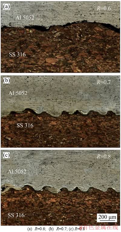
Figure 3 Microstructure of Al 5052-SS 316 explosive clad at varied loading ratios:
Smaller interfacial amplitudes seen at other interfacial spots are attributed to the lower pressure developed and lower deformation work (W) performed at the interface (0.461 MJ/m2). The deformation work depends on the kinetic energy utilization at the interface and is analytically estimated by:
 (8)
(8)
where Vw is the collision velocity; and C is the sound velocity of the flyer plate.
The interface microstructure for a loading ratio, R=0.7 (Figure 3(b)), reveals the characteristic wavy interface with formation of few intermetallic compounds on the vortices. The increase in loading ratio (R=0.7) provides a 20% additional kinetic energy utilization (0.974 MJ/m2), and hence more deformation work is performed (0.574 MJ/m2), leading to an increase in the interfacial amplitude (Figure 3(b)). For the highest loading ratio, R=0.8, interfacial waves are bigger (Figure 3(c)), due to the highest kinetic energy dissipation (1.18 MJ/m2) and the subsequent maximum deformation work performed at the interface (0.696 MJ/m2). Consequently, the temperature developed at the vicinity is higher (detailed in the next section), and supports the formation of intermetallic compounds at the interface as seen in Figure 3(c). The distinct variation in the density and thermal conductivity of participant metals inhibits the uniform distribution of thermal energy, supporting the formation of intermetallic compounds as well [25]. Formation of intermetallic compounds at higher energetic conditions is consistent with the reports of earlier researchers [26, 27].
5.2 Positioning in weldability window
The lower boundary of the weldability window was generated between welding velocity, Vw, and dynamic bend angle, ��, as ordinates and abscissa, respectively (Figure 4). The dynamic bend angle (Eq. (2)) and collision velocity, for the attempted conditions, were determined as represented in the Al-steel weldability window (Figure 4). The properties of flyer plate (Al 5052) are more influential in formulating the weldability window (Eq. (1)). The attempted experimental conditions are falling very closer to the lower boundary, results in a wavy interface to satisfy the design requirements.
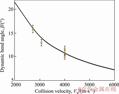
Figure 4 Weldability window for aluminum-steel explosive cladding
5.3 Numerical analysis
Figure 5 shows the various stages of Al 5052-SS 316 explosive cladding for a loading ratio of 0.7, in a two-dimensional space. The dispersion of SPH particles in explosive is hidden, for better visualizing and understanding of the various stages of collision. The detonation of the chemical explosive (Figure 5(a)) initiates the propulsion of the aluminum flyer plate towards the stainless base plate, as shown in Figure 5(b).
The shock wave emanating from the chemical explosive propagates through the flyer plate at the speed of sound, and hence the cubic structure of the lattice transforms into monoclinic, following the high deviatoric stresses [15]. Subsequently, the oblique movement of flyer plate is visible as the number of cycles increases (Figures 5(c)-(f)). Subsequent to the collision of flyer and base plates, high pressure and temperature are generated near the collision region, detailed in the subsequent sections. The pressure developed at the collision point was analytically estimated by [4]:
 (9)
(9)
where �� is the density of flyer plate; Vp is the velocity of the flyer plate. The high pressure created breaks the oxide surfaces on participant metals promoting ��surface jetting��, and causes the two virgin surfaces to be compressed together to form a clad [28]. The generated high pressure brings the atoms of participant metals closer in order to achieve a metallurgical bond, creating a successful explosive clad. Subsequent to the collision of flyer plate with the base plate, the kinetic energy available in the flyer plate was instantaneously converted into high pressure and then into thermal energy [29].
The three-dimensional contour of the process, in middle and final stages of the cycle for the different loading ratios attempted is shown in Figure 6. The SPH particle dispersion of the explosive is also seen in the middle stages of the process. As the process descends, the scattering of lower melting point aluminum (flyer plate) is also visible as reported by LIU et al [30].
5.4 Pressure contour
The pressure distribution is relatively uniform, except for the collision point and its surroundings, where a very high pressure is witnessed (Figure 7. The pressure developed in the collision point increases with the loading ratio, R. In addition, the pressure developed at the interface is higher than the dynamic strength of the participant metals, which causes a transient fluid-like state at the interface and promotes ��jetting�� phenomenon. According to Ref. [28], jet formation leads to good bonding. For a lower loading ratio (R=0.6), the maximum pressure of 1.5 GPa is witnessed at the initial stages of the collision (Figure 7(a)). However, as the loading ratio is increased to 0.7, a pressure of 2.2 GPa (Figure 7(b)) is observed in the mid section of the weld, as reported in Ref. [17]. The maximum pressure 3.6 GPa is observed in the tail end of the process (Figure 7(d)) for the highest loading ratio (R=0.8). In addition, the pressure tends to decline rapidly as the collision point shifts continuously.
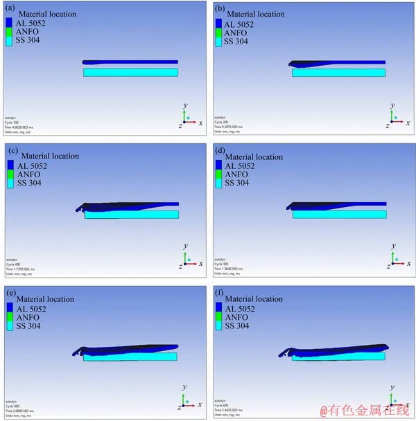
Figure 5 Stages of explosive cladding
5.5 Temperature distribution
Figure 8 exhibits the temperature distribution across the participant plates at various loading ratios during the explosive cladding process. The temperature developed at the interface for the minimum (Figure 8(a): R=0.6) and the maximum (Figure 8(d): R=0.8) loading ratio reaches 1100 and 1520 K, respectively. The lowest temperature was higher than the melting point of weaker metal (aluminum: 933 K). Further, it is observed that the increase in loading ratio enhances the interface temperature closer to the melting point of stainless steel. The increase in temperature is highly localized at the collision interface, and thereby molten layer is formed, consistent with the experimental microstructure (Figure 3).
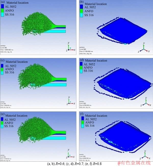
Figure 6 Explosive cladding at different loading ratios:
This localized temperature rise leads to higher cooling rates, in the order of 105-107 K/s, at the clad interface [24]. No significant increase in temperatures is observed at the regions (100 ��m) away from the interface.
5.6 Verification of numerical simulation
The experimental outcome of the attempted conditions to obtain a successful clad is consistent with the numerical simulation. The interface hardness and tensile strength of the dissimilar explosive clad, at varied loading ratios, are displayed in Figure 9. The interface exhibits higher hardness than the aluminum. The hardness value increases with loading ratio as the quantum of applied pressure increases. Similarly, the tensile strength of the dissimilar explosive clads is higher than that of the weaker parent metal (Al 5052).
The pressure developed at the collision point is closer to the analytical expression (Eq. (9)), which increases with the loading ratio. The collision velocity is determined by dividing the length of the material by the total duration of simulation and is in agreement with the experiments. The dynamic bend angle (Eq. (2)) created during the high impact collision concurs with the numerical simulation. The pressure developed at the detonation front is similar to the Gruneisen equation, confirming the judicial selection of governing equations for the explosive (Figure 7). The temperature predicted by the numerical simulation exceeds the melting point of the weaker metal as seen in the experimental results (Figure 8). The deviation between the analytical and numerical pressure developed at the interface is less than 10%. It is concluded that the numerical simulation is an effective approach to study the collision (internal) parameters influenced by the external operational parameters.
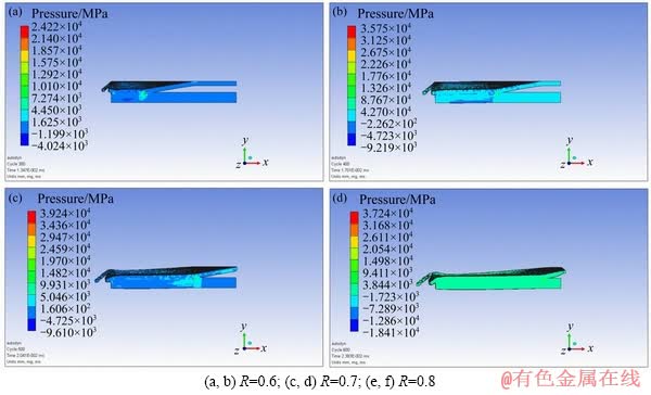
Figure 7 Pressure contours in Al 5052-SS 316 explosive cladding:
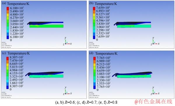
Figure 8 Temperature developed in Al 5052-SS 316 explosive cladding:
6 Conclusions
The experimental study on explosive cladding of Al 5052-SS 316 plates subjected to varied loading ratios, leads to the following salient conclusions:
1) Numerical simulation is capable of analyzing collision parameters dictated by the operational parameters.
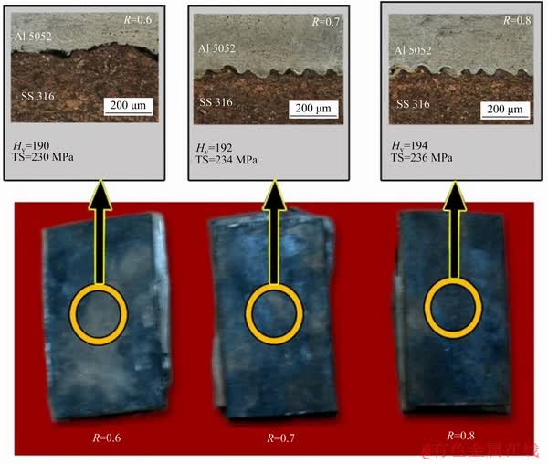
Figure 9 Explosive clad samples (Al 5052-SS 316)
2) The interfacial microstructure exhibits a smooth wavy topography with the joint strength higher than the weaker parent metal.
3) The experimental conditions located closer to the lower boundary of the weldability window produce a smooth and wavy interfacial topography.
References
[1] LU Y, MAYTON E, SONG H, KIMCHI M, ZHANG W. Dissimilar metal joining of aluminum to steel by ultrasonic plus resistance spot welding-Microstructure and mechanical properties [J]. Materials and Design, 2019, 165: 107585. DOI: 10.1016/j.matdes.2019.107585.
[2] ACEVES S M, ESPINOSA-LOZA F, ELMER J W, HUBER R. Comparison of Cu, Ti and Ta interlayer explosively fabricated aluminum to stainless steel transition joints for cryogenic pressurized hydrogen storage [J]. International Journal of Hydrogen Energy, 2015, 40(3): 1490-1503. DOI: 10.1016/j.ijhydene.2014.11.038.
[3] CORIGLIANO P, CRUPI V, GUGLIELMINO E, SILI A M. Full-field analysis of AL/FE explosive welded joints for shipbuilding applications [J]. Marine Structures, 2018, 57: 207-218. DOI: 10.1016/j.marstruc.2017.10.004.
[4] SARAVANAN S, RAGHUKANDAN K, KUMAR P. Effect of wire mesh interlayer in explosive cladding of dissimilar grade aluminum plates [J]. Journal of Central South University, 2019, 26(3): 604-611. DOI: 10.1007/ s11771-019-4031-9.
[5] CARVALHO G H S F L, GALVAO I, MENDES R, LEAL R M, LOUREIRO A. Formation of intermetallic structures at the interface of steel-to-aluminium explosive welds [J]. Materials Characterization, 2018, 142: 432-442. DOI: 10.1016/j.matchar.2018.06.005.
[6] SARAVANAN S, INOKAWA H, TOMOSHIGE R, RAGHUKANDAN K. Effect of silicon carbide particles in microstructure and mechanical properties of dissimilar aluminium explosive cladding [J]. Journal of Manufacturing Processes, 2019, 47: 32-40. DOI: 10.1016/ j.jmapro.2019.09.027.
[7] GLADKOVSKY S V, KUTENEVA S V, SERGEEV S N. Microstructure and mechanical properties of sandwich copper/steel composites produced by explosive welding [J]. Materials Characterization, 2019, 154: 294-303. DOI: 10.1016/j.matchar.2019.06.008.
[8] WANG Y, LI X, WANG X, YAN H. Fabrication of a thick copper-stainless steel clad plate for nuclear fusion equipment by explosive welding [J]. Fusion Engineering and Design, 2018, 137: 91-96. DOI: 10.1016/j.fusengdes.2018.08.017.
[9] ZENG X Y, WANG Y X, LI X Q, LI X J, ZHAO T J. Effects of gaseous media on interfacial microstructure and mechanical properties of titanium/steel explosive welded composite plate [J]. Fusion Engineering and Design, 2019, 148: 111292. DOI: 10.1016/j.fusengdes.2019.111292.
[10] ZHANG H, JIAO K X, ZHANG J L, LIU J. Experimental and numerical investigations of interface characteristics of copper/steel composite prepared by explosive welding [J]. Materials and Design, 2018, 154: 140-152. DOI: 10.1016/ j.matdes.2018.05.027.
[11] GUO X, TAO J, WANG W, LI H, WANG H C. Effects of the inner mould material on the aluminium�C316L stainless steel explosive clad pipe [J]. Materials and Design, 2013, 49: 116-122. DOI: 10.1016/j.matdes.2013.02.001.
[12] SARAVANAN S, RAGHUKANDAN K. Influence of interlayer in explosive cladding of dissimilar metals [J]. Materials and Manufacturing Processes, 2013, 28(5): 589-594. DOI: 10.1080/10426914.2012.736665.
[13] REN Bao-xiang, TAO Gang, WEN Peng, DU Chang-xing. Study on weldability window and interface morphology of steel tube and tungsten alloy rod welded by explosive welding [J]. International Journal of Refractory Metals and Hard Materials, 2019, 84: 105005. DOI: 10.1016/ j.ijrmhm.2019.105005.
[14] YANG M, SHEN Z W, CHEN D G, DENG Y X. Microstructure and mechanical properties of Al-Fe meshing bonding interfaces manufactured by explosive welding [J]. Transactions of Nonferrous Metals Society of China, 2019, 29(4): 680-691. DOI: 10.1016/S1003-6326(19)64978-2.
[15] SARAVANAN S, RAGHUKANDAN K. Energy dissipation in explosive welding of dissimilar metals [J]. Materials Science Forum, 2011, 673: 125-129. DOI: 10.4028/www.scientific.net/MSF.673.125.
[16] SATYANARAYAN, MORI A, NISHI M, HOKAMOTO K. Underwater shock wave weldability window for Sn-Cu plates [J]. Journal of Materials Processing Technology, 2019, 267: 152-158. DOI: 10.1016/j.jmatprotec.2018.11.044.
[17] LIU M B, ZHANG Z L, FENG D L. A density-adaptive SPH method with kernel gradient correction for modeling explosive welding [J]. Computational Mechanics, 2017, 60(3): 513-529. DOI: 10.1007/s00466-017-1420-5.
[18] HEUZE O. General form of the Mie�CGr��neisen equation of state [J]. Comptes Rendus Mecanique, 2012, 340(10): 679-687. DOI: 10.1016/j.crme.2012.10.044.
[19] SOMASUNDARAM S, KRISHNAMURTHY R, KAZUYUKI H. Effect of process parameters on microstructural and mechanical properties of Ti-SS 304L explosive cladding [J]. Journal of Central South University, 2017, 24(6): 1245-1251. DOI: 10.1007/s11771-017-3528-3.
[20] YANG M, MA H, SHEN Z. Study on explosive welding of Ta2 titanium to Q235 steel using colloid water as a covering for explosives [J]. Journal of Materials Research and Technology, 2019, 8(6): 5572-5580. DOI: 10.1016/j.jmrt.2019.09.025.
[21] SATYANARAYAN, TANAKA S, MORI A, HOKAMOTO K. Welding of Sn and Cu plates using controlled underwater shock wave [J]. Journal of Materials Processing Technology, 2017, 245: 300-308. DOI: 10.1016/j.jmatprotec.2017.02. 030.
[22] TAMILCHELVAN P, RAGHUKANDAN K, SARAVANAN S. Kinetic energy dissipation in Ti-SS explosive cladding with multi loading ratios [J]. IJST-Transactions of Mechanical Engineering, 2014, 38(M1): 91-96. https://www.sid.ir/en/VEWSSID/J_pdf/8542014M112.pdf.
[23] SARAVANAN S, RAGHUKANDAN K, HOKAMOTO K. Improved microstructure and mechanical properties of dissimilar explosive cladding by means of interlayer technique [J]. Archives of Civil and Mechanical Engineering, 2016, 16(4): 563-568. DOI: 10.1016/j.acme.2016.03.009.
[24] BATAEV I A, LAZURENKO D V, TANAKA S, HOKAMOTO K, BATAEV A A, GUO Y, JORGE J A M. High cooling rates and metastable phases at the interfaces of explosively welded materials [J]. Acta Materialia, 2017, 135: 277-289. DOI: 10.1016/j.actamat.2017.06.038.
[25] SARAVANAN S, RAGHUKANDAN K. Thermal kinetics in explosive cladding of dissimilar metals [J]. Science and Technology of Welding and Joining, 2012, 17(2): 99-103. DOI: 10.1179/1362171811Y.0000000080.
[26] ATHAR M H, TOLAMINEJAD B. Weldability window and the effect of interface morphology on the properties of Al/Cu/Al laminated composites fabricated by explosive welding [J]. Materials and Design, 2015, 86: 516-525. DOI: 10.1016/j.matdes.2015.07.114.
[27] KUMAR C W D, SARAVANAN S, RAGHUKANDAN K. Influence of grooved base plate on microstructure and mechanical strength of aluminum�Cstainless steel explosive cladding [J]. Transactions of the Indian Institute of Metals, 2019, 72(12): 3269-3276. DOI: 10.1007/ s12666-019- 01795-w.
[28] ZHANG Z L, LIU M B. Numerical studies on explosive welding with ANFO by using a density adaptive SPH method [J]. Journal of Manufacturing Processes, 2019, 41: 208-220. DOI: 10.1016/j.jmapro.2019.03.039.
[29] ZHOU Q, FENG J, CHEN P. Numerical and experimental studies on the explosive welding of tungsten foil to copper [J]. Materials, 2017, 10(9): 984. DOI: 10.3390/ ma10090984.
[30] LIU R, WANG W, ZHANG T, YUAN X. Numerical study of Ti/Al/Mg three-layer plates on the interface behavior in explosive welding [J]. Science and Engineering of Composite Materials, 2017, 24(6): 833-843. DOI: 10.1515/ secm-2015-0491.
(Edited by ZHENG Yu-tong)
���ĵ���
���ֱ�ը���ӵ�ʵ������ֵ�о�
ժҪ�������о��˱仯�غɱ�(ըҩ����/��������)�����ֱ�ը���ӽ�������ʡ��¶Ⱥ�ѹ����Ӱ�졣�����غɱ�R������ըײ�����ѹ�������ܵ����úͱ��ι������¶����ߵ�����ĸ��������۵�ʱ���ڽ����ṹ�е�һЩ���γ����ڲ㡣��Ansys AUTODYN�����ù⻬�ʵ����嶯��ѧ(SPH)�����¶Ⱥ�ѹ�������ӽ�����ֵģ�⣬ȷ����ը���ֽ������ӵĹ���������
�ؼ��ʣ���ը���ӣ����ֽ�������ֵģ�⣻�۽ṹ���ɺ��Դ���
Received date: 2019-08-23; Accepted date: 2020-03-07
Corresponding author: SARAVANAN S, PhD, Associate Professor; Tel: +91-9443676936; E-mail: ssvcdm@gmail.com; ORCID: 0000- 0003-2961-4420

