J. Cent. South Univ. Technol. (2010) 17: 708-714
DOI: 10.1007/s11771-010-0544-y
Electrodeposition of Ni-Co-Fe2O3 composaite coatings
MA Li(马莉)1, ZHOU Ke-chao(周科朝)1, LI Zhi-you(李志友)1, WEI Qiu-ping(魏秋平)2
1. Key State Laboratory of Powder Metallurgy, Central South University, Changsha 410083, China;
2. School of Materials Science and Engineering, Central South University, Changsha 410083, China
? Central South University Press and Springer-Verlag Berlin Heidelberg 2010
Abstract: Ni-Co-Fe2O3 composite coatings were electrodeposited using cetyltrimethylammonium bromide (CTAB)-modified Watt’s nickel bath with Fe2O3 particles dispersed in it. The effects of the plating parameters on the chemical composition, structural and morphological characteristics of the electrodeposited Ni-Co-Fe2O3 composite coatings were investigated by energy dispersive X-ray (EDS) spectroscopy, X-ray diffractometry (XRD) and scanning electron microscopy (SEM). The results reveal that Fe2O3 particles can be codeposited in the Ni-Co matrix. The codeposition of Fe2O3 particles with Ni-Co is favoured at high Fe2O3 particle concentration and medium stirring, and the deposition of Co is favoured at high concentration of CTAB. Moreover, the study of the textural perfection of the deposits reveals that the presence of particles leads to the worsening of the quality of the observed <220> preferred orientation. Composites with high concentration of embedded particles exhibit a preferred crystal orientation of <111>. The more the embedded Fe2O3 particles in the metallic matrix, the smaller the sizes of the crystallite for the composite deposits.
Key words: electrodeposition; Co-Ni alloy; Fe2O3 particles; composite coatings; cetyltrimethylammonium bromide
1 Introduction
Composites of a metallic matrix containing a dispersion of second-phase particles have attracted extensive attention from science and technology communities for decades, due to the special properties e.g., high hardness [1-2], good wear resistance [1-4], self-lubrication [5], high temperature oxidation and corrosion resistance [6-11].
Ni-based alloys are used in a wide variety of applications such as aerospace, energy generation and corrosion protection. They are especially applicable to the environment where materials are required to withstand high temperatures and oxidation conditions [12-13]. In order to further improve the high temperature and corrosion properties of the Ni- or Ni-based alloy, many electrodeposited metallic Ni and Ni-based coating incorporated with second-phase such as ceramic or metallic particles including ZrO2 [8], Al2O3 [9], Al [10] and Cr [11], were investigated.
Although the electrocodeposition process has been investigated for a long time, the mechanism of particle incorporation is not fully understood. The composition, structure and properties of the composite films are affected by several correlated parameters, such as the composition and particle concentration of the plating bath, the characteristics of the particles, temperature, pH, agitation, type of applied current, and current density.
Ni-Co alloy has a variety of merits such as good adhesion, low stress, good corrosion resistance, and good thermal stability. Thus, it is a popular choice in many industries. For the purpose of broadening the application fields of the Ni-Co alloy-based electrodeposited coatings as a potential candidate for high temperature oxidation- resistant and anticorrosive coating in the extreme environments containing water or other corrosive compounds, a method of incorporating Fe2O3 particles in electrodeposited Ni-Co alloy coating was put forward. It is expected that Fe2O3 particles can react with NiO at high temperature, producing NiFe2O4 spinel phase, which has compact structure, good thermal stability and high temperature conductivity, and greatly improve the high temperature oxidation and corrosion resistance. Ni-Co-Fe2O3 composite coatings were prepared via direct current electrodeposition technology in a Ni-Co plating bath containing Fe2O3 particles in this work. The main goal of this work was to investigate the effects of plating parameters (e.g., particle loading in bath, stirring speed and surfactant concentration) on the chemical composition, structural and morphological characteristics of electrodeposited Ni-Co-Fe2O3 composite coatings.
2 Experimental
2.1 Coatings electrodeposition
The Ni-Co-Fe2O3 composites were deposited on red copper samples with the size of 30 mm×30 mm×2 mm. The plating bath was a traditional Watt’s style containing 250 g/L NiSO4・6H2O, 45 g/L NiCl2・6H2O, 3 g/L CoSO4・7H2O, 35 g/L H3BO3 with/without the addition of cetyltrimetylammonium (CTAB). The concentration of CTAB was varied from 0 to 0.14 g/L. The morphology of Fe2O3 powders before treatment is shown in Fig.1. The average particle size of Fe2O3 powders was 1.4 μm, tested by a laser particle sizer (Zatasizer nano-ZS, Malvern). Prior to plating, Fe2O3 particles were dispersed in the electrolyte in the presence of CTAB. All the baths were rinsed and prepared using deionized water and analytical reagent grade chemicals, respectively. The bath temperature was kept at (45±3) ℃. The pH of the bath was adjusted to 4.5 using H2SO4 or ammonia. The substrates were sequentially ultrasonically cleaned in ethanol, acetone, and distilled water, each for 10 min, then activated in 1:1 (volume ratio) H2SO4 for 30 s, washed with distilled water, and finally immersed immediately in the plating bath to allow the electrodeposition of the target composite coatings. During the deposition process, the plating electrolyte was agitated with a magneton stirring. The depositing current density was 2.5 A/dm2 with a depositing time of 120 min.
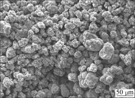
Fig.1 SEM image of Fe2O3 particles before treatment
2.2 Coatings characterization
The surface morphology of the composite electrodeposits was characterized with SEM (JSM- 5600). The composition of the electrodeposits was determined by EDS (energy dispersive X-ray spectroscope, Oxford Link ISIS 300). The structure of deposits was measured using an X-ray diffractometer (RIGAKU/MAX-3A) with Cu Kα radiation (λ=0.154 0 nm). The X-ray scan rate was 8 (?)/min and 2θ ranged from 35? to 85?. The texture coefficient was analyzed using the X-ray diffraction pattern.
3 Results and discussion
3.1 Impacts of main processing parameters on coating composition
3.1.1 Effects of Fe2O3 particles concentration
The relationship between the content of the composite coating components (Co and Fe2O3) and the concentration of Fe2O3 in the plating bath at a current density of 2.5 A/dm2 is shown in Fig.2. An overall increase trend of incorporation can be observed with increasing particles concentration in the bath. This result agrees with previous works [14-15] in the sense that particle content in the composite electrodeposits increases with respect to its increase in the bath. Codeposition mechanisms for the dispersion of the inert particles into metallic coatings have been developed for ages. Many theories have been proposed in order to explain this mechanism of composite electrodepositing course [16-18]. Among them, the mechanism proposed by GUGLIELMI [16] has been widely accepted. According to GUGLIEMI’s model, the first step is the adsorption of metal ions onto the hard particles. This step is the loose adsorption, that is, particles have loose physical adsorption onto the cathode with a high degree of metal ion coverage. In this step, a layer of adsorbed ions and solvent molecules can form screening shell to hinder the interaction between the electrode and the particles. The second step is the strong adsorption, which is believed to be assisted with the electric field, whereby, a substantially electrochemical reaction produces a strong adsorption of powders onto the electrode. In this step, the metal ions discharge at the cathode, and subsequently the particles are entrapped in the metal matrix. Hence, an increase in the concentration of Fe2O3 particles in the bath can increase the quantity of loosely adsorbed Fe2O3 particles on the cathode surface, which results in an increase in the level of incorporation of Fe2O3 particles in the coating. Furthermore, no evident differences can be observed for the Co contents of different particles concentrations in the bath, which indicates that Fe2O3 addition has no obvious effect on the Co reduction at the cathode.
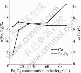
Fig.2 Change in contents (mass fraction) of embedded Fe2O3 particles and Co in composite coatings at different concentrations of Fe2O3 particles in bath
3.1.2 Effects of stirring speed
The relationship between the contents of the composite coating components (Co and Fe2O3) and stirring speed at a fixed bath Fe2O3 particle concentration of 30 g/L is shown in Fig.3. The rate of particle incorporation visibly increases until it attains a maximum and then decreases gradually with a further increase in stirring speed. Adjusting stirring speed does not change Co concentration in the deposit obviously, as shown in Fig.3, which indicates that it does not have a remarkable influence on the Co2+ reduction process. The decrease in the particle incorporation has previously been attributed to the collision effect [1]. When the number of the transferred particles is too large to be completely engulfed by the growing matrix, the free particles (e.g., neither adsorbed nor incorporated) collide with the incoming particles. This collision factor results in a decrease in the rate of incorporation. According to TIAN and CHENG [7], an increase in stirring speed would increase the degree of incorporation. However, excessive stirring may lead to a lower quantity of the particles in the metal deposit due to the vigorous hydrodynamic force in the electrolyte removing the particles from the cathode surface before they can be entrapped in the metal deposit. If the stirring speed is too low, particles in the bath may not be dispersed completely. If the stirring speed is too high, particles will not have sufficient time to be attached to the surface, and thus leading to the low particle incorporation.
3.1.3 Effects of surfactants concentration
The effects of CTAB concentration on the content of the composite coating components (Co and Fe2O3) are shown in Fig.4. From the results of Fig.4, it is interesting to note that there is no significant increase in the incorporation of Fe2O3 particles with CTAB addition; but a slight decreasing trend can be observed. Similar behavior can be observed in Ref.[15]. This can be associated with the decrease in the surface tension resulting from the surfactant addition [15, 19], which can cause changes in the cathode surface, and influence the forces that act over the particle as soon as incorporation takes place. In this case, CTAB can be adsorbed on the surfaces of the particles and the cathodes, therefore, decreasing its incorporation degree. Besides, MALFATTI et al [15] also mentioned that the surfactant adsorption on the particles surface can even change the hydrophobic behavior of the ceramic particles. The surfactants are usually adsorbed on the particle with their hydrophobic part, thus becoming the hydrophilic particle due to the surfactant layer that is adsorbed. It is necessary to consider that a hydrophilic particle, in order to incorporate, must be turned aside, avoiding the water molecules to adsorb on the particle surface. Another reason is due to a lower particle loading of 6 g/L, compared to the CTAB concentration of 0.12 g/L in the electrolyte solution. Excessive surfactant cannot disperse a low particle loading effectively, resulting in poor particle incorporation. In addition, a slight change of the particle incorporation level can be obtained at the surfactant concentration of 0.12 g/L. However, with further increase of CTAB concentration up to 0.14 g/L, a decreasing trend can be observed. These results might be due to the low particle loading and poor particle dispersion in the bath. Besides, it can be obtained from Fig.2 that the content of Co is as low as 6.5% in the absence of CTAB. And by increasing the concentration of CTAB, an increasing trend of Co content in the coatings can be observed. These can be ascribed to the fact that CTAB can promote Co2+ reduction in the cathode, which results in an increase of Co content in the
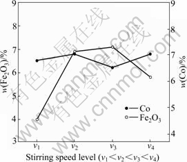
Fig.3 Change in contents (mass fraction) of embedded Fe2O3 particles and Co in composite coatings at different stirring speed levels
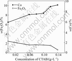
Fig.4 Change in contents (mass fraction) of embedded Fe2O3 particles and Co in composite coatings at different CTAB concentrations
coatings.
3.2 XRD patterns of Ni-Co-Fe2O3 composite coatings
The XRD patterns of the electrodeposited Ni-Co-Fe2O3 composite coatings obtained at bath loadings of 6, 30, 60 and 90 g/L Fe2O3 are shown in Fig.5. The XRD patterns confirm that the electrodeposited Ni-Co alloy coating is composed of a solid solution. It should be noticed that the diffraction peaks of Fe2O3 are not detected due to low Fe2O3 contents in the composite coatings. For the purpose of determining the preferred crystalline orientation of the deposits and evaluating the quality of this orientation, the texture coefficient (CTC,(hkl)) is used, which is defined as [20]
 ×100% (1)
where I(hkl) and I0(hkl) are the diffraction intensities of the (hkl) plane measured in the diffractogram for the deposit and the standard Ni powder sample, respectively. There are only three basic reflection lines for Ni to be considered, i.e., (111), (200) and (220), since the diffraction lines of (222) and (400) are the second-order diffraction of (111) and (200) planes, respectively. CTC,(hkl) denotes the percentage of the relative intensity of a given orientation (hkl) among the three crystallographic orientations of each sample, while a preferred orientation of the (hkl) plane is indicated by a value of CTC,(hkl)> 33.3%.
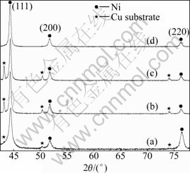
Fig.5 XRD patterns of electrodeposited Ni-Co-Fe2O3 composite coatings with different Fe2O3 concentrations: (a) 6 g/L; (b) 30 g/L; (c) 60 g/L; (d) 90 g/L
It is indicated from Fig.5 that different incorporation levels of Fe2O3 particles cause some changes in the structure of Ni-Co-Fe2O3 composite coatings. The intensity of the diffraction peaks of Ni-Co in the composite coating decreases and the peak width is enlarged with increasing the content of the particle incorporation. This is attributed to the decrease in the grain size of Ni-Co-Fe2O3 composite coating by increasing the concentration of Fe2O3 particles in the plating bath, which is proved by the average grain sizes of the coatings calculated from the diffraction peak widths (with the instrumental width eliminated) using Scherrer equation [21], namely, the growth of the electrodeposited layer is a competition process between the nucleation and crystal growth. More Fe2O3 particles provide more nucleation sites and hence retard the crystal growth; subsequently the grain size of the corresponding Ni-Co matrix in the composite coating decreases. Fig.5 also suggests a slight change in the orientation of the grains in the coatings with different incorporation levels of Fe2O3 particles in Ni-Co matrix. A careful analysis of the intensities of the diffraction lines (Table 1) shows that there is an obvious enhancement of the <111> and <100> orientations, and a clear reduction for the <110> orientation when the particle loading reaches 30 g/L. From this point of view, it should be noted that the enhancement of <111> and <100> crystalline orientations is concluded by the relative increase of (220) intensities. This effect can be attributed not only to the engulfing of Fe2O3 particles in Ni matrix, but also to their physico-chemical interaction when approaching the cathode surface. The observed textural modifications may be due to the pH changes of the bath in the presence of the dispersed Fe2O3 particles. H+ adsorption-desorption phenomenon on the particle surface takes place depending on the pH of the electrolyte that finally leads to the inhibition of the reactivity of specific chemical species, which imposes specific modes of Ni crystal growth.
3.3 SEM of Ni-Co-Fe2O3 electrodeposits
The SEM images of Ni-Co-Fe2O3 composite coating are shown in Fig.6. This coating is electrodeposited from the plating bath containing 30 g/L Fe2O3 particles, pH=4.5, at stirring speed level of 3 and 0.12 g/L CTAB addition. Spherical-like growths distributed on the surface of the deposit can be obviously observed in Fig.6(a). From the observation of the accurately prepared deposits sections, it is indicated that Fe2O3 particles are inside the Ni-Co deposits, especially embedded into the spherical-like structures (Fig.6(b)). The EDS local analysis (Fig.6(c)) demonstrates the existence of Fe2O3 particles. The investigations reveal that Ni2+ deposition is not terminated by Fe2O3 particles while it deposits at the top of Fe2O3 particles.
Fig.7 presents the SEM images of the Ni-Co-Fe2O3 composite coatings prepared at different particle loadings in the bath. It is evident from Figs.7(a), (c) and (e) that the codeposition of Fe2O3 particles into Ni-Co-Fe2O3 coating is improved with increasing particles concentration in the bath to 90 g/L. Many agglomerated Fe2O3 particles can be found from Fig.7(a). This may be due to the fact that a comparatively high CTAB concentration (0.12 g/L) cannot disperse a low particle loading of 6 g/L effectively in the bath. Agglomerated particles are too large to reach the cathode under our limited experimental conditions or absorb loosely on the cathode, resulting in low particle incorporation level in the deposit. Figs.7(c) and (d) show that Fe2O3 particles disperse uniformly and the content of particles is at a high level indicating from the plating bath containing 60 g/L Fe2O3 particles. Additionally, as the incorporation of spherical-shaped Fe2O3 increases, the grain size of Ni-Co-Fe2O3 decreases gradually as shown in Figs.7(b), (d), and (f). The incorporation of μm-sized Fe2O3 particles modifies the film growth by providing additional nucleation surfaces. The initial conversion of the large particles leads to a fine-grained film similar to the initial film on the Cu substrate surface. Subsequently, crystals grow columnar around the individual units, but they are restricted by the growing crystals of the neighboring units, resulting in finer crystals in the coatings. This result is in a good agreement with the XRD results (Fig.5). In general, the results from XRD patterns (Fig.5 and Table 1) and SEM images (Figs.7(c) and (e)) show that the codeposited particles suppress the growth of (220) plane in the Ni-Co matrix to some extent, but promote the growth of (111) and (200) planes. As mentioned previously, the electrochemical reactions lead to the deposition of metal atoms and involve generation of atomic and molecular hydrogen. Therefore, the crystallographic orientation changes since the metal’s surface energy is modified by the adsorption of H+.
Table 1 Effects of Fe2O3 concentration on full width at half maximum (FWHM) and texture coefficient of deposits
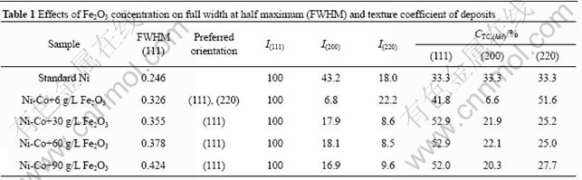
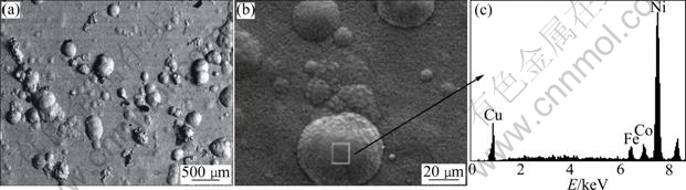
Fig.6 SEM and EDS images of Ni-Co-Fe2O3 composite coatings (Mass fraction of embedded Fe2O3 particles is 6.3%): (a) SEM image of surface; (b) Magnified map of Fig.6(a); (c) Local EDS of square in Fig.6(b)
4 Conclusions
(1) Ni-Co-Fe2O3 composite coating with mass fractions of 0.6%-10.2% Co, 0.3%-10.4% Fe2O3, and 79.3%-99.1% Ni can be electrodeposited in the CTAB-modified Watt’s Ni bath.
(2) The particle concentration increases with the increase of stirring speed firstly and then drops. As the particle concentration increases, the content of the Fe2O3 particles in the composite coatings also increases, and the maximum incorporation percentage of 10.4% (mass fraction) can be achieved at the stirring speed level of 3 and current densities of 2.5 A/dm2. Moreover, at a low particle loading of 6 g/L, there is a slight decrease in the incorporation of Fe2O3 particles with the increase of CTAB concentration. The mass fraction of Co increases approximately with the increase of CTAB concentration.
(3) The SEM results reveal that Ni-Co-Fe2O3 composite coatings consist of a spherical-like structure with Fe2O3 particles embedded. The EDS local analysis for the selected region of the Ni-Co-Fe2O3 composite coatings demonstrates the existence of the Fe2O3 particles.
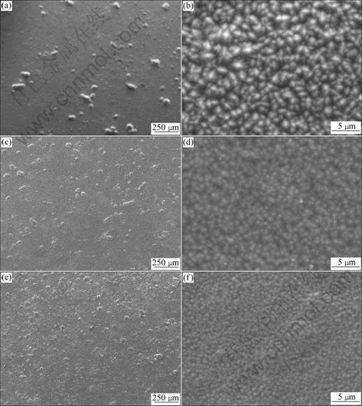
Fig.7 SEM images of Ni-Co-Fe2O3 composite coatings prepared in Watt’s bath with different concentrations of Fe2O3 particles: (a), (b) 6 g/L; (c), (d) 60 g/L; (e), (f) 90 g/L
(4) The XRD analysis shows that the presence of particles leads to the worsening of the quality of the observed <220> texture. Composites with high concentration of embedded particles exhibit a preferred crystal orientation of <111>. The more the embedded Fe2O3 particles in the metallic matrix, the smaller the crystallite sizes for composite deposits.
References
[1] GAY P A, BERCOT P, PAGETTI J. Electrodeposition and characterisation of Ag-ZrO2 electroplated coatings [J]. Surf Coat Technol, 2001, 140: 147-154.
[2] ZIMMERMAN A F, PALUMBO G, AUST K T, ERB U. Mechanical properties of nickel silicon carbide nanocomposites [J]. Mater Sci Eng A, 2002, 328: 137-146.
[3] HOU K H, GER M D, WANG L M, KE S T. The wear behaviour of electro-codeposited Ni-SiC composites [J]. Wear, 2002, 253: 994-1003.
[4] CHEN W X, TU J P, WANG L Y, GAN H Y, XU Z D, ZHANG X B. Tribological application of carbon nanotubes in a metal-based composite coating and composites [J]. Carbon, 2003, 41: 215-222.
[5] SHI L, SUN C F, ZHOU F, LIU W M. Electrodeposited nickel-cobalt composite coating containing sized Si3N4 [J]. Mater Sci Eng A, 2005, 397: 190-194.
[6] LI J, SUN Y, SUN X, QIAO J. Mechanical and corrosion-resistance performance of electrodeposited titania-nickel nanocomposite coatings [J]. Surf Coat Technol, 2005, 192: 331-335.
[7] TIAN B R, CHENG Y F. Electrolytic deposition of Ni-Co-Al2O3 composite coating on pipe steel for corrosion/erosion resistance in oil sand slurry [J]. Electrochimica Acta, 2007, 53: 511-517.
[8] TAN Cheng-yu, LIANG Ying, XIA Chang-qing, ZHENG Zi-qiao. Electrodeposition behavior and high temperature oxidation resistance of Ni/ZrO2 composite deposit [J]. Journal of Materials Protection, 2000, 33(10): 1-3. (in Chinese)
[9] WU G, LI N, ZHOU D R, MITSUO K. Microstructure and properties of Co-Ni-Al2O3 composite coatings at the high temperature [J]. Acta Materiae Composite Sinica, 2004, 21(2): 8-13. (in Chinese)
[10] ZHOU Y, PENG X, WANG F. Oxidation of a novel electrodeposited Ni-Al nanocomposite film at 1 050 ℃ [J]. Scripta Materialia, 2004, 50: 1429-1433.
[11] ZHANG Y, PENG X, WANG F. Development and oxidation at 800 ℃ of a novel electrodeposited Ni-Cr nanocomposite film [J]. Materials Letters, 2004, 58: 1134-1138.
[12] XU Li-jian, GONG Zhu-qing, TANG Jian-xin, HE Quan-guo, HE Nong-yue, DU Jing-jing. Ni-Cr alloy electrodepositing technology on Fe substrate and coating performance [J]. J Cent South Univ Technol, 2007, 14(2): 181-185.
[13] YANG Yu-fang, GONG Zhu-qing, DENG Li-yuan, LUO Bei-ping, MA Yu-tian, YANG Zhen-hui. Electrodeposition of Ni-Cr alloy on aluminum substrate [J]. J Cent South Univ Technol, 2006, 13(3): 219-224.
[14] THIEMIG D, BUND A. Characterization of electrodeposited Ni-TiO2 nanocomposite coatings [J]. Sur Coat Technol, 2008, 202: 2976-2984.
[15] MALFATTI C F, VEIT H M, MENEZES T L, FERREIRA J Z, RODRIGUES J S, BONONO J P. The surfactant addition effect in the elaboration of electrodepositated NiP-SiC composite coatings [J]. Sur Coat Technol, 2007, 201: 6318-6324.
[16] GUGLIELMI N. Kinetics of the deposition of inert particles from electrolytic baths [J]. J Electrochem Soc, 1972, 119: 1009-1012.
[17] WANG Sheng-chang, WEI Wen-cheng. Kinetics of electroplating process of sized ceramic particle/Ni composite [J]. Mater Chem Phys, 2003, 78: 574-580.
[18] CELIS J P, ROSS J R, BUELENS C. A mathematical model for the electrolytic codeposition of particles with a metallic matrix [J]. J Electrochem Soc, 1987, 134: 1402-1408.
[19] TERZIEVA V, FRANSAER J, CELIS J P. Codeposition of hydrophilic and hydrophobic silica with copper from acid copper sulfate bath [J]. J Electrochem Soc, 2000, 147: 198-202.
[20] CHEN Li, WANG Li-ping, ZENG Zhi-xiang, XU Tao. Influence of pulse frequency on the microstructure and wear resistance of electrodeposited Ni-Al2O3 composite coatings [J]. Surf Coat Technol, 2007, 201: 599-605.
[21] GULLITY B D. Elements of X-ray diffraction [M]. 2nd ed. London: Addison Wesley Publishing, 1978: 102.
Foundation item: Project(2005CB623703) supported by the National Key Basic Research Program of China; Project(50474051) supported by the National Natural Science Foundation of China; Project(CX2009B032) supported by Innovation Foundation for Postgraduate of Hunan Province of China; Project(ZKJ2009024) supported by the Precious Apparatus Open Share Foundation of Central South University, China; Project(2009ybfz02) supported by Excellent Doctor Support Fund of Central South University, China
Received date: 2009-10-29; Accepted date: 2010-03-10
Corresponding author: ZHOU Ke-chao, Professor; Tel: +86-731-88836264; E-mail: zhoukc2@web-mail.csu.edu.cn
(Edited by CHEN Wei-ping)

