
Microstructure of a two-phase titanium alloy by
rapid solidification technique
LIU Xing-xing(刘星星)1, 2, LONG Ling(龙玲)1, 2, YAN Biao(严彪)1, 2,
TANG Ren-jian(唐人剑)1, 2, ZOU Hong-liu(邹洪流)1, 2
1. Shanghai Key Labortory of D&A for Metal-Functional Materials, Shanghai 200092, China;
2. School of Materials Science and Engineering, Tongji University, Shanghai 200092, China
Received 15 July 2007; accepted 10 September 2007
Abstract: Ribbons of the two-phase titanium alloy were fabricated by single-roller rapid solidification technique, and aged at high temperature. The microstructure of ribbon samples were characterized with X-ray diffractometer (XRD) and environmental scanning electron microscope (ESEM). The microstructures of the alloy are composed of α phase and supersaturated β phase, and X-ray diffraction results show that all peaks of the α and β phases shift slightly to smaller angles, which can be explained by the disordering growth pattern caused by the rapid solidification process. After aging at 960 ℃ in vacuum, the ribbon is composed of homogeneous α phase and β phase.
Key words: single-roller rapid solidification; two-phase titanium alloy; aging
1 Introduction
Titanium and titanium alloys are increasingly used in many industries due to their very good mechanical properties as well as excellent corrosion and erosion resistance.
But currently many problems still exist during the process of fabricating titanium alloy ingot and semiproduct:
1) Large-diameter ingots have coarse-grained structures. The characteristics of the structures of titanium ingots are related to two specific factors of the conventional melting technology (self-consumption electrode vacuum arc melting in a closed crystallization container). The two factors are the distinct overheating of the alloy liquid and the relative low rates of crystallization and recrystallization during the cooling process[1]. Transformation of this structure into a fine-grained requires many process operations and consumption of a large amount of energy, labor and metal.
2) The consumption of a large amount of metal, labor and energy results in the high prices of titanium and its alloys, which therefore limits their wide use. Using rapid solidification technique as an alternative method to fabricate titanium alloy can improve the present production status effectively, which can be a possible way to solve the above mentioned problems[2].
Many researchers have studied the fabrication of γ-TiAl alloy via rapid solidification technique[3-8], but few of them concern the rapid solidification of tow-phase(α+β) titanium alloy. In this work, thin ribbons of the TC6 alloy were fabricated using single-roller by rapid solidification technique (RS), and its feasibility was studied.
2 Experimental
The TC6 ingot (Ti-6Al-2.5Mo-2Cr-0.3Si-0.5Fe) with 31 mm in diameter was used as the raw material. The process resulted in incontinuous ribbons of 15 mm wide and 100 μm thick. The as cast ingot was melted at 1 700 ℃ using induction heating. In a quartz tube small orifice was used as its base and a CaO crucible inside to avoid titanium reacting with the quartz tube at high temperature. The molten alloy was ejected onto the rapidly rotating copper wheel with estimated cooling rate of 105 K/s, at argon gas pressure of 1.4 ×10⁵ Pa. Fig.1 shows the sketch of the single roller rapid solidification technique. Then the ribbons were aged at 960 ℃ for 2 h in vacuum to observe the microstructures. The compositions of the samples were measured using the RBS technique (with 1.5 MeV, HeC beam). The ribbon was characterized by X-ray diffractometer using D/max 2550 with Cu Kα radiation (λ=15.405 6 nm), Microstructure was studied using a Philips XL-30 environmental scanning electron microscope (ESEM), and microhardness were measured with 631-type microhardness tester.
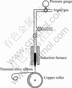
Fig.1 Sketch of single-roller rapid solidification technique
3 Results and discussion
3.1 Macroscopical morphology and chemical composition of alloy ribbons
Ribbons of about 15 mm in width and about 100 μm in thickness were obtained using the single roller melt spinning technique, as shown in Fig.2. The length of the ribbon can reflect the plasticity of the material in some extent at room temperature. The short length of the as-quenched ribbons with 10 cm indicates the poor plasticity of the ribbons, which benefits the further milling.
Fig.3 shows the XRD spectrum of the as-quenched ribbons. The comparison results of the compositions of the as-quenched TC6 ribbons and the original ingots obtained by ESEM spectrum analysis are given in Table 1. It can be seen from Table 1 that the variations of the contents of Al, Cr, Mo of the as-quenched TC6 alloy ribbons are in the allowed range, while the contents of impurities of O, H increase evidently. This may be explained by the precipitation of hydride during the rapid cooling process, which results in the sharp descent of plasticity and brittleness of the ribbons.

Fig.2 Metallography of as-quenched TC6 alloy ribbon obtained using single roller melt spinning technique

Fig.3 EDS spectrum of as-quenched ribbons
3.2 XRD results and analysis
Fig.4 shows the X-ray diffraction patterns of the TC6 alloy ingot and the as-quenched ribbon sample. By comparison, it can be seen that there is no new phase in the as-quenched ribbons. Most of β phase are remained due to not being able to transform in time during the rapid solidification process from high temperature, thus the peak intensity of the β phase only decreases slightly. During the transformation process, partial α phase dissolves in the boundaries of β phase, which causes the diffraction peaks of the α phase in the small angle region decline evidently. Furthermore, no diffraction peak of Ti5Si3 compound is detected in the diffraction pattern[9], which means the CaO crucible can effectively avoid the pollution of Si from the quartz tube during the melting process. Table 2 lists the diversifications of the lattice plane spacing of α phase in ingots and as-quenched ribbons of TC6 alloy. It can be seen from Table 2 that there is distinct increase of the lattice plane spacing of α phase in as-quenched ribbons, which may result from the distortion of the crystal lattice caused by large-size alloy elements dissolved in the Ti crystals.
Table 1 Comparison of chemical compositions of original ingots and as-quenched ribbons


Fig.4 X-ray diffraction patterns of TC6 samples: (a) ingot; (b) as-quenched ribbon
Table 2 Diversifications of lattice plane spacing of α phase in ingots and as-quenched ribbons of TC6 alloy
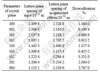
Fig.5 shows the size―strain plot obtained from the X-ray diffraction results of the ribbon by Williamson- Hall method[10]. By calculation, the grain size of the ribbon is about 24 nm, and the lattice strain is 0.45% after rapid solidification process, which provides important basis for latter measurement of microhardness.

Fig.5 Williamson-Hall curves of as-quenched ribbon of TC6 titanium alloy with crystallite size of 24 nm and strain of 0.45%
3.3 Mechanical properties of ribbons
Measured by 631-type microhardness tester, the microhardness of HV 357 and HV 510 of the ingot and as-quenched ribbon of titanium alloy was obtained. The microhardness of as-quenched titanium alloy ribbon is greatly improved, due to the fine-grained structure ranging from 33 nm to 24 nm obtained by rapid solidification technique. According to Hall-Petch[11] relationship, the yield strength or microhardness of material increases with the decrease of the grain size. The experimental result proves the validity of Hall-Petch relationship, and indicates that rapid solidification can be very effective in improving the mechanical properties of the alloy by affecting the solid structure.
3.4 Heat treatment and aging of as-quenched TC6 alloy ribbons
Fig.6 shows the SEM image of the ribbon sample aged at high temperature. After aging at high temperature in vacuum, it can be clearly observed that the α phase precipitates from the boundaries of the β phase, and grows into the inner of the β phase grains. This is mainly because of the high congregation of impurities and all kinds of defects (cavities, interstitial solutes, dislocations, etc) in the boundaries, which lowers the free energy needed for the formation of α phase nucleus to half of the free energy needed in the inner of the β phase by calculation. This therefore results in the first precipitation of α phase from the boundaries of the β phase. The flake α phases are mainly the transformation products of the residual β phases.
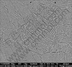
Fig.6 SEM image of ribbon sample aged at high temperature
Besides, from the aspects of crystallography, the precipitated phase usually remains some tropism relations with the residual phase, to keep the minimum interfacial energy, and the transformation proceeds in a line of least resistance, which results in the formation of flake-like α phase. For the (α+β) two-phase titanium alloy, as long as the cooling process from high temperature to low temperature exists, there will be the transformation of β phase, thus the formation of flake α phase.
4 Conclusions
1) The two-phase titanium alloy ribbons are obtained by rapid solidification technique, with the microstructure composed of α phase and supersaturated β phase.
2) All the peaks of the α and β phase shift slightly to smaller angles. This can be explained by the disordering growth pattern caused by the rapid solidification process.
3) The α phase precipitates from the boundaries of the β phase after being aged at 960 ℃ in vacuum.
4) The as-quenched ribbons indicates a poor plasticity of the ribbons, which benefits the further milling to get high quality alloy powder.
References
[1] ZHANG Guo-cai. The rolling and forging technique of large- diameter titanium ingots[J]. Titanium Industry Progress, 1995, 2: 22-23.
[2] Anoshkin N F, Demchenkov G G. Material science and technological aspects of rapidly solidified titanium alloy production[J]. Materials Science and Engineering, 1998, 243(1/2): 263-268.
[3] LIU Yong-chang, LAN Feng, YANG Gen-cang, ZHOU Yao-he. Microstructural evolution of rapidly solidified Ti-Al peritectic alloy[J]. Journal of Crystal Growth,2004, 271(1/2): 313-318.
[4] Liu Y C, Yang G C, Guo X F, Huang J, Zhou Y H. Coupled growth behavior in the rapidly solidified Ti-Al peritectic alloys[J]. Journal of Crystal Growth,2001, 3(222): 645-654.
[5] SU Yan-qing, GUO Jing-jie, JIA Jun, LIU Gui-zhong, LIU Yuan. Composition control of a TiAl melt during the induction skull melting (ISM) process[J]. Journal of Alloys and Compounds, 2002, 334(1/2): 264-266.
[6] SU Yan-qing, LIU Chang, LI Xin-zhong, GUO Jing-jie, LI Bang-sheng, JIA Jun, FU Heng-zhi. Microstructure selection during the directionally peritectic solidification of Ti-Al binary system[J]. Intermetallics, 2005, 13(3/4): 267-274.
[7] LIU Yong-chang, LAN Feng, YANG Gen-cang, ZHOU Yao-he. Microstructural evolution of rapidly solidified Ti-Al peritectic alloy[J]. Journal of Crystal Growth, 2004, 271(1/2): 313-318.
[8] GUO Jing-jie, LI Xin-zhong, SU Yan-qing, WU Shi-ping, LI Bang-sheng, FU Heng-zhi. Phase-field simulation of structure evolution at high growth velocities during directional solidification of Ti55Al45 alloy[J]. Intermetallics, 2005, 13(3/4): 275-279.
[9] MA Xue-zhu. The study of microstructure and thermal stability of TiAl base alloy by rapid solidification[D]. Harbin: Harbin Institute of Technology, 2001: 8. (in Chinese)
[10] Mukhopadhyay N K, et al. J Alloys Compd[EB/OL]. doi: 10.1016/j.jallcom.2007-03-043.
[11] Saada G. Hall-Petch revisited[J]. Materials Science and Engineering, 2005, 400/401: 146-149.
Foundation item: Projects(0552nm028; 04DZ05616) supported by Shanghai Science and Technology Committee
Corresponding author: YAN Biao; Tel: +86-21-65981178; E-mail: yanbiao@vip.sina.com
(Edited by CHEN Can-hua)

