
Influences of material parameters on deep drawing of thin-walled hemispheric surface part
GAO En-zhi(高恩志), LI Hong-wei(李宏伟), KOU Hong-chao(寇宏超),
CHANG Hui(常 辉), LI Jin-shan(李金山), ZHOU Lian(周 廉)
State Key Laboratory of Solidification Processing, Northwestern Polytechnical University, Xi’an 710072, China
Received 25 July 2008; accepted 21 November 2008
Abstract: During deep drawing process, the material parameters of blank have a significant effect on the quality of the drawn part and the determination of process parameters. Here, a 3D finite element model is developed for the deep drawing process of a thin-walled hemispheric surface part. Then the influences of material parameters including hardening exponent n, yield stress σs and elastic modulus E on the process are investigated by simulation. The results show that the effects of n and σs on punch force, thickness variation and equivalent strain are more notable. The maximum equivalent plastic strain occurs outside the die corner. However, when the value of n is 0.03 or σs is smaller than 120 MPa, higher equivalent plastic strain occurs at ball top.
Key words: deep drawing; material parameters; hemispheric surface part; numerical simulation
1 Introduction
Nowadays, the deep drawing process is used in the modern industry extensively. During this process, the material properties of the blank have a significant effect not only on the quality of formed part but also on the determination of process parameters. So, it is important to research the influence of material parameters on deep drawing process.
Deep drawing is a high order non-linear problem in numerical modeling. Until now, many researches on this process have been carried out by FEM simulation[1-8]. The simulation of the deep drawing of square and cylindrical cups by using the explicit non-linear finite-element code DYNA-3D was reported by MAMALIS et al[9-10]. In their work, to verify the effect of the materials and forming characteristics on the forming behavior of deep-drawn cups, an extensive simulation work was carried out. However, only elastic modulus E and density ρ were considered. XIE et al[11] did some simulations on the stamping process of a typical sheet metal part. The results show that the thickness distribution and forming limit diagram(FLD) are sensitive to material parameters n (hardening exponent) and r (anisotropic parameter).It is helpful to selecting a material for a certain forming process. Additionally, the effects of material parameters (strength factor K, hardening exponent n and anisotropic parameter r) on the formability of deep drawing of aluminum alloy sheets were mainly discussed by LI et al[12] and the optional parameters were identified. The deep drawing of a typical auto panel part was simulated by BAO et al[13], in which the effect of three very important material parameters (yield stress, hardening exponent and anisotropic parameter) on the stamping formability was investigated. The results that have been explained rationally can be served as a basis for choosing material.
The deep drawing process of square or cylindrical auto panel part was investigated. However, the effect of material parameters on the deep drawing of thin-walled hemispheric surface part has less been analyzed. Hemispheric surface parts are the bases for researching the various open type parts, as their complex forming, including expanding and deep drawing, is different from the normal deep drawing.So, in this work, the deep drawing of a thin-walled hemispheric surface part is simulated based on a self-developed 3D finite element (FE) model. The influences of material parameters including hardening exponent n, yield stress σs and elastic modulus E on the punch force, thickness variation and equivalent plastic strain are investigated by using 3D-FE numerical simulation.
2 Modeling of deep drawing process
A 3D-FE model is developed for the deep drawing simulation of a thin-walled hemispheric surface part, as shown in Fig.1.
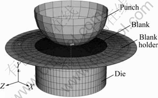
Fig.1 Finite element model used in simulation
In this model, a 4-node shell element is utilized, and a surface-to-surface contact model is adopted, in which the coulomb friction law with a friction coefficient of 0.15 is concluded. Three contact pairs as punch-blank, die-blank and blank holder-blank are created. A constant uniform pressure is applied on the blank holder in Y-direction, while the freedom of the blank holder in Y-direction is unfastened. Thus, the constant pressure may be treated as the blank holder force. The punch, die and blank holder in this model are considered as rigid bodies. Blank in the model is assumed to be isotropically elasto-plastic, and its constitutive equation is as follows[14-15]:
σ=σs(1+Kε)n (1)
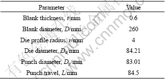
where σ is the true stress and ε is the true strain. In Eq.(1), yield stress σs and hardening exponent n are 231.6 MPa and 0.065 3, respectively. The material properties of the blank are mainly hardening exponent n, yield stress σs and elastic modulus E, so changing any one of them will obtain various suppositional materials with different material properties. The geometry parameters used in the model are listed in Table 1. The selection of materials of blank and the determination of forming parameters are not random. According to the empirical formula and previous numerical simulations, the calculation conditions used in this study are determined as follows.
Fixing unit blank holder force(BHF) at 0.8 MPa, select E=40, 69, 100, 130, 160, 220 GPa, but retain other parameters as listed in Table 1 unchanged, then six valid 3D-FE models of deep drawing have been developed.
Select σs=70, 120, 180, 231.6, 350, 450 MPa, but retain other parameters as listed in Table 1 unchanged, then six valid 3D-FE models of deep drawing have been developed.
Table 1 Tool and material geometry parameters used in model
Select n=0.03, 0.0653, 0.1, 0.2, 0.3, 0.4, but retain other parameters as listed in Table 1, then six valid 3D-FE models of deep drawing have been developed.
3 Results and discussion
3.1 Equivalent plastic strain
During deep drawing process, metal flow law of drawn part can be known through the analysis of equivalent plastic strain nephogram. Fig.2 shows the influences of material parameters on the equivalent plastic strain (identified by the symbol of PEEQ in ABAQ US environment) along the meridian direction of the drawn surface part. It can be seen that when E increases but n or σs decreases, the equivalent plastic strain increases, and generally, higher equivalent plastic strain occurs at wall region outside the die corner, because this area is the potentially dangerous location for a crack. But, when the value of n or σs continuously reduces, higher equivalent plastic strain occurs at ball top. So, it is identified as the dangerous area for potential cracks. Figs.2(b) and (c) show equivalent plastic strain nephogram and the final shape of drawn part in several particular cases. The maximum equivalent plastic strain occurs near the wall region outside the die radius. Wrinkle is observed at this region and flange portion of the part at case of σs=450 MPa or n=0.3. When the hardening exponent n is decreased to 0.03 or yield stress σs is decreased to 70 MPa, the equivalent plastic strain increases suddenly near the ball top, indicating that tearing of the material takes place as shown in Figs.2(b) and (c).
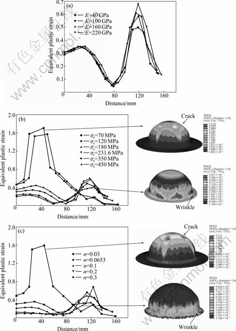
Fig.2 Influences of material parameters on equivalent plastic strain of drawn part: (a) E; (b) σs; (c) n
3.2 Punch force
During deep drawing process, punch force evolution law can be represented from the curve of punch force versus displacement, and it can provide a guide for selecting proper press machine. Fig.3 shows the influences of material parameters on punch force in the deep drawing process. It can be seen that when E, σs or n increases, higher punch force occurs, and the influences of σs and n on punch force are more notable. In Fig.3(c), the punch force varies depending on hardening exponent n applied in the simulation. The higher the hardening exponent n is, the larger the punch force is required, but an excessively high value of n (i.e. n=0.3) results in wrinkle. As the wrinkle grows and develops, the punch force required becomes erratic.
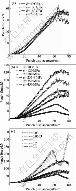
Fig.3 Influences of material parameters on punch force: (a) E; (b) σs; (c) n
3.3 Thickness variation
Thickness is one of the major quality characteristics in sheet metal part formed. Thickness is unevenly distributed in the part after deep drawing generally, with the minimum thickness at the region of punch radius and outside the die corner, and the maximum thickness at the flange area. Existence of thickness variation during the production may cause failure in the part. The main objective is to reduce thickness variation in the deep drawn part, i.e. to minimize the value of thinning and thickening. Fig.4 shows the influence of material parameters on maximum thinning and maximum thickening of the production. From Fig.4, it can be seen that when E decreases but n or σs increases, the maximum thinning decreases and depends obviously on σs and n, then E. When E increases but n or σs decreases, the maximum thickening decreases and the influences of n are notable. The influence of E on thickness variation is indistinctive.
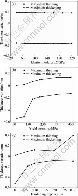
Fig.4 Influences of material parameters on thickness variation of part: (a) E; (b) σs; (c) n
4 Experimental works
The experiments are conducted on a 500 t hydraulic press. Hemispherical dies are designed and fabricated. Test blanks of 08AL steel and commercially pure (CP) titanium are adopted. The mechanical properties of the blanks are listed in Table 2. It is seen that yield strength and hardening exponent of CP titanium are smaller than those of 08AL steel. The fully drawn parts for lower BHF are shown in Fig.5. It is found that wrinkles occur at flange and side wall region of 08AL steel drawn part, while they do not occur at CP titanium part. The results indicate that the larger the σs or n is, the larger the BHF is required, i.e. the CP titanium part is easier to form than 08AL steel. So, we can say experimental observations are in agreement with the FE simulation.
Table 2 Mechanical properties of CP titanium and 08AL steel
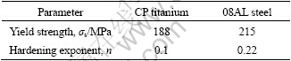
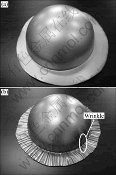
Fig.5 Views of fully formed parts: (a) CP titanium part; (b) 08AL steel part
These results may provide some guidelines for selecting the materials of blank and determining the forming parameters according to the change of materials parameters.
5 Conclusions
1) When E increases but σs or n decreases, the equivalent plastic strain increases, and generally, the maximum equivalent plastic strain occurs at wall region outside the die corner. But when the value of n decreases to 0.03 or σs is smaller than 120 MPa, higher equivalent plastic strain occurs at ball top.
2) When n, E or σs increases, higher punch force occurs, and the influences of n and σs on punch force are more notable.
3) When E decreases but n or σs increases, the maximum thinning decreases and depends mainly on n and σs, then E. When E increases but n or σs decreases, the maximum thickening decreases and the influences of n are notable.
References
[1] PADMANABHAN R, OLIVEIRA M C, ALVES J L, MENEZES L F. Influence of process parameters on the deep drawing of stainless steel [J]. Finite Elements in Analysis and Design, 2007, 43: 1062-1067.
[2] PADMANABHAN R, OLIVEIRA M C, ALVES J L, MENEZES L F. Numerical simulation and analysis on the deep drawing of LPG bottles [J]. Journal of Materials Processing Technology, 2008, 200: 416-423.
[3] FAN J P, TANG C Y, TSUI C P, CHAN L C, LEE T C. 3D finite element simulation of deep drawing with damage development [J]. International Journal of Machine Tools and Manufacture, 2006, 46: 1035-1044.
[4] GARCIA C, CELENTANO D, FLORES F, PONTHOT J P. Numerical modeling and experimental validation of steel deep drawing processes (Part I): Material characterization [J]. Journal of Materials Processing Technology, 2006, 172: 451-460.
[5] GARCIA C, CELENTANO D, FLORES F, PONTHOT J P, OLIVA O. Numerical modeling and experimental validation of steel deep drawing processes (Part II): Applications [J]. Journal of Materials Processing Technology, 2006, 172: 461-471.
[6] YOSHIHARA S, MANABE K I, NISHIMURA H. Effect of blank holder force control in deep-drawing process of magnesium alloy sheet [J]. Journal of Materials Processing Technology, 2005, 170: 579-585.
[7] CHEN Jun, SHI Xiao-xiang, RUAN Xue-yu. Numerical simulation-driven optimization of sheet metal drawing part shape [J]. Trans Nonferrous Met Soc China, 2003, 13(4): 845-848.
[8] YANG Jian-hua, CHEN Jun, HE Dan-nong, RUAN Xue-yu. Numerical simulation of two-stage deep drawing of complex-shaped parts [J]. Trans Nonferrous Met Soc China, 2003, 13(4): 839-844.
[9] MAMALIS A G, MANOLAKOS D E, BALDOUKAS A K. Simulation of sheet metal forming using explicit finite element techniques: Effect of material and forming characteristics (Part 1): Deep-drawing of cylindrical cups [J]. Journal of Materials Processing Technology, 1997, 72: 48-60.
[10] MAMALIS A G, MANOLAKOS D E, BALDOUKAS A K. Simulation of sheet metal forming using explicit finite element techniques: Effect of material and forming characteristics (Part 2): Deep-drawing of square cup [J]. Journal of Materials Processing Technology, 1997, 72: 110-116.
[11] XIE Hou-xun, ZHANG Min-zhong, JIA Hai-bin. Study on sensitivity of material constitutive parameter [J]. Metal Forming Technology, 2003, 21(2): 16-18. (in Chinese)
[12] LI Di, BI Xin-wen, LI Guang-li. Parameter sensitivity of stamping forming of aluminum alloy sheets used in automobile cover [J]. Journal of Shandong University of Technology, 2004, 18(3): 27-31. (in Chinese)
[13] BAO Xiang-jun, JIANG Hong-fan, HE Dan-nong, LI Cong-xin. Numerical simulation of the influence of material parameters on auto body panel stamping formability [J]. Materials for Mechanical Engineering, 2001, 25(7): 15-17. (in Chinese)
[14] KIM N, MACHIDA S, KOBAYASHI S. Ring rolling process simulation by the three dimensional finite element method [J]. International Journal of Machine Tools and Manufacture, 1990, 30: 569-577.
[15] YANG He, GUO Liang-gang, ZHAN Mei, SUN Zhi-chao. Research on the influence of material properties on cold ring rolling processes by 3D-FE numerical simulation [J]. Journal of Materials Processing Technology, 2006, 177: 634-638.
Foundation item: Project(2007CB613802) supported by the National Basic Research Program of China; Project(50805121) supported by the National Natural Science Foundation of China
Corresponding author: LI Hong-wei; Tel: +86-29-88491764; E-mail: lihongwei@nwpu.edu.cn
DOI: 10.1016/S1003-6326(08)60291-5
(Edited by YANG Bing)

