J. Cent. South Univ. Technol. (2009) 16: 0495-0502
DOI: 10.1007/s11771-009-0083-6

Nonlinear behavior of concrete beams with hybrid FRP and
stainless steel reinforcements
FANG Zhi(方 志)1, GONG Chang(龚 畅)1, YANG Jian(杨 剑)2, CAMPBELL T I3
(1. School of Civil Engineering, Hunan University, Changsha 410082, China;
2. School of Civil and Architectural Engineering, Central South University, Changsha 410075, China;
3. Department of Civil Engineering, Queen’s University, Ontario K7L3N6, Canada)
Abstract: The full-range behavior of partially bonded, together with partially prestressed concrete beams containing fiber reinforced polymer (FRP) tendons and stainless steel reinforcing bars was simulated using a simplified theoretical model. The model assumes that a section in the beam has a trilinear moment―curvature relationship characterized by three particular points, initial cracking of concrete, yielding of non-prestressed steel, and crushing of concrete or rupturing of prestressing tendons. Predictions from the model were compared with the limited available test data, and a reasonable agreement was obtained. A detailed parametric study of the behavior of the prestressed concrete beams with hybrid FRP and stainless steel reinforcements was conducted. It can be concluded that the deformability of the beam can be enhanced by increasing the ultimate compressive strain of concrete, unbonded length of tendon, percentage of compressive reinforcement and partial prestress ratio, and decreasing the effective prestress in tendons, and increasing in ultimate compressive strain of concrete is the most efficient one. The deformability of the beam is almost directly proportional to the concrete ultimate strain provided the failure mode is concrete crushing, even though the concrete ultimate strain has less influence on the load-carrying capacity.
Key words: beam; fiber reinforced polymer (FRP); stainless steel; prestress; deformability; reinforcement
1 Introduction
Interest in the use of fiber reinforced polymer (FRP) tendons in lieu of steel bars of prestressed concrete structures increases due to the high-strength, light-mass and corrosion-free properties of such materials [1]. The research relating to FRP prestressing, including static and fatigue testing of beams and half-scale bridges etc, has been conducted by individual investigators at many universities and institutes [2-6].
FRP materials behave differently from steel reinforcement in that they exhibit linear elastic behavior up to failure. Therefore, final failure of FRP prestressing systems may be caused by tendons rupture, which is brittle and sudden without warning in the form of notable deformations. It is better technique to use partially bonded tendons instead of fully bonded tendons in beams in order to make FRP-prestressed concrete beams have a high rotation capacity, a high load capacity and a high fatigue-resistant capacity [4-5]. Stainless steel may be used as the non-prestressed reinforcement in FRP partially prestressed concrete beams for the sake of a totally non-corrosive reinforcement system.
LEE and BURGOYNE [7] studied fully prestressed concrete beams with intermittently bonded and adhesive-bonded FRP tendons. Fully bonded and fully unbonded partially prestressed concrete beams with FRP tendons were tested and analyzed by NAAMAN et al [8], KATO and HAYASHIDA [9]. Experimental studies were conducted on partially bonded, partially prestressed concrete beams with FRP tendons, and FRP or steel reinforcements by FANG and YANG [10]. A theoretical model to simulate the behavior of a partially bonded, partially prestressed concrete beam at failure was developed by CAMPBELL et al [11]. Little, if any, research work has been reported on the full range analysis of partially bonded, partially prestressed concrete beams with hybrid FRP tendons and stainless steel reinforcements.
Therefore, the overall behavior of partially prestressed, partially bonded concrete beams utilizing combined FRP and stainless steel reinforcements was studied in this work using a simplified model.
2 Moment―curvature relationship of section
2.1 Basic assumptions
The following assumptions are used in determining the moment―curvature relationship of a section.
(1) The moment―curvature relationship is tri-linear,
as shown in Fig.1, which has characteristic points, corresponding to initial prestressing, concrete cracking, and yielding of nonprestressed reforcement and ultimate conditions. In Fig.1, Mc, Ms and Mu are the moments at concrete cracking, tensile steel yielding and ultimate, respectively; φ0, φc, φs and φu are the section curvatures at pretensioning, concrete cracking, tensile steel yielding and ultimate, respectively; EI1, EI2 and EI3 are tangent stiffnesses of the section during pre-cracking, post-cracking and post-yielding, respectively.
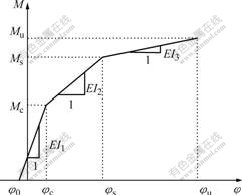
Fig.1 Idealized moment―curvature relationship of section
(2) The stress―strain curve for concrete in compression consists of a parabolic curve and a straight line [12]. The tensile strength of concrete is neglected after cracking.
(3) The stress―strain relationship for FRP tendons is linearly elastic, and that of stainless steel reinforcing bar is a bi-linear line with elastic and elasto-plastic part, respectively [12].
(4) The unbonded tendon is free to slide relative to the concrete, and therefore there is an even strain distribution along its entire unbonded length.
(5) The assumption that a plane section before deforming remains plane after deforming (Bernoulli-Euler’s assumption) is satisfied for the concrete, fully bonded tendons and longitudinal reinforcements [13]. The strain increment in the concrete at the level of tendon varies in the same manner as the moment diagram as shown in Fig.2. This assumption is exact for a straight tendon profile parallel to the longitudinal axis of the beam provided the system behaves in an elastic manner. Herein its effectiveness is extended beyond concrete cracking, and the resulting error is found to be acceptable on the basis of the analytical results presented [13].
2.2 Characteristic points on moment―curvature relationship
The moment―curvature relationship of a bonded section can be determined easily. The basic principles

Fig.2 Load configuration, moment diagram and strain increment in concrete at level of tendon: (a) Load configuration; (b) Moment diagram; (c) Strain increment in concrete
used to determine the moment―curvature relationship of an unbonded section are similar to those in a bonded section, except that in the determination of strain in an unbonded tendon. The concept of compatibility of deformation in the concrete and tendon over its entire unbonded length, rather than that at a section, must be used. This is due to the relative slip that occurs between the unbonded tendon and the surrounding concrete. Consequently, the strain in the unbonded tendon is related not only to the properties of the section, as in a bonded beam, but also to the properties of the whole beam, such as unbonded length of the tendon, boundary conditions and load configuration. Fig.2 shows a simply supported beam in which the tendon is unbonded over a length lu. Bending moment M and strain increment ?efc in the concrete at the level of tendon are also shown.
The elongation increment ?Lc of the concrete at the level of the tendon over unbonded length lu is
?Lc= (1)
(1)
For the load configuration shown in Fig.2, the strain increment in unbonded tendon can be expressed as [10]:
?εf=?εfcm at a≤lb (2a)
and
 at a>lb (2b)
where ?εfcm is the strain increment in the concrete at the level of tendon and the mid-span of the beam, and a, lb and l are shown in Fig.2.
For the case of a beam with a uniform distributed load along its span, the corresponding strain increment will be
 (3)
(3)
After the strain and stress in the unbonded tendon are determined, the moment―curvature relationship for an unbonded section can be developed in a similar manner to that for a bonded section.
The first two points on the moment―curvature diagram, at zero applied moment and just before cracking, can be determined by elastic theory using the transformed section properties of the beam and the effective prestressing force in the tendon.
In the post-cracking stage, the properties, strain and stress distribution profiles of the section are illustrated in Fig.3. The stress σf in the tendon at any load level corresponding to the load case shown in Fig.2 is given by
σf=σfn+Ef?εfcm at a≤lb (4a)
and
 at a>lb (4b)
where σfn is the stress in the tendon at the decompression state, and Ef is the modulus of elasticity of the tendon.
The corresponding curvature, j, is
 (5)
(5)
where εc is the concrete strain in the extreme fiber in compression and c is the depth of the neutral axis.
The moment―curvature relationship at characteristic
points such as tensile steel yielding, concrete crushing or prestressing tendon rupturing, can be established after the corresponding c is determined from the requirement of equilibrium of forces acting on the section. At these characteristic points, the strain at some specific locations in the sections, whether it is yield strain of tensile steel, the ultimate compressive strain in the concrete or the ultimate tensile strain in the tendon, is known. By using the strain distribution in the section and the material constitutive models, the strain and stress at any point in the section and in the unbonded tendon can be determined.
Fig.4 shows the moment―curvature relationship for a typical rectangular section prestressed with carbon fiber reinforced polymer (CFRP) tendons computed by a simplified method described above and also by a more general numerical method [13]. It is noted that the two methods give similar results indicating the validity of simplified method for determining the moment― curvature relationship.
3 Load―deflection relationship
Based on the idealized moment―curvature relationship shown in Fig.1 and the moment diagram for any given load level, the mid-span deflection of the beam can be computed using basic methods of structural analysis [13]. For simplicity, since the mid-span deflection of a beam is sensitive primarily to the magnitude and distribution of sectional stiffness within its central part, the beam is treated as either fully bonded or fully unbonded depending on the state of bond at mid-span. Expressions for mid-span deflection at particular loading stages for the load configuration shown in Fig.2 can be developed. Similar expressions can be developed for beams with more complex loading and boundary conditions.
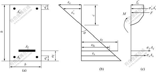
Fig.3 Strain and stress distributions in section: (a) Cross section; (b) Strain profile; (c) Stress profile
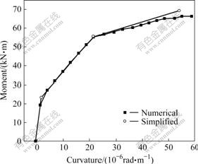
Fig.4 Comparison of moment―curvature relationships (Rsf=0.4, Rul=0.5, Rsf represents ratio of effective prestress in tendon to its ultimate strength, and Rul represents ratio of unbonded length of tendon to span of beam)
3.1 Deflection at concrete cracking
The mid-span deflection, Dc, at concrete cracking is given by:
 (6)
(6)
where Pc is the applied load at concrete cracking, EI1=Mc/(φc-φ0) is shown in Fig.1, and Mc=Pca is the moment of section at concrete cracking.
3.2 Deflection at tensile steel yielding
The mid-span deflection, Ds, at yielding of tensile steel is given by
 (7)
(7)
where Ps is the applied load at tensile steel yielding, EI2=(Ms-Mc)/(φs-φc) is illustrated in Fig.1, c1=Mca/Ms, and Ms is the moment at tensile steel yielding.
3.3 Ultimate deflection
The mid-span deflection, Du, at ultimate is given by:

 (8)
(8)
where Pu is the applied load at ultimate state, EI3=(Mu-Ms)/(φu-φs) is illustrated in Fig.1, s=Msa/Mu and Mu is the ultimate moment at concrete crushing or tendon rupture.
3.4 Verification of model
To assess the feasibility of the proposed model, more 18 beams tested by others were analyzed using the model in Ref.[14], the relative predicted ultimate loads and deflections are compared with test data in Fig.5 and Table 1. For those beams without tensile steel reinforcement, a point corresponding to a concrete compressive strain of 0.001 at the top of the surface of

Fig.5 Comparison of predicted and measured load-midspan deflection responses of three beams: (a) Beam No.PPR07UB2; (b) Beam No.PPR07PB2; (c) Beam No.PPR07FB2
the section, rather than the point at steel yielding, was determined on the moment―curvature and load―deflection curves. This is an appropriate way to deal with beams without tensile reinforcement in this case; both the moment―curvature and the load―deflection relationships after concrete cracking are essentially linear until the ultimate stage [13].
Good agreement between the predicted values and test data can be seen in Fig.5 for the overall load―deflection relationships for three beams tested by RIZKALLA [15], and also in Table 1 for the load and deflection at ultimate for all 24 beams, indicating that the proposed analytical model is valid.
4 Parametric study
A parametric study was conducted on beams with hybrid CFRP tendons and stainless steel reinforcements similar to the beams tested by RIZKALLA [15]. The beams were loaded in four-point bending as shown in Fig.1 and all had a rectangular section reinforced as indicated in Fig.3(a). The geometrical and mechanical characteristics of the beams are as follows.
Span, shear span and section of the beam:
l=3 300 mm, a=1 100 mm, b=160 mm, h=280 mm, as=32 mm,  = 20 mm, af=60 mm.
Table 1 Comparison of calculated and measured results

Tensile stainless steel:
As=157 mm2, σsy=669 MPa, Es1=177 GPa, Es2=266 MPa, esu = 0.403.
Compressive steel:
 =17.2 mm2, σsy = 600 MPa, Es1=200 GPa, Es2=0 MPa.
FRP tendons:
Af = 100.6 mm2, σfu = 2 95 GPa, Ef = 147 GPa.
Concrete in compression:
 = 45 MPa, e0 = 0.002, eu = 0.003 5
The ratio of effective prestress in the tendon to its material strength Rsf was taken as 0.5.
In the parametric study, the varied parameters consist of the unbonded length, ultimate compressive strain of concrete, effective prestress, amount of compressive reinforcement, and partial prestressing ratio(yPPR) defined as
 (9)
(9)
where Ap and fpu are the area and ultimate strength of the prestressed reinforcement, respectively, and As and fs are the area and the yield strength of the non-prestressed reinforcement, respectively. When a parameter was not selected as a variable, its value was taken as that given above.
The influences of various parameters on the behavior of beams with respect to load carrying capacity and ultimate deflection are indicated in Figs.6-10. In these figures, Uload refers to ultimate load-carrying capacity and Udef means ultimate mid-span deflection. The number after Uload or Udef refers to the value of Rsf, which is the ratio of effective prestress of an FRP tendon to its ultimate strength, and letter B or U after Uload or Udef indicates that the beam is fully bonded or fully unbonded, respectively.
4.1 Influence of unbonded length of tendon
The influence of unbonded length on the load-carrying capacity and ultimate deformation of the beam is shown in Fig.6. For the beam with Rsf=0.5, where the failure mode is concrete crushing regardless of the unbonded length, the load-carrying capacity of the beam decreases by 7% but the ultimate deflection increases by 7% as Rul increases from 0 to 1. For the beam with Rsf=0.65, where the failure mode changes from tendon rupture at Rul less than 0.75 to concrete crushing at Rul more than 0.75, the load-carrying capacity decreases by 4% and the ultimate deflection increases by 18%. It is also observed that the ultimate deflection of the beam with Rul more than 0.75 and failure mode of concrete crushing increases more slowly than that of the beam with Rul less than 0.75 and failure mode of FRP tendon rupture. As far as the beam with Rsf=0.8 is concerned, its failure mode is always tendon rupture,and its ultimate deflection increases by 38%, but its load-carrying capacity remains almost unchanged as Rul increases from 0 to 1.

Fig.6 Influence of unbonded length on load-carrying capacity and ultimate deformation of beam
Consequently, using the unbonded technique to increase the deformability of the beam is much more efficient for beams with a failure mode of tendon rupture. This is a result of the fact that the load-carrying capacity of a FRP-prestressed concrete beam is mostly dependent on the tendon stress at ultimate state, whereas the ultimate deflection is influenced mostly by the concrete compressive strain at the top surface of section in the same state. For the beam with a failure mode of FRP tendon rupture, with increasing unbonded length, the stress in FRP tendon will increase more slowly, which means that the beam will exhibit a larger deformation and a higher concrete compressive strain can be reached at the ultimate state. In this case, the increase of structural deformation is mostly resulted from the increase in concrete compressive strain at ultimate state, and since the FRP tendon will rupture anyway the increase of concrete compressive strain has only a slight effect on load-carrying capacity of the beam. For the beam with a failure mode of concrete crushing, increasing the unbonded length results in a decrease of the tendon stress at ultimate state, and a corresponding decreased load-carrying capacity and increased rotation. In this case, the ultimate strain of compressive concrete will remain constant, and the increase in structural deformation is due to an increase in rotation within unbonded length which has less effect than an increase in compressive strain of concrete.
4.2 Influence of ultimate compressive strain of concrete
Results relating to the influence of the ultimate compressive strain of concrete on a bonded beam and an unbonded beam are shown in Fig.7. It can be seen that

Fig.7 Influence of ultimate compressive strain of concrete on load carrying and ultimate deformation of beam
the ultimate deflection of both the bonded and unbonded beams are sensitive to concrete strain, and are almost directly proportional to the concrete ultimate strain, provided the failure mode is concrete crushing. Failure by concrete crushing occurs up to a strain of 0.004 1 for the bonded beam and 0.005 8 for the unbonded beam. The higher concrete compressive strain at transition from failure by concrete crushing to tendon rupture in the unbonded beam is due to the lower stress increase in the tendon at ultimate. However, the concrete strain has less effect on the load-carrying capacity.
When the ultimate strain of concrete is increased from 0.002 to 0.004, the ultimate deflection increases by about 100% for both fully bonded and fully unbonded beams, when the failure mode is concrete crushing, but the load-carrying capacity increases by only 20%. Ultimate deflection and load-carrying capacity for both bonded and unbonded beams are not affected by increasing the ultimate strain of the concrete when the failure mode is tendon rupture. Consequently, any measure taken to increase the ultimate strain of concrete will be effective only in beams with a failure mode caused by concrete crushing.
4.3 Influence of partial prestressing ratio (yPPR)
The influence of yPPR on the load-carrying capacity and ultimate deflection of bonded and unbonded beams is shown in Fig.8. yPPR was chosen to vary between 0.4 and 1.0 by changing the area of the tensile reinforcement (As). It can be seen that the load-carrying capacity decreases and ultimate deflection increases with the increase of yPPR. As yPPR increases from 0.4 to 1.0, the load-carrying capacity decreases and ultimate deflection increases by about 100%, and there is no significant difference in behavior between the fully bonded and the fully unbonded beams.
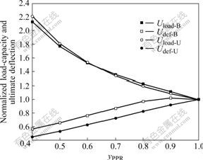
Fig.8 Influence of partial prestressing ratio on load carrying and ultimate deformation of beam
4.4 Influence of effective prestress
Fig.9 shows the influence of the effective prestress on the bonded and unbonded beams. It can be seen that the load-carrying capacity increases almost linearly with the effective prestress up to a certain level, after which it remains almost constant. The transition in behaviour is due to a change in the failure mode from concrete crushing to tendon rupture that occurs at Rsf=0.58 for the bonded beam and at Rsf=0.75 for the unbonded beam. On the other hand, ultimate deflection of the beam decreases with the increase of effective prestress regardless of the failure mode, but the decrease is more rapid for a failure mode by FRP tendon rupture. As Rsf increases from 0 to 0.6, the load-carrying capacity increases by 32% for the bonded beam and by 39% for the unbonded beam, while the corresponding ultimate deflection decreases by 33% for the bonded beam and 37% for the unbonded beam.

Fig.9 Influence of effective prestress on load carrying and ultimate deformation of beam
4.5 Influence of percentage of compressive steel
The influence of compressive reinforcement on the bonded and unbonded beams is shown in Fig.10. It can
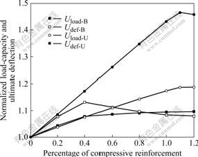
Fig.10 Influence of percentage of compressive reinforcement ( ) on load carrying and ultimate deformation of beam
be seen that the load-carrying capacity and ultimate deflection of the bonded beam increase with the increase of (percentage of compressive reinforcement) when is less than 0.4, for which the failure mode of the beam is concrete crushing. At >0.4 and failure mode is FRP rupture, the ultimate deflection decreases slightly and load-carrying capacity remains almost constant. For the unbonded beam, the ultimate deflection and load-carrying capacity increase almost linearly with up to 1.1 where the transition in failure mode from concrete crushing to tendon rupture occurs. The ultimate deflection is more sensitive to than to load-carrying capacity, in that ultimate deflection increases by 46.5% and load-carrying capacity by 18.8% as increases from 0 to 1.1. The higher value of compressive reinforcement percentage in transition state from failure of concrete crushing to failure of tendon rupture in the unbonded beam is due to the lower stress increase in the FRP tendon at ultimate, which is similar to the influence of ultimate compressive strain of concrete on the behavior of the beam.
5 Conclusions
(1) The influence of unbonded length of the tendon on the behaviour of a beam is dependent on the failure mode. Increasing unbonded length results in a decreased load-carrying capacity for a beam with failure mode by concrete crushing, but if has little effect on a beam whose the failure mode is tendon rupture. However, the deflection at ultimate increases with the increase of the unbonded length regardless of failure mode, but it is more pronounced when its failure occurs by tendon rupture.
(2) The ultimate deflection of both bonded and unbonded beams is sensitive to the ultimate compressive strain of the concrete, and is almost directly proportional to the concrete ultimate strain provided the failure mode is concrete crushing. However, concrete ultimate strain has less effect on the load-carrying capacity.
(3) The load-carrying capacity of a beam decreases while its ultimate deflection increases with increasing yPPR, and there is no significant difference in behavior between fully bonded and the fully unbonded beams.
(4) The load-carrying capacity and ultimate deflection for both bonded and unbonded beams increase with the increase of when the failure mode is by concrete crushing, while the load-carrying capacity remains almost constant and the ultimate deflection decreases slightly with the crease of when the failure mode is by FRP rupture. The ultimate deflection is more sensitive to than load-carrying capacity, especially for the unbonded beam with failure mode of concrete crushing.
References
[1] ERKI M A, RIZKALLA S H. FRP reinforcement for concrete structures [J]. Concrete International, 1993, 15(6): 48-53.
[2] American Concrete Institute. Presressing concrete with FRP tendons (ACI 440.4R-04) [S]. Michigan: Farmington Hill, 2004.
[3] SARAH L, ORTON A M, JAMES O, JIRSA P E, OGUZHAN B. Design considerations of carbon fiber anchors [J]. Journal of Composites for Construction, , 2008, 12(6): 608-616.
[4] HE Xue-jun, ZHOU Chao-yang, LI Yi-hui, XU Ling. Lagged strain of laminates in RC beams strengthened with fiber-reinforced polymer [J]. Journal of Central South University of Technology, 2007, 14(3): 431-435.
[5] MAADDAWY T, SOUDKI K. Strengthening of reinforced concrete slabs with mechanically-anchored unbonded FRP system [J]. Construction and Building Materials, 2008, 22(4): 444-445.
[6] YANG Jian, FANG Zhi. Behavior of prestressed ultra high performance concrete beams [J]. Key Engineering Materials, 2008, 400/402: 385-390.
[7] LEE J M, BURGOYNE C J. Analysis of concrete beams with partially bonded composite reinforcement [J]. Structure Journal, 2000, 97(2): 252-258.
[8] NAAMAN A E, TAN K H, JEONG S M, ALKHAIRI F M. Partially prestressed beams with carbon fiber composite strands: Preliminary tests evaluation [J]. ACI Special Publication, 1993, 138: 441-464.
[9] KATO T, HAYASHIDA N. Flexural characteristics of prestressed concrete beams with CFRP tendons [J]. ACI Special Publication, 1993, 138: 419-440.
[10] FANG Zhi, YANG Jian. Behaviors of concrete T-beams prestressed with CFRP tendons under cyclic loading [J]. Journal of China Railway Society, 2006, 28(1): 72-79. (in Chinese)
[11] CAMPBELL T I, RIZKALLA N S, TUNG D P. Pretension concrete beams with hybrid FRP/stainless steel reinforcement [C]// Proceedings CSCE Annual Conference. London: E & FN Spon, 2000: 419-426.
[12] FANG Z, CAMPBELL T I. Ductility of concrete beams prestressed with CFRP tendons [J]. Engineering Mechanics, 2005, 22(3): 190-197. (in Chinese)
[13] FANG Z, CAMPBELL T I. Prestressed concrete beams with hybrid FRP tendons and stainless steel reinforcements [C]// IABSE Symposium. Shanghai: China People’s Communication Publishing House, 2004: 703-709.
[14] NAKANO K, MASTUZAKI Y, FUKUYAMA H. Flexural performance of concrete beams reinforced with continuous fiber bars [J]. ACI Special Publication, 1993, 138: 743-766.
[15] RIZKALLA N S. Partial bonding and partial prestressing using stainless steel reinforcement for members pretressed with FRP [D]. Ontario: Queen’s University, 2000.
(Edited by CHEN Wei-ping)
Foundation item: Project (50478502) supported by the National Natural Science Foundation of China
Received date: 2008-09-15; Accepted date: 2008-11-15
Corresponding author: FANG Zhi, Professor; Tel: +86-731-8821432; E-mail: fangzhi@hnu.cn

