
Micro-analysis of explosive cladding interface of Nb/304L
WU Jin-ping(���ƽ), YANG Ying-li(��Ӣ��), ZHAO Heng-zhang(�Ժ���), YIN Jing-ou(���),
LIN Qiao(����), ZHAO Bin(�Ա�), GUO Di-zi(��ݶ��), SHU Hang-biao(�պ���)
Northwest Institute for Nonferrous Metal Research, Xi��an 710016, China
Received 15 July 2007; accepted 10 September 2007
Abstract: Nb/304L stainless steel composite plate was fabricated by explosive welding. Microstructure and content distribution along the interfaces of composite were studied by optical microscope (OM), scanning electron microscope (SEM) and energy spectrum (EDS). The results show that the waveform bonding can be obtained when proper dynamic parameters of explosive cladding are subjected. The interfaces undergo severe plastic deformation, which leads to the increase of hardness. There exist molten regions on both sides of wave peak and molten layers in bonding interfaces. And there is no obvious element diffusion on the both sides of bonding interface.
Key words: Nb/304L; explosive cladding; interface
1 Introduction
Nb and 304L stainless steel are important materials in the area of nuclear engineering. However, it is hard to combine them by general welding due to the difference in physical and chemical properties between them[1-2]. The welding between them can be resolved by explosive binding which has extensive applications in large plate welding[3-4]. Since Nb/304L composite is used in the corrosive environment, the quality of the welding interface will play an important role for application[5]. At the same time, feature and distribution of content in the melting layer between interfaces also have great effect on corrosion resistance for the composite.
It has been reported that metallurgy combination can be formed along the interface of Nb/304L explosive rods[6]. However, few have been reported on explosive welding on Nb/304L stainless steel plates. Explosion parameters have great effect on morphology of welding interfaces [7]. In this study, with proper parameters selected, Nb/304L stainless steel plate was successfully fabricated in laboratory by explosive binding technology. The feature of microstructure between the binding interfaces was studied. The results could be applied to the industry in future.
2 Experimental
The Nb plate (cladding plate) and the 304L stainless
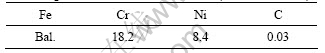
steel (base plate) subjected to annealing were used for explosive welding. The thicknesses of Nb and 304L plates are 1.5 mm and 10 mm, respectively. Ingredients of 304L are listed in Table 1.
Table 1 Ingredients of 304L stainless steel (mass fraction, %)
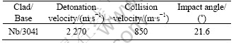
Low speed ammonium nitrate mixture dynamite was used in this study. Cladding plate was placed parallel to the base plate. Dynamic parameters were selected in the window of up limitation. Experimental dynamic parameters are listed in Table 2.
Table 2 Dynamic parameter for exploding processing
Parameters for explosive cladding are selected according to the following experiential formula[8]:
C=k (1)
(1)
S=0.2(��1+H) (2)
where C is unit area dynamite capacity; k is the coefficient related dynamite and cladding material; ��1 is thickness of cladding plate; ��1 is the density of cladding plate; S is the clearance between base and cladding plate; H is thickness of placing dynamite.
Specimens were cut from the center of the sheet in the plane parallel to the direction of jetting. After burnish and polish, specimens were eroded in corrosive ((V(HCl)?V(HNO3)=3?1). Microstructure and morphology along the interfaces were observed by optical microscopy (OM). Ingredients of interfaces was obtained by EDS based on JSM-5800 scanning electron microscopy (SEM). The microhardness around interfaces was measured by V-sclerometer.
3 Results and discussion
3.1 Nb/304L interface morphology
Morphologies of the Nb/304L interfaces are shown in Fig.1. The large wavy interface with molten region in swirl was observed. The periodical near-sine wave can be clearly found. The wavelength �� is 0.648 2 mm, and the amplitude A is 0.305 mm. ��/A is 0.471. Intermittent molten layers also occurred along the Nb/304L interface.
The waveform interface was formed just because of plasticity deformation of metal plate under the explosive impact wave. Molten region was formed at the wave peak because of thermal energy produced by high speed impact. Then the molten region at the wave peak was pressed for the later jet power. Finally, molten material fell down to the both sides of wave peak and formed the front and black molten region (Fig.1(b))[9].
On the other hand, large plasticity deformation occurred in base and clad plate after explosive cladding. From Fig.1(b), it can be found the stainless steel grains were elongated into streamline shape in 50-70 ��m far from bonding boundary.
The large wavelength, amplitude and the molten region on both sides of wave peak indicate that the collision velocity is very high during explosive cladding. Most materials in molten region located both sides of wave peak are jet material. All those material are harmful to the binding strength of cladding plate, which may cause failure during application later. Therefore, it��s necessary to adjust the process parameters for Nb/304l stainless steel explosive cladding.
3.2 Composition distribution on cladding interface
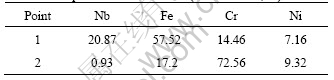
The feature of molten region in back swirl is shown in Fig.2. There exist particles distributing in back molten region. Compositions of back molten region (point 1) and particle (point 2) are listed in Table 3.
Molten region is comprised of Fe-Nb-Cr-Ni alloy formed from melting and solidifying of Nb and stainless steel. The particle (point 2) consists of Fe, Cr, Ni. During deformation by explosive welding, grains of the stainless steel will be subjected to high-speed severe plastic deformation, grains will be elongated and brushed off, therefore, the particle, which may be the fragment of stainless steel, is remained.
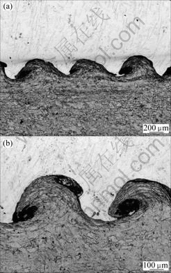
Fig.1 Nb/304L interface morphologies
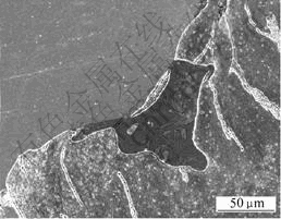
Fig.2 Molten region in back swirl and twins
On the side, twins are also found on the stainless steel far away from the bonding boundary. Twinning is the main type for plastic deformation under high strain speed. And it is one of the characters for high speed deformation[10-12]. It is indicated that the plastic deformation mechanism for the 304L base plate would be twinning.
Table 3 Compositions in back swirl (mass fraction, %)
The appearance of molten region in front swirl is shown in Fig.3. There also exist particles distributing in black molten region. Compositions of front molten region (point 1) and particle (point 2) are listed in Table 4. The particles contains Nb over 98% (mass fraction). The particles might be formed from the solidification of Nb liquids from the content and appearance of particles. Cladding and base plate would be melted at nearly the same time during cladding plate impacting the base plate in short time. During the following quick cooling, large Nb drops might have little time to diffuse with nearby stainless steel liquids, then the Nb particles would occur just like forming of Nb inclusion during casting Nb alloy.
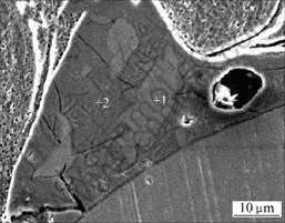
Fig.3 Molten region in front swirl
Table 4 Compositions in front swirl (mass fraction, %)
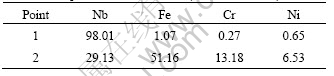
Similar with composition of the point 1 shown in Fig.2, the composition in point 2 shown in Fig.3 is also comprised of Fe, Nb, Cr, Ni formed from melting and solidification of Nb and stainless steel.
Besides the molten region on both side of wave peak, there exist some intermittent molten layers along the interface (Fig.4(a)). Element distribution lines from cladding plate to base plate (A��B��C) are shown in Fig.4(b). A, B and C are cladding layer, molten layer and base layer, respectively. The content of element Nb decreases slowly in molten layer, while contents of Fe, Cr, Ni increase slowly.
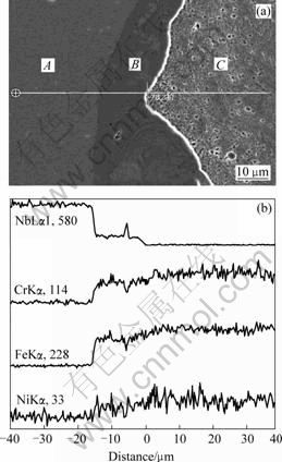
Fig.4 Elements distribution lines in molten layers: (a) Morphology; (b) Elements distribution lines of Nb, Cr, Fe and Ni
This suggests that the element in molten layer has very weak diffusion in cladding layer and base layer. The main component in intermittent molten layers is Fe-Nb-Cr-Ni alloy.
Just like the situation in base plate, there exists a large plastic deformation which contributes to the formation of a swirl region in cladding plate as shown in Fig.5(a). Elements distribution line from cladding plate to base plate (A��B��C) are shown in Fig.5(b). A, B and C are cladding layer, molten region and base layer respectively. The major component in molten region is also Fe-Nb-Cr-Ni alloy.
The element distribution in the Nb/304L stainless steel interface indicates that the main component in molten region and interface molten layer is Fe-Nb-Cr-Ni alloy formed from melting Nb and stainless steel. Furthermore, there also exist some Nb and stainless steel in molten region and molten layer. Diffusion is found on the both sides of molten layer. But the distance is very short because the explosive cladding process finishes in short time (about 10-5 s). There is little time for the diffusion of elements.
3.3 Distribution of microhardness in interface
With changing explosive cladding parameters, Nb/304L cladding plate was prepared. The interface waveform is shown in Fig.6(a). The size and quantity of molten region decrease. The distribution of microhardness beside the wave peak is shown in Fig.6(b). The microhardness has the trend as low��high��low from interface to stainless steel. On the cladding plate side, microhardness shows the feature as high��low from interface to Nb plate. These results of hardness are quite different from those of other reports in which the hardness at the bonding interface is the highest[13].
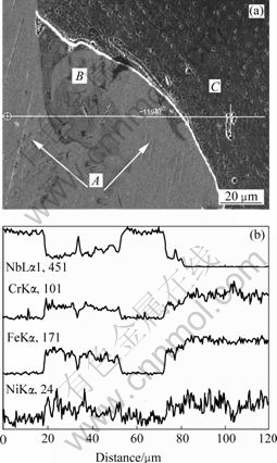
Fig.5 Elements distribution lines between interfaces: (a) Morphology; (b) Elements distribution lines of Nb, Cr, Fe and Ni
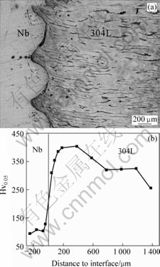
Fig.6 Interface of Nb/304L(a) and distribution of microhardness(b)
It has been reported that the change of microhardness is related to the thermal effect caused by explosion[14]. In this study, the working hardening and thermal effect are related with the change of microhardness beside interface. The microhardness has the trend as high��low from interface to Nb plate, which indicates that the influence of working hardening is larger than that of thermal softening. On the contrary, for stainless steel, recovery and recrystallization of grains near interface reduce the hardness caused by working hardening. Therefore, the microhardness of stainless steel reaches the maximum 200 ��m distance far from interface.
4 Conclusions
1) In the up limitation of explosive window��molten region is found on both sides of wave peaks along the interface of Nb/304L stainless steel composite, and intermittent melting layer is generated at the interface. Nb/304L explosion composite plate would be given a suitable interface with the wavy by adjusting the parameters of the explosion.
2) Nb and stainless steel with particle feature as well as Fe-Nb-Cr-Ni alloy solidified from Nb and stainless steel are found within the molten region and molten layer along the interface.
3) Very short-distant diffusion is found on both sides of the molten layer. Severely deformed belt with width in 50-70 ��m, featured in streamline shape, is found close to the side of 304L, while farther region deformed twins grains can be observed.
4) The maximum microhardness is observed close to interfaces of Nb layer, while the same phenomenon is found some distant from the interface in stainless steel.
References
[1] HE P, LIU D. Mechanism of forming interfacial intermetallic compounds at interface for solid state diffusion bonding of dissimilar materials[J]. Materials Science and Engineering A,2006, 437(2): 430-435.
[2] DURGUTLU A, G?LEN? B, FINDIK F. Examination of copper/stainless steel joints formed by explosive welding[J]. Materials & Design, 2005, 26(6): 497-507.
[3] KAHRAMAN N, G?LEN? B, FINDIK F. Joining of titanium/stainless steel by explosive welding and effect on interface[J]. Journal of Materials Processing Technology,2005, 169(2): 127-133.
[4] MAMALIS A G, VAXEVANIDIS N M, SZALAY A. Fabrication of trimetallic strips by explosive cladding and rolling[J]. Journal of Materials Processing Technology,1994, 45(1/4): 407-414.
[5] KAHRAMAN N, GULENC B, FINDIK F. Corrosion and mechanical-microstructural aspects of dissimilar joints of Ti�C6Al�C4V and Al plates[J]. International Journal of Impact Engineering, 2007, 34(8):1423-1432.
[6] JIAO Yong-gang, MA Dong-kang, GUO Yue-xia, PEI Da-rong. Producing Nb-stainless steel clad rods by outer-clad explosive welding method[J]. Explosion and Whock Waves, 2004, 24(2): 189-192. (in Chinese)
[7] VAIDYANATHAN P V, RAMANATHAN A R. Design for quality explosive welding[J]. Journal of Materials Processing Technology, 1992, 32(1/2): 439-448.
[8] ZHENG Zhe-min, YANG Zhen-sheng. Explosive machining[M]. Beijing: National Dependence Industry Press, 1981. (in Chinese)
[9] SHAO Bing-huang, ZHANG Kai. Explosive welding principal and it��s application[M]. Dalian: Dalian University of Science and Technology Press, 1987. (in Chinese)
[10] CHRISTIAN J W, MAHAJAN S. Deformation twinning[J]. Progress in Material Science, 1995, 39(1/2): 1-157.
[11] MEYERSA M A, XUB Y B, XUEA Q, P?REZ-PRADOA M T, MCNELLEY T R. Microstructural evolution in adiabatic shear iocalization in stainless steel[J]. Acta Materialia, 2003, 51(5): 1307-1325.
[12] CHEN G L, ZHANG L C. Deformation mechanism at large strains in a high-Nb-containing TiAl at room temperature[J]. Materials Science and Engineering A, 2002, A329/331: 163-170.
[13] ZHENG Yuan-mou, HUANG Rong-guang, CHEN Shi-hong. Hardening of metal in explosive welding composite material[J]. Mining & Metallurgy, 1999, 8(3): 60-64. (in Chinese)
[14] YANG Yang, LI Zheng-hua, CHENG Xin-lin, ZHU Xiao-bei, PEI Da-rong, GAO Wen-zhu. Microstructure of Cu/Mo/Cu explosive clad interface[J]. Rare Metal Materials and Engineering, 2001, 30(5): 339-341. (in Chinese)
Foundation item: Project (2007CB613807) supported by the National Basic Research Program of China
Corresponding author: WU Jin-ping; Tel: +86-29-86231078-807; E-mail: jinpingwu7@126.com
(Edited by YANG You-ping)

