Trans. Nonferrous Met. Soc. China 23(2013) 1367-1374
Electrochemical discharging performance of 3D porous magnesium electrode in organic electrolyte
Gang CHENG1, Qiang XU1, Xi ZHAO1, Fei DING2, Jing ZHANG2, Xing-jiang LIU1,2, Dian-xue CAO3
1. School of Chemical Engineering and Technology, Tianjin University, Tianjin 300072, China;
2. National Key Laboratory of Science and Technology on Power Sources Laboratory, Tianjin Institute of Power Sources, Tianjin 300384, China;
3. Key Laboratory of Superlight Materials and Surface Technology of Ministry of Education, Harbin Engineering University, Harbin 150001, China
Received 25 October 2011; accepted 5 January 2012
Abstract: A novel type of porous magnesium electrode with a stable 3D copper foam as current collectors for the organic magnesium-air battery was prepared by both amperostatic and pulsed electrodeposition of magnesium on copper foam substrates in an electrolyte of 1 mol/L EtMgBr/THF solution, respectively. Optimal parameters of the pulsed electrodeposition were obtained using a bending cathode at the right angle. The surface morphology of the porous electrode was investigated by SEM, and the discharging performance of the porous magnesium electrode was detected by the chronoamperometric measurement. The electrochemical stability of 3D copper foam current collectors was examined by cyclic voltammetry, SEM and ICP-OES analyses. The results show that the rate capability of the porous magnesium electrode with a stable 3D copper foam as a current collector is better than that of the planar magnesium electrode, and the rate capability of the porous magnesium electrode prepared by the pulsed electrodeposition is superior to that of the porous magnesium electrode prepared by the amperostatic electrodeposition. The 3D structure of copper foam current collectors of the porous magnesium electrode could keep stable during the discharging process.
Key words: metal semi-fuel cell; porous magnesium electrode; copper foam; electrodeposition; discharge behavior
1 Introduction
Magnesium semi-fuel cells have been studied as the undersea power sources due to their high energy density, stable discharging ability, short mechanical recharging time, long dry storage life, excellent ability to work at high pressure, environmental acceptability, good reliability, high safety, and low cost [1-8]. For example, the energy density of the magnesium-air battery system can be up to 3910 W・h/kg [9]. Magnesium as anode has the advantages of high Faradic capacity, high specific energy, more negative standard electro-reduction potentials, and good discharging performance in the aqueous electrolyte [10,11]. Therefore, thermody- namical magnesium anodes should exhibit very negative potentials. However, in fact, magnesium anodes operate at significantly less negative potentials in most of aqueous electrolyte due to the following two reasons: 1) Magnesium is normally covered by the passive oxide film which causes a delay in reaching a steady state and reduces the discharging rate; 2) Magnesium undergoes a parasitic corrosion reaction or self discharging, resulting in the reduction of Columbic efficiency (less than 100% utilization of the metal) and the evolution of hydrogen [12,13]. These two drawbacks have restrained applications of traditional magnesium-air batteries.
With the development of the lithium-air battery, the organic metal semi-fuel cell which used organic solutions as the electrolyte has received great attention [14-16]. It has been known that magnesium anodes are not passivated in ethereal solutions of Grignard reagents (RMgX, where R=alkyl, aryl groups; X=halide: Cl, Br) and complexes of the Mg(AX4-nRn′R′n′′)2 type (A=Al, B; X=Cl, Br; R, R′=alkyl or aryl groups; n′+n′′=n) [17-19]. If using ethereal solutions of Grignard reagents as the electrolyte of the magnesium-air battery instead of the aqueous electrolyte, the above two drawbacks of magnesium anodes in the aqueous electrolyte could be solved. However, the conductivity of ethereal solutions of Grignard reagents is much lower than that of the aqueous electrolyte. Therefore, there are great scientific and technological values to improve the properties of magnesium anodes in the organic electrolyte so as to enhance electrochemical performances of the organic magnesium-air battery.
Recently, a kind of three-dimensional (3D) porous metal anode of lithium-ion batteries has been prepared by electrodeposition on copper foam current collectors [20-22]. These 3D porous metal anodes of lithium-ion batteries have an excellent rate capability attributed to the unique porous structure and the large surface area for the fast mass transport and rapid surface reactions [23].
In this work, a novel type of 3D porous magnesium electrodes as anodes for the organic magnesium-air battery were prepared by two electrodeposition methods on copper foam substrates which were used as the current collectors. The surface morphologies of these porous magnesium electrodes were characterized by field emission scanning electron microscopy (SEM), and the discharging performance of the porous magnesium electrode in an electrolyte of 1 mol/L EtMgBr/THF solution was tested by chronoamperometric measurements. The electrochemical stability of 3D copper foam current collectors was examined by cyclic voltammetry, SEM and ICP analyses.
2 Experimental
All preparations and electrochemical measurements of three kinds of magnesium electrodes (planar and porous) were carried out in an argon atmosphere glove box (MIKROUNA Advanced 2440/75), where concentrations of water and oxygen were kept below 1×10⁻⁶ at room temperature.
2.1 Preparation of planar magnesium electrode
The planar magnesium electrode was prepared by amperostatic electrodeposition of magnesium on a planar copper foil (the area of copper foil was 0.25 cm2) on a PARSTAT 2273 electrochemical workstation in 1 mol/L EtMgBr/THF solution. The anode of amperostatic electrodeposition was a pure magnesium foil. The current density was 2 mA/cm2 and the electrodeposition time was 7200 s.
Both Grignard reagents (EtMgBr) with concentration of 1 mol/L in tetrahydrofuran (THF) solution and the pure tetrahydrofuran (THF, 99.9%) were obtained from ACROS Organics company. Pure magnesium foils were prepared by machining a 99.99% pure magnesium ingot (Jiuli Mg Co. Ltd.). Copper foils (Bonstan metallic Co. Ltd) were battery grade pure. Both copper and magnesium foils were polished with a corundum suspension, and rinsed ultrasonically in a pure acetone solution and pure tetrahydrofuran solutions before using, respectively.
2.2 Optimization of pulsed electrodeposition parameters
In addition to the average current density and the electrodeposition time, the other parameters of the pulsed electrodeposition were obtained by electrodeposition measurements on the bending cathode at a right angle. Figure 1 shows the schematic diagram of the bending cathode at a right angle in an electrolytic cell. The surface areas of both sides of the crease are equivalent, which are 0.25 cm2. The whole surface area of the flattened bending cathode is 2 cm×0.25 cm. Electrodeposition measurements were conducted on the bending cathode at a right angle in 1 mol/L EtMgBr/THF solution and the time of electrodeposition measurements was 3600 s. After electrodeposition measurements, the bending cathode at a right angle was flattened to a plate. The optimal pulsed electrodeposition parameters were obtained by measuring the amount of magnesium electrodeposit with different pulsed parameters on the central region of the flattened bending cathode (2 cm×0.125 cm) by energy dispersive spectrometry (EDS) analyses. The more the magnesium was electrodeposited near the crease, the better the pulsed parameters were selected. In the process of electrodeposition measurements, three kinds of pulsed electrodeposition parameters (the average current density, the pulsed frequency and the duty cycle) were used as the independent variable, respectively.

Fig. 1 Schematic diagram of bending cathode at right angle in electrolytic cell
2.3 Preparation of porous magnesium electrode
The porous magnesium electrodes were prepared by both the amperostatic electrodeposition and the pulsed electrodeposition on 3D copper foam current collectors (the apparent surface area of each porous magnesium electrode was the same as 0.25 cm2) with the PARSTAT 2273 electrochemical workstation in 1 mol/L EtMgBr/ THF solution, respectively. The average pulsed current density of the pulsed electrodeposition was 2 mA/cm2, which was the same as that of the amperostatic electrodeposition. The electrodeposition time of two electrodeposition methods was equivalent, which was 7200 s. The anode in the electrolytic cell was pure magnesium foil.
The 3D copper foam current collectors were rinsed ultrasonically in a dry acetone solution prior to electrodeposition. The treatment of pure magnesium foils was similar to the preparation process of the planar magnesium electrode. The 3D copper foams (Zhongwei Materials Co. Ltd.) were battery grade pure, and the number of pores per linear inch (PPI) was 110.
2.4 Measurements of three kinds of magnesium electrodes
The surface morphologies of three kinds of magnesium electrodes (planar and porous) were observed with a field emission scanning electron microscope (SEM, Hitachi S-4800). The surface components of three kinds of magnesium electrodes were analyzed with a energy dispersive spectrometer (EDS, HORIBA Emax-350).
The chronoamperometric tests of three kinds of magnesium electrodes (planar and porous) were carried out using a PARSTAT 2273 electrochemical workstation in a homemade three-electrode electrolytic cell inside the glove box at room temperature. The working electrode was the planar or the porous magnesium electrode, while pure magnesium foils were served as both counter and reference electrodes. The electrolyte was 1 mol/L EtMgBr/THF solution.
2.5 Measurement of stability for copper foam current collectors
The cyclic voltammetry measurement was conducted in the homemade three-electrode electrolytic cell inside the glove box at room temperature using a PARSTAT 2273 electrochemical workstation. The working electrode was the copper foam current collector, while pure magnesium foils were used as both counter and reference electrodes. The cyclic voltammetry scanning rate was 10 mV/s and the electrolyte was 1 mol/L EtMgBr/THF solution. The chronoamperometric measurement was operated at a potential of 0.7 V (vs Mg) and the discharging time was 7200 s.
The surface morphologies of copper foam current collectors before and after the chronoamperometric tests were also investigated by SEM. Elemental compositions of the electrolyte were analyzed by an iCAP6300 inductively coupled plasma optical emission spectrometer(ICP-OES)after the chronoamperometric test.
2.6 Measurement of self-discharge for porous magnesium electrode
Two identical porous magnesium electrodes were prepared by the amperostatic electrodeposition. The electrodeposition time was equal, which was 14400 s. The electrodeposition conditions were the same as that of the above-mentioned porous magnesium electrodes. The self-discharge tests of the above two identical porous magnesium electrodes were carried out by the chronoamperometric test at an anodic potential of 0.5 V (vs Mg) before and after storage for 7 d, respectively.
3 Results and discussion
3.1 Surface morphologies of planar magnesium electrode
Figure 2 shows the SEM image of the planar magnesium electrode. It can be seen that the magnesium deposits on the planar copper foil are compact and smooth. The average content of magnesium deposits on a planar copper foil is around 85.6%, which was detected by EDS.

Fig. 2 SEM image of magnesium deposited on planar copper foil
3.2 Optimization of pulsed electrodeposition parameters
The results of EDS analyses for the pulsed electrodeposition on the bending cathode at a right angle are summarized in Table 1. As shown in Table 1, the amount of magnesium electrodeposit on the bending cathode at a right angle increases with the increase of the average current density of the pulsed electrodeposition for all samples. However, magnesium dendrites would be generated on the surface of the bending cathode at a right angle when the average current density of the pulsed electrodepositions was above 2.0 mA/cm2, thus, the optimal average pulsed current density was determined as 2.0 mA/cm2. Both the optimal frequency (1 Hz) and the optimal duty cycle (20%) of the pulsed electrodeposition were obtained by altering the corresponding independent variable while fixing the other electrical parameters of the pulsed electro- deposition, respectively.
Table 1 Optimization results of pulsed electrodeposition parameters

Figure 3 shows the SEM images of the bending cathodes after flatting, which were electrodeposited with different pulsed parameters at a right angle. It can be found that the amount of magnesium deposits obtained by the optimal pulsed parameter, as shown in Fig. 3(d), is the maximum among these samples.
3.3 Surface morphologies of porous magnesium electrode
Figure 4 shows the SEM images of the porous magnesium electrodes prepared by the amperostatic and pulsed electrodeposition. The surface morphologies of these porous magnesium electrodes are irregular and coarse, and there are some nodules and particles dispersing unevenly on the surface of the copper foam. Most of magnesium deposits prepared by the amperostatic electrodeposition are found on the surface outside the holes of the copper foam (Fig. 4(a)), and few magnesium deposits are deposited inside the holes of the copper foam (insert of Fig. 4(a)). Unlike the amperostatic electrodeposition, the magnesium deposits prepared by the pulsed electrodeposition are found in both outside and inside the holes of the copper foam (Fig. 4(b)). These results indicate that the surface area of the porous magnesium electrode is larger than that of the planar magnesium electrode and the surface area of the porous magnesium electrode prepared by the pulsed electrodeposition is larger than that of the porous magnesium electrode prepared by the amperostatic electrodeposition.

Fig. 3 SEM images of flatting bending cathodes at right angle electrodeposited with different pulsed parameters

Fig. 4 SEM images of porous magnesium electrodes prepared by amperostatic electrodeposition and pulsed electrodeposition (Insert shows its enlarged morphology)
3.4 Measurements of chronoamperometry
Chronoamperometric measurements at various anodic potentials in 1 mol/L EtMgBr/THF solution were carried out to evaluate the discharging performance of three kinds of magnesium electrodes (planar and porous). Figure 5 shows the current―time curves of three kinds of magnesium electrodes at various anodic potentials. It can be seen that all the anodic currents of these three kinds of magnesium electrodes increase with the growth of anodic potentials. For both porous magnesium electrodes, the anodic currents decrease relatively fast than that of the planar magnesium electrode at higher anodic potentials (larger discharge currents), which is attributed to the fast dissolution rate of magnesium deposits at high discharge currents.
Figure 6 shows the current―time curves of three kinds of magnesium electrodes discharged at the same anodic potential (0.7 V vs Mg). The maximum anodic current of the porous magnesium electrode prepared by the pulsed electrodeposition is close to 11 mA/cm2, and the maximum anodic current of the porous magnesium electrode prepared by the amperostatic electrodeposition is around 8.1 mA/cm2. However, the maximum anodic current of the planar magnesium electrode is near 6.2 mA/cm2. These results demonstrate that the rate capability of the porous magnesium electrode is superior to that of the planar magnesium electrode, and the rate capability of the porous magnesium electrode prepared by the pulsed electrodeposition is better than that of the porous magnesium electrode prepared by the amperostatic electrodeposition. The results are in good consistent with above analytical results of surface morphologies.
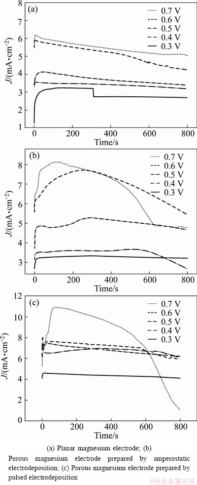
Fig. 5 Current―time curves for three magnesium electrodes at various anodic potentials
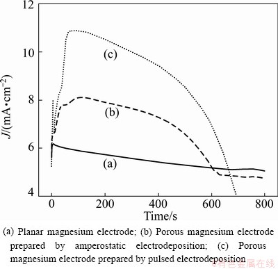
Fig. 6 Current―time curves for three kinds of magnesium electrodes discharged at anodic potential of 0.7 V (vs Mg)

Fig. 7 Cyclic voltammogram for magnesium electrodeposition and dissolution on copper foam current collector (Scan rate: 10 mV/s)
3.5 Stability of copper foam current collectors
Figure 7 shows the cyclic voltammogram obtained through the process of magnesium electrodeposition and dissolution on copper foam current collectors in 1 mol/L EtMgBr/THF solution. It can be seen that there is a constant current level range between -0.2 V and 1.6 V (vs Mg) in this cyclic voltammogram and the current density within this level range is proximately equal to zero. There is only one anodic peak in the anodic polarization curve, which suggests the dissolution of magnesium [17]. These results represent that the copper foam current collectors did not dissolve within the range of magnesium redox potentials in 1 mol/L EtMgBr/THF solution.
Figure 8 shows the SEM images of the copper foam current collector before and after the chronoamperometric test at a potential of 0.7 V (vs Mg). The surface morphologies of copper foam current collectors have almost no significant difference before and after the chronoamperometric test. The results further indicate that the copper foam current collectors did not dissolve during discharging in 1 mol/L EtMgBr/THF solution.

Fig. 8 SEM images of copper foam collector before (a) and after (b) chronoamperometric measurement at anodic potential of 0.7 V (vs Mg)
The analytical results of ICP-OES for the electrolyte after discharging are given in Table 2. The electrolyte after discharging contains only a small amount of metallic elements except for the magnesium. Since the copper content of the electrolyte (0.0755×10⁻⁶) is lower than its limiting detection concentration (0.1×10⁻⁶), it can be identified that the copper foam current collector did not dissolve during discharging in 1 mol/L EtMgBr/THF solution.
Table 2 ICP-OES analysis results of electrolyte after discharge

All above analytical results show that the 3D structure of copper foam current collectors of the porous magnesium electrode can keep high electrochemical stability during the discharging process.
3.6 Self-discharge characteristics of porous electrode
Figure 9 represents the results of chrono- amperometric measurements for two identical porous magnesium electrodes prepared by the amperostatic electrodeposition after different storage time. The measurement results demonstrate that the discharging capacity of the porous magnesium electrode is a function of the storage time.
The self-discharge rate (C) of the porous magnesium electrode is 3.37% per day, which is calculated by Eq. (1) [24]:
 (1)
(1)
where Cini is the initial discharging capacity and Cret is the retention capacity.

Fig. 9 Current―time curves for two identical porous magnesium electrodes at anodic potential of 0.5 V (vs Mg) after different storage time
4 Conclusions
1) A novel type of porous magnesium electrodes with a stable 3D copper foam current collectors were successfully fabricated by the amperostatic and the pulsed electrodeposition, respectively.
2) The results of chronoamperometric measure- ments at various anodic potentials in 1 mol/L EtMgBr/ THF solution demonstrate that the rate capacity of the porous magnesium electrode is obviously superior to that of the planar magnesium electrode. Furthermore, the rate capability of the porous magnesium electrode prepared by the pulsed electrodeposition is much better than that of the porous magnesium electrode prepared by the amperostatic electrodeposition.
3) During the discharging process, the 3D structure of copper foam current collectors of the porous magnesium electrode can keep a high electrochemical stability. The self-discharge rate of the porous magnesium electrode is approximately 3.37% per day.
References
[1] MA Y B, LI N, LI D Y, ZHANG M L, HUANG X M. Performance of Mg-14Li-1Al-0.1Ce as anode for Mg-air battery [J]. Journal of Power Sources, 2011, 196: 2346-2350.
[2] YANG W Q, YANG S H, SUN W, SUN G Q, XIN Q. Nanostructured palladium-silver coated nickel foam cathode for magnesium-hydrogen peroxide fuel cells [J]. Electrochim Acta, 2006, 52: 9-14.
[3] HASVOLD  , STRKERSEN N J, FORSETH S, LIAN T. Power sources for autonomous underwater vehicles [J]. Journal of Power Sources, 2006, 162: 935-942.
[4] MEDEIROS M G, BESSETTE R R, DESCHENES C M, PATRISSI C J, CARREIRO L G, TUCKER S P, ATWATER D W. Magnesium-solution phase catholyte semi-fuel cell for undersea vehicles [J]. Journal of Power Sources, 2004, 136: 226-231.
[5] HASVOLD , LIAN T, HAAKAAS E, STRKERSEN N, PERELMAN O, CORDIER S. CLIPPER: A long-range, autonomous underwater vehicle using magnesium fuel and oxygen from the sea [J]. Journal of Power Sources, 2004, 136: 232-239.
[6] HASVOLD , STRKERSEN N. Electrochemical power sources for unmanned underwater vehicles used in deep sea survey operations [J]. Journal of Power Sources, 2001, 96: 252-258.
[7] MEDEIROS M G, DOW E G. Magnesium-solution phase catholyte seawater electrochemical system [J]. Journal of Power Sources, 1999, 80: 78-82.
[8] WILCOCK W S D, KAUFFMAN P C. Development of a seawater battery for deep-water applications [J]. Journal of Power Sources, 1997, 66: 71-75.
[9] LI W Y, LI C S, ZHOU C Y, MA H, CHEN J. Metallic magnesium nano/mesoscale structures: Their shape-controlled preparation and Mg/Air battery applications [J]. Angew Chem Int Ed, 2006, 45: 6009-6012.
[10] CAO D X, CAO X, WANG G L, WU L, LI Z S. Electrochemical discharge performance of Mg-Li based alloys in NaCl solution [J]. Journal of Solid-state Electrochemistry, 2010, 14: 851-855.
[11] FENG Y, WANG R C, YU K, PENG C Q, ZHANG J P, ZHANG Z. Activation of Mg-Hg anodes by Ga in Nacl solution [J]. Journal of Alloys and Compounds, 2009, 473: 215-219.
[12] CAO D X, WU L, SUN Y, WANG G L, LV Y Z. Electrochemical behavior of Mg-Li, Mg-Li-Al and Mg-Li-Al-Ce in sodium chloride solution [J]. Journal of Power Sources, 2008, 177: 624-630.
[13] SIVASHANMUGAM A, KUMAR T P, RENGANATHAN N G, GOPUKUMAR S. Performance of a magnesium-lithium alloy as an anode for magnesium batteries [J]. Journal of Applied Electrochemistry, 2004, 34: 1135-1139.
[14] PADBURY R, ZHANG X W. Lithium-oxygen batteries-limiting factors that affect performance [J]. Journal of Power Sources, 2011, 196: 4436-4444.
[15] WANG D Y, XIAO J, XU W, ZHANG J G. High capacity pouch-type Li-air batteries [J]. Journal of the Electrochemical Society, 2010, 157(7): A760-A764.
[16] XU W, XIAO J, ZHANG J, WANG D Y, , ZHANG J G. Optimization of nonaqueous electrolytes for primary lithium/air batteries operated in ambient environment [J]. Journal of the Electrochemical Society, 2009, 156(10): A773-A779.
[17] AURBACH D, LU Z, SCHECHTER A, GOFER Y, GIZBAR H, TURGEMAN R, COHEN Y, MOSHKOVLCH M, LEVI E. Prototype systems for rechargeable magnesium batteries [J]. Nature, 2000, 407: 724-727.
[18] AMIR N, VESTFRID Y, CHUSID O, GOFER Y, AURBACH D. Progress in nonaqueous magnesium electrochemistry [J]. Journal of Power Sources, 2007, 174: 1234-1240.
[19] GOFER Y, CHUSID O, GIZBAR H, VIESTFRID Y, GOTTLIEB H E, MARKS V, AURBACH D. Improved electrolyte solutions for rechargeable magnesium batteries [J]. Electrochemical and Solid-State Letters, 2006, 9(5): A257-A260.
[20] KE F S, HUANG L, CAI J S, SUN S G. Electroplating synthesis and electrochemical properties of macroporous Sn-Cu alloy electrode for lithium-ion batteries [J]. Electrochim Acta, 2007, 52: 6741-6747.
[21] NISHIKAWA K, DOKKO K, KINOSHITA K, WOO S W, KANAMURA K. Three-dimensionally ordered macroporous Ni-Sn anode for lithium batteries [J]. Journal of Power Sources, 2009, 189: 726-729.
[22] HUANG L, YANG Y, XUE L J, WEI H B, KE F S, LI J T, SUN S G. Electrodeposition and electrochemical properties of novel ternary tin-cobalt-phosphorus alloy electrodes for lithium-ion batteries [J]. Electrochimistry Communications, 2009, 11: 6-9.
[23] SHIN H C, LIU M. Three-dimensional porous copper-tin alloy electrodes for rechargeable lithium batteries [J]. Advanced Functional Materials, 2005, 15: 582-586.
[24] RYU H S, AHN H J, KIM K W, AHN J H, CHO K K, NAM T H. Self-discharge characteristics of lithium/sulfur batteries using TEGDME liquid electrolyte [J]. Electrochim Acta, 2006, 52: 1563-1566.
三维结构多孔镁电极在有机电解液中的放电性能
程 刚1,徐 强1,赵 夕1,丁 飞2,张 晶2,刘兴江1,2,曹殿学3
1. 天津大学 化工学院,天津 300072;
2. 天津电源技术研究所 化学与物理电源重点实验室,天津 300384;
3. 哈尔滨工程大学 超轻材料与表面技术教育部重点实验室,哈尔滨 150001
摘 要:为了提高有机镁-空气电池的放电性能,将1 mol/L EtMgBr/THF溶液作为电解液,分别采用恒电流沉积和脉冲沉积的方法在泡沫铜基体上电沉积镁制备一种具有三维结构的多孔镁电极。利用直角弯曲阴极法优化脉冲电沉积的参数。通过扫描电子显微镜观察多孔镁电极的表面形貌,采用计时电流法考察多孔镁电极的放电性能。此外,还通过循环伏安、扫描电子显微镜和电感耦合等离子体发射光谱仪等方法考察泡沫铜集流体的三维结构稳定性。结果表明,多孔镁电极的倍率放电性能明显优于平板镁电极的;采用脉冲电沉积方法制备的多孔镁电极的倍率放电性能优于采用直流电沉积方法制备的多孔镁电极。在放电过程中,泡沫铜集流体的三维结构稳定性保持良好。
关键词:金属-半燃料电池;多孔镁电极;泡沫铜;电沉积;放电行为
(Edited by Xiang-qun LI)
Foundation item: Project (20973124) supported by the National Natural Science Foundation of China; Project supported by Key Laboratory of Superlight Materials and Surface Technology, Ministry of Education (Harbin Engineering University), China
Corresponding author: Qiang XU; Tel: +86-13702108410; E-mail: xuqiang_tj@163.com; Xing-jiang LIU; E-mail: xjliu@nklps.org
DOI: 10.1016/S1003-6326(13)62605-9

