Primary and recency effects based on loading path in classical plasticity
��Դ�ڿ������ϴ�ѧѧ��(Ӣ�İ�)2020���9��
�������ߣ��۷� ������ ���� ��ٻ �˾� ������
����ҳ�룺2592 - 2605
Key words��isotropic linear hardening; stress path; strain path; primary effect; recency effect
Abstract: We have established an elastoplastic analysis model to explore the effect of loading path in an incompressible thin-walled tube under the combined action of axial force and torque based on Mises yield condition and isotropic linear hardening assumption. Further, four stress areas (��x, ��x) are divided according to the characteristics of the final stress, and the plastic stress-strain relationship of twelve stress paths in different stress areas is derived. The ��primary effect�� of the stress path on plastic strain is demonstrated, namely, the plastic strain caused by the pre-loaded stress in path A (tensile stress is initially applied, followed by shear stress) is always greater than that caused by the post-loaded stress in path C (shear stress is initially applied, followed by tensile stress) irrespective of the value of final stress. The ��recency effect�� of the strain path on the stress is also established, which indicates that the stress caused by the post-loaded strain in path A is always greater than that caused by the pre-loaded strain in path C irrespective of the value of final strain. From the perspective of deformation, the ��primary effect�� of the stress path on the plastic strain and the ��recency effect�� of the strain path on the stress are unified. These effects are succinct and universal, and they provide useful insights on the plastic stress-strain relationship under different loading paths. Furthermore, they can serve as a useful reference for optimizing the processing technologies and construction procedures.
Cite this article as: GAO Yue, SHAO Fei, FAN Peng-xian, XU Qian, GU Juan, WANG Shang-long. Primary and recency effects based on loading path in classical plasticity [J]. Journal of Central South University, 2020, 27(9): 2592-2605. DOI: https://doi.org/10.1007/s11771-020-4484-x.

J. Cent. South Univ. (2020) 27: 2592-2605
DOI: https://doi.org/10.1007/s11771-020-4484-x

GAO Yue(����)1, SHAO Fei(�۷�)1, FAN Peng-xian(������)2,XU Qian(��ٻ)1, GU Juan(�˾�)2, WANG Shang-long(������)3
1. Field Engineering College, Army Engineering University of PLA, Nanjing 210007, China;
2. Defense Engineering College, Army Engineering University of PLA, Nanjing 210007, China;
3. Engineering Design Institute of the Army Research Institute, Nanjing 210018, China
 Central South University Press and Springer-Verlag GmbH Germany, part of Springer Nature 2020
Abstract: We have established an elastoplastic analysis model to explore the effect of loading path in an incompressible thin-walled tube under the combined action of axial force and torque based on Mises yield condition and isotropic linear hardening assumption. Further, four stress areas (��x, ��x) are divided according to the characteristics of the final stress, and the plastic stress-strain relationship of twelve stress paths in different stress areas is derived. The ��primary effect�� of the stress path on plastic strain is demonstrated, namely, the plastic strain caused by the pre-loaded stress in path A (tensile stress is initially applied, followed by shear stress) is always greater than that caused by the post-loaded stress in path C (shear stress is initially applied, followed by tensile stress) irrespective of the value of final stress. The ��recency effect�� of the strain path on the stress is also established, which indicates that the stress caused by the post-loaded strain in path A is always greater than that caused by the pre-loaded strain in path C irrespective of the value of final strain. From the perspective of deformation, the ��primary effect�� of the stress path on the plastic strain and the ��recency effect�� of the strain path on the stress are unified. These effects are succinct and universal, and they provide useful insights on the plastic stress-strain relationship under different loading paths. Furthermore, they can serve as a useful reference for optimizing the processing technologies and construction procedures.
Key words: isotropic linear hardening; stress path; strain path; primary effect; recency effect
Cite this article as: GAO Yue, SHAO Fei, FAN Peng-xian, XU Qian, GU Juan, WANG Shang-long. Primary and recency effects based on loading path in classical plasticity [J]. Journal of Central South University, 2020, 27(9): 2592-2605. DOI: https://doi.org/10.1007/s11771-020-4484-x.
1 Introduction
The primary and recency effects are crucial theories in psychology and pedagogy. The primary effect implies that in social cognition, the first information or stimulus provided to an individual leaves him/her with the most striking impression, which is also called the first impression effect. In contrast, the recency effect refers to the psychological effect of recent stimuli that promotes the formation of impressions, namely, the newly obtained information has a greater impact on individuals than the previously obtained information. Presently, investigations on primary and recency effects are limited to social sciences [1-3], and relevant studies in the fields of mechanical engineering and material engineering are lacking in the exiting literature.
According to classical mechanics and practical experience, when a material is loaded into the plastic deformation stage, the stress or strain path has a significant impact on the final plastic strain or stress state. Existing studies mainly focused on the effect of loading path in engineering materials through laboratory experiments [4-9] and numerical methods [10, 11] to establish a quantitative relationship between the plasticity behavior and loading history, thus improving the plastic constitutive model of materials [12]. Most of these studies concentrated on specific materials, especially geotechnical materials. The unloading effect [13], microstructural study [14-16], fatigue prediction [17-19], and principal stress rotation effect [20] are closely related with the loading path, which plays an important role in exploring the influence of loading history on the mechanical behavior of materials according to classical plasticity theory. The constitutive modelling based on the isotropic linear hardening hypothesis and the Mises yield criterion is a relatively mature research field. Combining finite element and mathematical methods, such models have been primarily developed for elastoplastic structural response [21], non-linear mechanical analysis [22], algorithm for elastoplastic problems [23-25], residual stress prediction [26], etc. In this study, we have investigated the influence of loading path on the final stress-strain state based on Mises yield criterion and the isotropic linear hardening hypothesis.
Classical elastoplasticity generally uses internal variables to describe the impact of loading history, but it lacks a general description for the impact of loading history. For the combined tensile and torsional loading of a classical thin-walled tube, CHEN [27] proposed an analytical solution of plastic strain under three stress paths (A: pull followed by twist; B: proportional loading; C: twist followed by pull) when the end stress was (��s,  where ��s stands for yield stress. XU et al [28] presented the analytical solution of stress for three strain paths (A: pull followed by twist; B: proportional loading; C: twist followed by pull) when the end plastic strain in the strain space was
  The analysis results under the two conditions showed that the stress and strain paths have a significant effect on the plastic strain and stress, respectively. However, these studies did not indicate the law governing the influence of loading history.
Through analysis and comparison of loading history and strain (stress) results, it is observed that the first stress loaded under different stress paths has a stronger impact on the final plastic strain, which represents the primary effect due to the stress path. Under different strain paths, the post-loaded strain has a stronger impact on the final stress, which represents the recency effect due to the strain path. However, the applicability of this law for any point in the plastic area needs to be further validated. Besides, it must be clarified that whether the primary effect due to the stress path and the recency effect due to the strain path are inherently related and unified.
Based on the classical elastoplastic mechanics, this study extends two special points in the two cases in Refs. [27, 28] to the entire stress-strain space outside the initial yield surface. Based on these cases, two universal relationships on the effect of stress-strain path with practical guidance are deduced. The primary effect of stress path on the plastic strain is theoretically proven, and the recency effect of the strain path on the stress is explained through derivation and discussion. The primary and recency effects succinctly describe the two complex rules, linking them with the two familiar effects in psychology, which is easy to comprehend. Further, through tensile testing of a thin-walled tube composed 304 stainless steel, it is verified that some engineering materials are consistent with the Mises yield criterion and the isotropic linear hardening assumption, thereby indicating the good application prospects of the two effects. Finally, based on the nominal deformation modulus, the unity of primary and recency effects is proved from the perspective of material strengthening.
2 Model construction, determination of loading, and derivation of plastic deformation increment
2.1 Basic assumptions and analysis model
It is assumed that a thin-walled circular tube made of incompressible materials (��=0.5) is subjected to axial tensile force and torque. As shown in Figure 1, the yielding of the material conforms to the Mises yield condition and isotropic linear hardening. The stress-strain relation under uniaxial stretching is as follows:
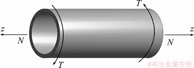
Figure 1 Schematic of loading model
 (1)
(1)
The following three loading paths are considered for reaching the final stress state in the plastic area, and the corresponding plastic strains  and
and  are then obtained.
1) Initial loading to ��z=��x along the z axis, the shear stress is increased to ����z=��x while keeping ��x unchanged.
2) Simple loading (proportional loading), the stress is increased to ��z=��x, ����z=��x=m��x according to the proportion ��z:����z=1:m.
3) The shear stress is increased to ����z=��x, and then the tensile stress is increased to ��z=��x while keeping ��x unchanged.
2.2 Determination of loading
After the stress state reaches the initial yield, the occurrence of plastic deformation in the materials due to the subsequent increment in the stress depends on whether the increase in the stress causes the loading of the material, i.e., whether
 The bias of stress state under each loading path can be expressed as follows:
 (2)
(2)
Hence,
 (3)
(3)
Using the Mises loading face  , it can be obtained that
  Consequently,
 (4)
(4)
Since ��z, d��z have the same sign, and ����z, d����z have the same sign, i.e.,  the material has been in the loading state after yielding.
2.3 Plastic deformation increment
Considering the orthogonal flow rule, Eqs. (2), and (4), we get:


 (5)
(5)

 (6)
(6)
3 Deduction of  and
and  under different stress paths
3.1 Space partition of (��x, ��x) stress
Because the integration interval of and
and is affected by the final stress values of ��x and ��x, the (��x, ��x) space is divided into four areas by making a vertical and a horizontal line perpendicular to the coordinate axes through the two intersection points of the initial yield surface and the coordinate axes. As shown in Figure 2, after partitioning, and is calculated in the areas I-IV according to paths A, B, and C, and the impact of different stress paths on the plastic strain is analyzed.
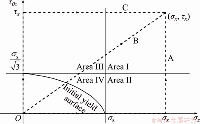
Figure 2 Space partition of  and diagram of stress path in area I
3.2 Section I (��x�ݦ�s,  , m>0)
3.2.1 Stress path A
When the applied axial stress is ��z=��s, the material yields after continuing to load, resulting in an axial plastic strain. After loading to ��x, then keeping ��z=��x unchanged, i.e., d��z=0, we apply torque to facilitate ����z=��x.
Using Eqs. (5) and (6), we get:

 (7)
(7)

 (8)
(8)
3.2.2 Stress path B
In the loading process,  d����z=md��z, and the material is loaded to
  When
When  the material begins to yield. Using Eqs. (5) and (6), we get:

 (9)
(9)

 (10)
(10)
3.2.3 Stress path C
When the applied shear stress is  , the material yields after continuing to load, resulting in a shear plastic strain. After loading to ��x, then keeping
  unchanged, i.e., d����z=0, we apply an axial force to facilitate ��z=��x.
Using Eqs. (5) and (6), we get:

 (11)
(11)

 (12)
(12)
3.2.4 Determination of tensile plastic strain
We construct a function:
 (13)
(13)
Substituting ��x=m��x in Eq. (13), we get:
 (14)
(14)
Taking partial derivative of Eq. (14) with respect to ��x and m, we obtain:
 (15)
(15)
 (16)
(16)
According to Eqs. (15) and (16), the function f 1 is monotonically increasing for both ��x and m. Since ��x�ݦ�s and m>0 in area I, it can be obtained that in the limit of ��x=��s and m��0, f 1 takes the
minimum value, and considering Eq. (14),  . However, in the area ��, m��0, so f 1>0 is always valid in the entire area I, namely,
 (17)
(17)
is always valid.
Construct a function:
 (18)
(18)
Substituting  in Eq. (18), we get:
 (19)
(19)
Taking partial derivative of Eq. (19) with respect to ��x and m, we obtain:
 (20)
(20)
 (21)
(21)
According to Eqs. (20) and (21), the function f2 is monotonically increasing for ��x and decreasing
for m . Since  and m>0 in area I, it can be obtained that in the limit of
  and
and  f 2 assumes the minimum value, and considering Eq. (19),
  However, in the area I, m cannot get positive infinity, so f2>0 is always valid in the entire area I, namely,
 (22)
(22)
is always valid.
3.2.5 Determination of shear plastic strain
Construct a function:

 (23)
(23)
Substituting ��x=m��x in Eq. (23), we obtain:
 (24)
(24)
Taking partial derivative of Eq. (24) with respect to ��x and m, we get:
 (25)
(25)
 (26)
(26)
According to Eqs. (25) and (26), the function f3 is monotonically decreasing for both ��x and m. Since ��x�ݦ�s and m>0 in the area I, it can be obtained that in the limit of ��x=��s and m��0, f3 takes the maximum value, and considering Eq. (24), we get  However, in the area I, m��0; so f3<0 is always valid in the entire area I, namely,
 (27)
(27)
is always valid.
Construct a function:

 (28)
(28)
Substituting in Eq. (28), we obtain:
 (29)
(29)
Taking partial derivative of Eq. (29) with respect to ��x and m, we get:
 (30)
(30)
 (31)
(31)
According to Eqs. (30) and (31), the function f4 is monotonically decreasing for ��x and increasing for m. Since and m>0 in the area I, it can be obtained that in the limit of and f4 assumes the maximum value, and considering Eq. (29), we get  . However, in the area I, m cannot get positive infinity, so f4<0 is always valid in the entire area I, namely,
 (32)
(32)
is always valid.
Combining Eqs. (17), (22), (27) and (32), we obtain that
 (33)
(33)
is always valid.
3.3 Section II (��x�ݦ�s,  ,
,  )
)
As shown in Figure 3, when the end point of stress ��(��x, ��x)�� is located in the area II, the final plastic strain under the three paths is calculated according to stress paths A, B, and C.
3.3.1 Stress paths A and B
The loading conditions of paths A and B in the area II are the same as those in the area I, and all of them satisfy ��x�ݦ�s. Thus, the expression of  ,
,  of path A in section II is the same as that of
 of path A in section I, and the expression of
 of path B in section II is the same as that of
 of path B in section I. It can be obtained that

 (34)
(34)
3.3.2 Stress path C
When the applied shear stress is  then keeping unchanged, i.e.,
  we apply an axial force. When the applied axial force is
  the loading continues and the material yields until it is loaded to
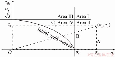
Figure 3 Space partition of (��x, ��x) and diagram of stress path in area II
Using Eqs. (5) and (6), we obtain:

 (35)
(35)

 (36)
(36)
3.3.3 Determination of tensile plastic strain
Construct a function:

 (37)
(37)
Substituting in Eq. (37), we obtain:

 (38)
(38)
Taking partial derivative of Eq. (38) with respect to ��x, we obtain 

When 

When 

When 

Taking partial derivative of Eq. (38) with respect to m, we obtain 

Construct a function  so that
  Therefore, g1(m) monotonically increases to m.
When  g1(m)=0, and then we obtain
When  g1(m)<0, and then we obtain
When  g1(m)>0, and then we obtain
From the above analysis, it can be concluded that the function f5 for ��x and m is first decreased and then increased, and the minimum value can be obtained when (��x, m) satisfies 
 Substituting
  in Eq. (38), we obtain
Since and 

 i.e.,
i.e.,  Since
Since  in Section II, we obtain
  However, ��x�ݦ�s in Section II, indicating that (��x, m) cannot satisfy
  Thus, f5>0 is always valid in Section II, namely,
 (39)
(39)
is always valid.
3.3.4 Determination of shear plastic strain
Construct a function,

 (40)
(40)
Substituting in Eq. (40), we get:
 (41)
(41)
Taking partial derivative of Eq. (41) with respect to ��x, we get 
Taking partial derivative of Eq. (41) with respect to m, we get 

Construct a function  so that
  Therefore, g2(m) monotonically decreases with m.
It can be concluded that the function f6 for ��x and m is first increased and then decreased,and the maximum value can be obtained when (��x, m) satisfies Substitutingin Eq. (41), we get 
Since and ��x=m��x,  i.e.,Since in Section II, we obtain However, ��x�ݦ�s in section II, indicating that (��x, m) cannot satisfy Thus, f6<0 is always valid in section II, namely,
 (42)
(42)
is always valid.
Combining Eqs. (34), (39) and (42), we obtain that
 (43)
(43)
is always valid.
3.4 Section �� (��s>��x>0, , 
As shown in Figure 4, when the end point of stress ��(��x, ��x)�� is located in the area III, the final plastic strain under the three paths is calculated according to the stress paths A, B, and C.
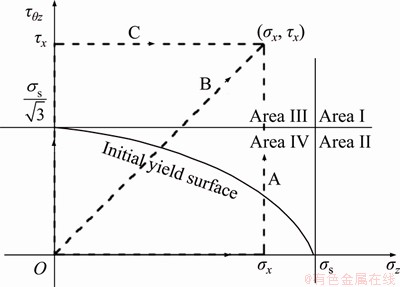
Figure 4 Space partition of (��x, ��x) and diagram of stress path in area III
3.4.1 Stress paths B and C
The loading conditions of paths B and C in area III are the same as those in area I, and all of them satisfy . Thus, the expression of 
 of path B in Section III is the same as that of
 of path B in Section I, and the expression of
 of path C in Section III is the same as that of
 of path C in section I. Therefore, it can be obtained that

 (44)
(44)
is always valid.
3.4.2 Stress path A
When the applied axial stress is ��z=��x, then keeping ��z=��x unchanged, i.e., d��z=0, we apply a torque. When the applied torque is  the loading is continued and the material yields until it is loaded to ����z=��x.
Using Eqs. (5) and (6), we get:

 (45)
(45)

 (46)
(46)
3.4.3 Determination of tensile plastic strain
Construct a function:
 (47)
(47)
Substituting ��x=m��x in Eq. (47), we obtain:
 (48)
(48)
Taking partial derivative of Eq. (48) with respect to ��x, we obtain  . Further, the partial derivative of Eq. (48) with respect to m is
It can be concluded that the function f7 for ��x and m is first decreased and then increased,and the minimum value can be obtained when (��x, m) satisfies
 Substituting
  in Eq. (48), we obtain
Since and 
 i.e.,
i.e.,  As
As  in Section III, and
  monotonically increases with m, we obtain
  However, in Section III, indicating that (��x, m) cannot satisfy
  Thus, f7>0 is always valid in the entire Section III, namely,
 (49)
(49)
is always valid.
3.4.4 Determination of shear plastic strain
Construct a function:


 (50)
(50)
Substituting ��x=m��x in Eq. (50), we get:

 (51)
(51)
Taking partial derivative of Eq. (51) with respect to ��x, we get 
 Similarly, the partial derivative of Eq. (51) with respect to m is
It can be concluded that the function f8 for ��x and m is first increased and then decreased,and the maximum value can be obtained when (��x, m) satisfies Substituting in Eq. (51), we get 
Since and i.e., As in Section III and is monotonically increasing for m, we obtain  . Further, in Section III, indicating that (��x, m) cannot satisfy Thus, f8<0 is always valid in the entire Section III, namely,
 (52)
(52)
is always valid.
Combining Eq. (44), (49) and (52), we obtain that
 (53)
(53)
is always valid.
3.5 Section IV (��s>��x>0,  , m>0)
As shown in Figure 5, when the end point of stress ��(��x, ��x)�� is located in the area IV, the final plastic strain under the three paths is calculated according to the stress paths A, B, and C.
The loading conditions of paths A and B in Section IV are the same as those in Section III, and all of them satisfy ��s>��x>0. Therefore, the expression of 
 of path A in Section IV is the same as that of
 of path A in Section III, and the expression of
 of path B in Section IV is the same as that of
  of path B in Section III. It can be directly obtained that:

 (54)
(54)
is always valid.
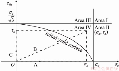
Figure 5 Space partition of (��x, ��x) and diagram of stress path in area IV
The loading conditions of paths B and C in Section IV are the same as those in Section II. Moreover, all of them satisfy  Therefore, the expression of
 of path B in Section IV is the same as that of
 of path B in Section II, and the expression of
 of path C in Section IV is the same as that of
 of path C in Section II, respectively. It can be directly obtained that

 (55)
(55)
is always valid.
Combining Eqs. (54) and (55), we infer that
 (56)
(56)
is always valid.
3.6 Correlation of  and
and  under different stress paths
Combining Eqs. (33), (43), (53) and (56), it can be inferred that the following expressions of and under different stress paths are always valid:
 (57)
(57)
According to Eq. (57), under different stress paths, if tensile stress is applied first followed by shear stress (stress path A), the corresponding tensile strain is the largest strain among the three stress paths. If shear stress is applied first followed by tensile stress (stress path C), the corresponding shear strain is the largest strain among the three stress paths. When proportional loading (stress path B) is implemented, the final tensile strain and shear strain lie between the strain results of paths A and C. Irrespective of the position of the final stress state in the plastic area, under the combined action of tension and torsion, the order of stress application has a significant impact on the composition of the final plastic strain, and the effect of first applied stress is more obvious in the final plastic strain, which is similar to the ��preconceived�� effect in life. This implies that the stress path has a primary effect on the plastic strain. The primary effect is not only applicable to specific stress states in Ref. [27] but also to all the stress states located in the plastic area.
4 Discussion
4.1 Recency effect based on strain path
XU et al [28] proposed an analytical solution for stress after reaching a specific strain state through three specific strain paths. It can be found that under different strain paths, if tensile strain is applied first, followed by shear strain (strain path A), the corresponding shear stress is the largest stress among the three strain paths; if shear strain is applied first, followed by tensile strain (strain path C), the corresponding tensile stress is the largest stress among the three strain paths. Under proportional loading (strain path B), the final tensile stress and shear stress lie between the stress results of paths A and C.
To verify the applicability of this relation in the entire plastic area, it is assumed that the strain state (��x, ��x) of the plastic area is reached through three strain paths, which are as follows: A is first loaded with tensile strain and then with shear strain, B undergoes proportional loading, and C is first loaded with shear strain and then with tensile strain. Through stringent calculations, it can be obtained that �� and �� satisfy the following condition under different strain paths:
 (58)
(58)
The rule: ��post-loaded strain has a stronger effect on the final stress under different strain paths�� is generally applicable, which is similar to the ��recency effect�� in psychology.
4.2 Consistency of primary and recency effects
For isotropic linearly hardened materials that satisfy the Mises yield condition, stress path has the primary effect on plastic strain; while strain path exhibits recency effect on the stress results. Consequently, it must be investigated whether the primary effect is contradictory to the recency effect.
First, stress path A (tensile stress is applied first, followed by shear stress) is analyzed, and the nominal deformation modulus is defined as E=��/��. Because final tensile stress �� is constant and the primary effect exists in this case, the tensile strain ��p1 corresponding to the first applied tensile stress is the maximum among the three stress paths, so the corresponding nominal deformation modulus E is the minimum. This implies that the first applied stress has a smaller nominal deformation modulus. For strain path A (tensile strain is applied first, followed by shear strain), since the final tensile strain �� is fixed and the recency effect exists in this case, the tensile stress ��1 corresponding to the first applied tensile strain is the minimum among the three strain paths, so the corresponding nominal deformation modulus E is also the minimum. From the perspective of the deformation modulus, the effects of stress path A and strain path A on the deformation are similar.
The stress path C (shear stress is applied first, followed by tensile stress) is analyzed, and the nominal shear deformation modulus is defined as G=��/��. Because the final shear stress �� is fixed and the primary effect exists, the shear strain ��p3 corresponding to the first applied shear stress is the maximum among the three stress paths, so the corresponding nominal shear deformation modulus G is the minimum. This implies that the first applied stress has a smaller nominal shear deformation modulus. For strain path C (shear strain is applied first, followed by tensile strain), since the end shear strain �� is constant and the recency effect exists, the corresponding shear stress ��3 of the first applied shear strain is the smallest in the three strain paths, so the corresponding nominal shear deformation modulus G is the also the minimum. From the perspective of shear deformation modulus, the effects of stress path C and strain path C on deformation are consistent.
For proportional loading (stress path B and strain path B), the nominal deformation modulus lies between loading paths A and C.
To recapitulate, from the perspective of deformation, the primary effect of stress path and the recency effect of strain path are dialectically unified. The pre-loaded stress or strain has a corresponding smaller deformation (shear) modulus, while the post-loaded stress or strain has a larger deformation (shear) modulus. Further, the effects of stress path and strain path can be unified as the recency effect of loading path on the nominal deformation modulus. This implies that irrespective of whether it is stress loading or strain loading, the material is less resistant to the pre-loaded stress or strain, and is more prone to deformation, while it is more resistant to post-load stress or strain. Based on the physical mechanism, both the primary and recency effects are direct results of material strengthening.
4.3 Potential applications of primary and recency effects
Facilitated by the psychological terms, the complex loading path effect is closely related to the familiar primary and recency effects, which play a crucial role in the teaching practice of elastoplasticity. This simplification of complex problems can help the students to quickly judge the accuracy of the results of stress path or strain path, thereby strengthening their understanding of the impact of loading path on plastic deformation.
Examples of loading paths with a significant impact on a project are often encountered. For isotropic Mises materials, the recency effect is both simple and universal, and is a highly generalized law. The rules of primary and recency effects can be generalized to many engineering materials and have good application prospects.
To prove these application prospects, we designed a thin-walled tube for tensile test, as shown in Figure 6. This thin-walled tube was composed of 304 stainless steel, which is a common engineering material. The stress-strain curve obtained through the tensile test is shown in Figure 7. This curve is consistent with the ��bilinear isotropic hardening�� in classical theory, and the linear strengthening characteristic is obvious. This indicates that the classic Mises yield criterion and isotropic linear hardening assumption are consistent with the materials used in engineering practices. Therefore, the primary and recency effects based on the classic Mises yield criterion and the isotropic linear hardening hypothesis are not overly idealized theories but can be applied to practical engineering materials and have good application prospects. However, it must be studied whether this law can be extended to more general situations, such as non-linearly hardened materials or even more complex geotechnical materials.
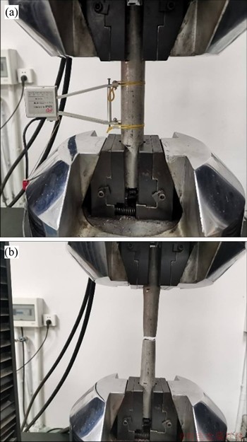
Figure 6 Tensile test of a thin-walled tube composed of 304 stainless steel
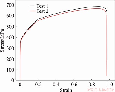
Figure 7 Stress-strain curve of thin-walled tube composed of 304 stainless steel
For more complicated engineering problems, such as foundation pit excavation, pit side loading, tunneling in high-stressed rock mass, dynamic response to earthquake, the behavior of materials shows even more obvious loading path effect. However, the existence of primary and recency effects for these problems needs further exploration.
5 Conclusions
We analyzed the effect of loading path in the elastoplastic tensile and torsional problem of thin-walled circular tube in an isotropic linearly hardened material based on the classical elastoplasticity. Further, the plastic stress-strain relation under different loading paths was deduced, and the impact of loading path on deformation was examined. The main results of the study can be summarized as follows:
1) Under different stress paths, the corresponding strain caused by the pre-loaded stress is the largest in the final plastic strain state, and the stress path has the primary effect on the plastic strain.
2) Under different strain paths, the corresponding stress caused by the post-loaded strain is the largest in the final stress result, and the strain path has the recency effect on the stress results.
3) From the perspective of deformation, the primary effect of stress path on the plastic strain and the recency effect of strain path on the stress result are unified, which can be uniformly expressed as the recency effect of the loading path on the nominal deformation modulus. This implies that the material is more resistant to post-loaded stress or strain.
4) The primary and recency effects of the loading path exhibit immense potential for obtaining a deep understanding of the stress-strain relation in classical plasticity. Further, in the engineering field, they can serve as a useful reference for optimizing the design scheme and for improving the construction process.
Nomenclature

Axial plastic strain

Tangential plastic strain

Axial plastic strain of path B in area I

Tangential plastic strain of path C in area II
��p
Cumulative plastic strain
��z
Normal stress, MPa
����z
Shear stress, MPa
��x
Normal stress at the end point of stress, MPa
��x
Shear stress at the end point of stress, MPa
��s
Yield stress, MPa
��
Equivalent stress, MPa
sx/y/x
Bias of the stress state, MPa
J2
Second invariant of bias stress, MPa2
h
Plastic modulus, GPa
E
Elastic modulus, GPa
G
Shear modulus, GPa
��
Poisson ratio
Contributors
GAO Yue provided the concept and wrote the first draft of the manuscript. SHAO Fei edited the draft of manuscript and provided funding for the research. FAN Peng-xian derived part of the formula of the article and edited the draft of manuscript. XU Qian edited the draft of manuscript.
Conflict of interest
GAO Yue, SHAO Fei, FAN Peng-xian and XU Qian declare that they have no conflict of interest.
References
[1] ZHAN Qi-sheng, YU Zhi-hui. Comparison of the effects of primary effect and recency effect in different contexts [J]. Journal of Health Psychology, 2000, 8(3): 251-253. DOI: 10.13342/j.cnki.cjhp.2000.03.005. (in Chinese)
[2] BADDELEY A D, HITCH G. The recency effect: Implicit learning with explicit retrieval [J]. Memory & Cognition, 1993, 21(2): 146-155. DOI: 10.3758/bf03202726.
[3] FOLKE O, PERSSON T, RICKNE J. The primary effect: Preference votes and political promotions [J]. American Political Science Review, 2016, 110(3): 559-578. DOI�� 10.1017/S0003055416000241.
[4] LI Zhen, ZHOU Hui, JIANG Yue, HU Da-wei, ZHANG Chuan-qing. Methodology for establishing comprehensive stress paths in rocks during hollow cylinder testing [J]. Rock Mechanics and Rock Engineering, 2019, 52(4): 1055-1074. DOI: 10.1007/s00603-018-1628-5.
[5] WANG Le-hua, NIU Cao-yuan, ZHANG Bing-wei, MA Yun-biao, YIN Si-jie, XU Xiao-liang. Experimental study on mechanical properties of deep-buried soft rock under different stress paths [J]. Chinese Journal of Rock Mechanics and Engineering, 2019, 38(5): 973-981. DOI: 10.13722/ j.cnki.jrme.2018.0973. (in Chinese)
[6] LIM A, OU C Y. Stress paths in deep excavations under undrained conditions and its influence on deformation analysis [J]. Tunnelling and Underground Space Technology, 2017, 63: 118-132. DOI: 10.1016/j.tust.2016.12.013.
[7] WANG Jiang-ying, CAO Wen-gui, JIANG Zhong-ming, ZHAO Zhi-peng. Large-scale triaxial test study on deformation mechanical properties of soil-rock mixture under different stress paths [J]. Rock and Soil Mechanics, 2016, 37(2): 424-430. DOI: 10.16285/j.rsm.2016.02.015. (in Chinese)
[8] KAWALKO J, MUSZKA K, GRACA P, KWIECIEN M, SZYMULA M, MARCISZKO M, BALA P, BEYERLEIN I J. The effect of strain path changes on texture evolution and deformation behavior of Ti6Al4V subjected to accumulative angular drawing [J]. Materials Science and Engineering A, 2019, 764: 138168. DOI: 10.1016/j.msea.2019.138168.
[9] TANG Long-qing, JIANG Fu-lin, TENG Jie, FU Ding-fa, ZHANG Hui. Strain path dependent evolutions of microstructure and texture in AZ80 magnesium alloy during hot deformation [J]. Journal of Alloys and Compounds, 2019, 806: 292-301. DOI: 10.1016/j.jallcom.2019.07.262.
[10] BAI Qing-sheng, YOUNG R. Numerical investigation of the mechanical and damage behaviors of veined gneiss during true-triaxial stress path loading by simulation of in situ conditions [J]. Rock Mechanics and Rock Engineering, 2020, 53(1): 133-151. DOI: 10.1007/s00603-019-01898-2.
[11] QI Zhen-jie, XIA Qin-xiang, QI Chun-xiao, QIU Zun-wen. Numerical simulation analysis of forming high strength steel sheet under different strain paths [J]. Forging Technology, 2013, 38(1): 35-39. DOI: 10.3969/j.issn.1000-3940.2013.01. 008. (in Chinese)
[12] LI Dong-wei, CHEN Jun-hao, ZHOU Yan. Triaxial shear test and constitutive model of artificial frozen soil with complicated stress path [J]. China Coal Journal, 2016, 41(S2): 407-411. DOI: 10.13225/j.cnki.jccs.2014.1347. (in Chinese)
[13] TAHERI-BEHROOZ F, KIANI A. Numerical investigation of the macroscopic mechanical behavior of NiTi-Hybrid composites subjected to static load�Cunload�Creload path [J]. Journal of Materials Engineering and Performance, 2017, 26(4): 1483-1493. DOI: 10.1007/s11665-017-2574-1.
[14] ZHU Nan, LIU Chun-yuan, ZHAO Xian-hui, WANG Wen-jing. Experimental study on microstructure characteristics of K_(0) consolidated structural clay under different stress paths [J]. Rock and Soil Mechanics, 2020, 41(6): 1-12. DOI: 10.16285/j.rsm.2019.1558. (in Chinese)
[15] GUO Yu-liang, CAO Li-wen, HUO Pan. Study on the strength and microstructure of unsaturated polluted soil under two stress paths [J]. Journal of Applied Basics and Engineering Science, 2019, 27(3): 602-611. DOI: 10.16058/ j.issn.1005-0930.2019.03.012. (in Chinese)
[16] GUPTA A, KHATIRKAR R K, KUMAR A, THOOL K, BIBHANSHU N, SUWAS S. Microstructure and texture development in Ti-15V-3Cr-3Sn-3Al alloy��Possible role of strain path [J]. Materials Characterization, 2019, 156: 109884. DOI: 10.1016/j.matchar.2019.109884.
[17] CHEN Jia-quan, CHEN Guo-jun, WEN Jie-ming. Multiaxial low cycle fatigue life prediction model considering strain paths [J]. Engineering Mechanics, 2012, 29(4): 84-89. (in Chinese)
[18] EGLY T A, LANG K H, LOHE D. Influence of phase shift and strain path on the thermomechanical fatigue behavior of CMSX-4 specimens [J]. International Journal of Fatigue, 2007, 30(2): 249-256. DOI: 10.1016/j.ijfatigue.2007.01.035.
[19] ITOH T, NAKATA T, SAKANE M, OHNAMI M. Nonproportional low cycle fatigue of 6061aluminum alloy under 14 strain paths [J]. European Structural Integrity Society, 1999, 25: 41-54. DOI: 10.1016/S1566-1369(99) 80006-5.
[20] QIAN Jian-gu, DU Zi-bo, LU Xi-lin, GU Xiao-qiang, HUANG Mao-song. Effects of principal stress rotation on stress�Cstrain behaviors of saturated clay under traffic�Cload�C induced stress path [J]. Soils and Foundations, 2019, 59(1): 41-55. DOI: 10.1016/j.sandf.2018.08.014.
[21] SCHWARZ S, MAUTE K, RAMM E. Topology and shape optimization for elastoplastic structural response [J]. Computer Methods in Applied Mechanics and Engineering. 2001, 190(15-17): 2135-2155. DOI: 10.1016/s0045-7825 (00)00227-9.
[22] JANIK M, DYJA H, BERSKI S, BANASZEK G. Two- dimensional thermomechanical analysis of continuous casting process [J]. Journal of Materials Processing Technology, 2004, 153-154: 578-582. DOI: 10.1016/ j.jmatprotec.2004.04.129.
[23] CERMAK M, KOZUBEK T, SYSALA S, VALDMAN J. A TFETI domain decomposition solver for elastoplastic problems [J]. Applied Mathematics and Computation, 2014, 231: 634-653. DOI: 10.1016/j.amc.2013.12.186.
[24] ARTIOLI E, AURICCHIO F, BEIRAO DA VEIGA L. A novel ��optimal�� exponential-based integration algorithm for von-Mises plasticity with linear hardening: Theoretical analysis on yield consistency, accuracy, convergence and numerical investigations [J]. International Journal for Numerical Methods in Engineering, 2006, 67(4): 449-498. DOI: 10.1002/nme.1637.
[25] SZABO L. A semi-analytical integration method for J2 flow theory of plasticity with linear isotropic hardening [J]. Computer Methods in Applied Mechanics and Engineering, 2009, 198(27-29): 2151-2166. DOI: 10.1016/j.cma.2009. 02.007.
[26] SAHIN S, TOPARLI M, OZDEMIR I, SASAKI S. Modelled and measured residual stresses in a bimaterial joint [J]. Journal of Materials Processing Technology, 2003, 132(1): 235-241. DOI: 10.1016/s0924-0136(02)00932-9.
[27] CHEN Ming-xiang. Elasticity and plasticity [M]. Beijing: Science Press, 2007. (in Chinese)
[28] XU Bing-ye, LIU Xin-sheng. Applied elastoplastic mechanics [M]. Beijing: Tsinghua University Press, 1995. (in Chinese)
(Edited by ZHENG Yu-tong)
���ĵ���
����������ѧ�м���·��Ӱ��ġ�����ЧӦ���͡�����ЧӦ��
ժҪ��Ϊ̽������·����Ӱ����ɣ�����Mises���������͵�������Ӳ�����裬��������������Ť�����������²���ѹ������Բ�ܵĵ����Է���ģ�ͣ������յ�Ӧ�����ص㻮����4��(��x����x)Ӧ�������Ƶ��˲�ͬӦ��������12��Ӧ��·��������Ӧ��-Ӧ���ϵ��֤����Ӧ��·��������Ӧ��Ӱ��ġ�����ЧӦ�������������յ�Ӧ�����ںδ����������õ�Ӧ�����������Ա������Ǹ����ھ��䵯�������۷�����Ӧ��·����Ӱ�죬������Ӧ��·����Ӧ�����Ӱ��ġ�����ЧӦ������������ص�Ӧ�������յ�Ӧ��״̬�в�����Ӱ����ӱ��εĽǶȣ�Ӧ��·��������Ӧ��Ӱ��ġ�����ЧӦ����Ӧ��·����Ӧ�����Ӱ��ġ�����ЧӦ����ͳһ�ġ���ЧӦ�������������ԣ�����ѧϰ���ⲻͬ����·���µ�����Ӧ��-Ӧ���ϵ�������棬�����Ż��ӹ����պ�ʩ������Ҳ����һ����ָ�����á�
�ؼ��ʣ���������Ӳ����Ӧ��·����Ӧ��·��������ЧӦ������ЧӦ
Foundation item: Project(51979280) supported by the National Natural Science Foundation of China; Projects(2016M602972, 2018M643852) supported by the Postdoctoral Science Foundation of China
Received date: 2020-03-05; Accepted date: 2020-06-28
Corresponding author: SHAO Fei, PhD, Professor; Tel: +86-13951798458; E-mail: shaofei@seu.edu.cn; ORCID: https://orcid.org/0000- 0002-7165-9967; FAN Peng-xian, PhD, Associate Professor; Tel: +86-18936890687; E-mail: fan-px@139.com; ORCID: https://orcid.org/0000-0002-1195-4884

