
Shot lining of magnesium alloy with hard powders
Y. HARADA1, I. FUKUDA2
1. Graduate School of Engineering, University of Hyogo, Kamigohri Akoh Hyogo 678-1297, Japan;
2. Yatsushiro National College of Technology, Yatsushiro, Kumamoto 866-8501, Japan
Received 23 September 2009; accepted 30 January 2010
Abstract: To improve the surface properties, lining of magnesium alloys with hard powders by shot peening was carried out in order. The hard powders were tried to bond to the workpiece surface due to the collision of many shots. In order to fix the hard powders to the surface of the workpiece, the powders were set on an uneven surface. To easily facilitate fixing of powders, lining of the workpiece with the powder sandwiched between two aluminum foil sheets was also attempted. In this experiment, a centrifugal shot peening machine with an electrical heater was employed. The workpieces were magnesium alloys AZ31B and AZ91D, and the hard powders were commercial cemented carbide, alumina, and zirconia. The joinability of hard powders near the lined surface was observed by a optical microscope. The wear resistance was also evaluated by a wear test. The hard powders were successfully bonded to the surface of workpieces by the shot lining process. The results show that the present method is effective in wear resistance of the magnesium alloys.
Key words: shot peening; surface treatment; lining; joining; joinability; magnesium alloy; hardness; wear resistance; cemented carbide; ceramic
1 Introduction
Magnesium and its alloys are used widely in industry because of excellent properties such as light weight and high specific tensile strength[1-3]. However, the application is still limited because the wear resistance of magnesium products is not nearly as good as steel in ambient and high temperatures. Therefore, there is a strong demand to improve the surface treatment that can guarantee the wear resistance of the part in the aggressive atmosphere environment. In general, surface treatments are used to improve the surface properties such as wear resistance and corrosion resistance. There are many lining processes, such as plating[4], PVD and CVD[5-6]. Also, the bonding processes are utilized in many of metal forming[7]. On the other hand, the authors proposed a lining process of metals with thin foils using shot peening[8-11]. In this method, the foil can be bonded to the workpiece surface to bring about large plastic deformation. The pressure generated by the hit of many shots is utilized for the bonding. The lining process using shot peening, i.e. shot lining, is very suitable for the bonding of thin and dissimilar foils.
In the present study, the lining of magnesium alloy with hard powders by the shot peening process was investigated. The hard powders were bonded to the workpiece surface by the collision of many shots. The joinability of hard powders near the lined surface was observed in the optical microscope. The workpiece surface lined by hard powder was also examined by a wear test.
2 Experimental
2.1 Lining of hard powders
In the shot lining process, it is very difficult to bond the hard material. In the present study, by using the powder of hard material such as cemented carbide and ceramic, the lining of magnesium alloy with hard powders was tried. The hard powders were bonded to the surface by the collision of many shots. The powders are set on an uneven surface as shown in Fig.1. The uneven surface was treated by shot peening. The pure aluminium foil was used to prevent the air pressure generated by a rotary wheel of peening machine and the contamination of dust in the air chamber.
2.2 Modified lining of hard powders
In order to simplify the fixing of hard powders, the lining of the workpiece with sandwich foil shown in Fig.2 was tried. In the modified method, the hard powders

Fig.1 Lining of workpiece with hard powders by shot peening
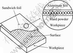
Fig.2 Lining of workpiece with sandwich foil by shot peening
were sandwiched between two pure aluminium foils by a press. The aluminium foil used was about 0.015 mm in thickness. The sandwich foil is easy to be used for lining.
2.3 Shot peening and materials
A centrifugal shot peening machine was employed in the experiment. The hard powders are cemented carbide, Al2O3 and ZrO2. The workpieces are magnesium AZ31B and AZ91D. To make the bonding easy, the hard powders and workpiece were heated in air by using an electric furnace. The shots used for the lining are made of the high-carbon cast steel and the shot diameter is 1.0 mm. The lining experiment was performed at 300 ?C at an impact velocity of 80 m/s.
The method of lining of the hard powders is shown in Fig.3. The workpieces surface was cleaned with emery

Fig.3 Lining of workpiece with aluminium foil by using masking plate
papers. The lining range is limited by the mask plate. As the cover foil, pure aluminium foil is slightly larger than the mask plate and is fixed for the collision by the plate. The margin of the foil for the fixation is about 5 mm.
2.4 Wear test
To evaluate the wear resistance for the lined surface, wear test was conducted. A cylindrical grinding wheel removed a layer of material under a certain load, as shown in Fig.4. The workpiece was held in place with a chuck. The size of abrasive grain was about 0.2 mm. The experiment was performed in a wet atmosphere in order to prevent the friction heat.
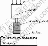
Fig.4 Experimental equipment for wear test by using grinding wheel
3 Results and discussion
3.1 Appearance of lined workpiece
The lining of magnesium alloy with hard powders was performed by shot peening. The lined surface of workpieces is shown in Fig.5. The workpieces are AZ31B (a) and AZ91D (b). The pure aluminium foil was
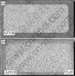
Fig.5 Appearances of lined magnesium alloys after shot peening: (a) Workpiece AZ31B with cemented carbide powders; (b) Workpiece AZ91D with alumina powders
successfully bonded to the workpiece. Therefore, the hard powders were also bonded to the workpiece.
3.2 Micrograph of lined workpiece
The microscopic photographs of cross-section for magnesium alloy AZ31B and hard powders, magnesium alloy AZ91D and hard powders are shown in Fig.6 and Fig.7, respectively. The hard powders were successfully bonded to the workpiece. There are no voids and cracks. However, it is very difficult to measure the bond strength between the workpiece and powder. In this study, the lined workpieces were bent until the cracks occur. Although cracks were generated on the surface, the separation from the surface was not observed. Thus, the bond strength of the powder was sufficient.

Fig.6 Micrographs of cross-sections of magnesium alloys AZ31B with different hard powders: (a) Cemented carbide; (b) Alumina; (c) Zirconia
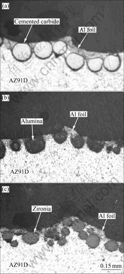
Fig.7 Micrographs of cross-sections of magnesium alloys AZ91D with different hard powders: (a) Cemented carbide; (b) Alumina; (c) Zirconia
3.3 Micrograph of lined workpiece by using sandwich foil
Since it is difficult to fix the hard powders on the workpiece with the smooth surface, the powders are set on the uneven surface. However, it is not easy to fix the powder in the case of the workpiece with a curved surface. These workpieces require special surface treatments to fix powders. To simplify the fixing of powders, the lining process of workpiece with sandwich foil was attempted. The microscopic photographs of cross-section for magnesium alloys and sandwich foil are shown in Fig.8. The foil used for the sandwich was a pure aluminum foil of 0.015 mm in thickness. The sandwich foil was successfully bonded to the workpiece. There were no voids and cracks around the powders.

Fig.8 Micrographs of cross-sections of magnesium alloys with different hard powders using sandwich foil: (a) Cemented carbide/AZ31B; (b) Zirconia/AZ31B; (c) Cemented carbide/ AZ91D
3.4 Wear resistance
Wear test by using grinding wheel was examined. The surfaces of the lined workpieces after the wear test are given in Fig.9. The workpiece was magnesium alloy AZ31B. The equipment used for wear test imposes a load of 19.6 N on a 6 mm diameter wheel. The grinding time was about 10 s. The surface of the workpiece with the sandwich foil was uniformly hit with many shots (Fig.9(a)). The exfoliation of the sandwich foil from the surface of the workpiece was not observed. The surface of lined workpiece in Fig.9(c) shows good wear resistance. However, the surface of the un-lined workpiece in Fig.9(b) exhibits a flat substrate by grinding. Thus, the lined workpiece provides excellent wear resistance.
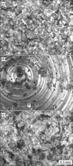
Fig.9 Surface of lined AZ31B workpieces after grinding: (a) No-grinding of lined workpiece; (b) Grinding of un-lined workpiece; (c) Grinding of lined workpiece
To evaluate the wear resistance for the lined surface, the depth of wear was measured. The variation of the ratio of depth of wear with processing time is given in Fig.10, where the ratio of depth of wear is defined as the depth of wear divided by an initial thickness of workpiece. The workpiece was magnesium alloy AZ31B. The ratio of depth of wear increases with the processing time. In the case of the lining of workpiece with the cemented carbide and alumina powders, the ratio is smaller. Namely, the lined surface has a fairly good resistance to wear.
The wear test was examined by changing magnesium alloy workpiece. The variation of the ratio of depth of wear with processing time is given in Fig.11. The wear resistance for the lined workpieces is nearly the same as the magnesium alloy AZ31B workpieces.

Fig.10 Variation of ratio of depth of wear vs time for magnesium alloy AZ31B
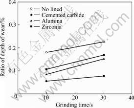
Fig.11 Variation of ratio of depth of wear vs time for magnesium alloy AZ91D
4 Conclusions
1) Lining of hard powders by using the shot peening process was investigated in order to improve the surface characteristics of magnesium alloy.
2) The hard powders could be successfully bonded to the workpieces by the hit of shots. To simplify the fixing of powders, the lining of sandwich foil with the hard powders was also tried. The sandwich foil including the hard powders was also bonded to the surface.
3) The wear resistance of the lined workpiece was confirmed to be sufficient by a wear test of lined workpieces. The present method using shot peening was effective in wear resistance of the magnesium alloys.
Acknowledgement
We would like to thank Mr. H. Kosugi for valuable discussions. This research was supported in part by a grant from The Light Metal Educational Foundation, Inc.
References
[1] MARTIN A, LLORCA J. Mechanical behaviour and failure mechanism of a binary Mg-6%Zn alloy reinforced with SiC particulates [J]. Mater Sci Eng A, 1995, 201: 77-87.
[2] WATANABE H, TSUYSUI H, MUKAI T, KOHZU M, TANABE S, HIGASHI K. Deformation mechanism in a coarse-grained Mg-Al-Zn alloy at elevated temperatures [J]. International Journal of Plasticity, 2001, 17: 387-397.
[3] PODDAR P, SRIVASTAVA V C, DE P K, SAHOO K L. Processing and mechanical properties of SiC reinforced cast magnesium matrix composites by stir casting process [J]. Mater Sci Eng A, 2007, 460/461: 357-364.
[4] AMBAT R, ZHOU W. Electroless nickel-plating on AZ91D magnesium alloy: Effect of substrate microstructure and plating parameters [J]. Surface and Coatings Technology, 2004, 179: 124-134.
[5] HOCHE H, ROSENKRANZ C, DELP A, LOHRENGEL M M, BROSZEIT E, BERGER C. Investigation of the macroscopic and microscopic electrochemical corrosion behaviour of PVD-coated magnesium die cast alloy AZ91 [J]. Surface and Coatings Technology, 2005, 193(1/3): 178-184.
[6] YAMAUCHI N, DEMIZU K, UEDA N, SONE T, TSUJIKAWA M. Effect of peening as pretreatment for DLC coatings on magnesium alloy [J]. Thin Solid Films, 2006, 506/507: 378-383.
[7]MATSUMOTO H, WATANABE S, HANADA S. Fabrication of pure Al/Mg-Li alloy clad plate and its mechanical properties [J]. Journal of Materials Processing Technology, 2005, 169(1): 9-15.
[8] HARADA Y, TSUCHIDA N, FUKAURA K. Joining and shaping fit of dissimilar materials by shot peening [J]. Journal of Materials Processing Technology, 2006, 177: 356-359.
[9] HARADA Y, FUKAURA K, KIM D. Lining of carbon steel with metal foils by shot peening [J]. Materials Science Forum, 2007, 561/565: 853-856.
[10] HARADA Y, FUKAURA K. Plastic flow joining by shot peening [J]. Key Engineering Materials, 2007, 340/341: 865-870.
[11] HARADA Y. Caulking of dissimilar materials using shot peening [J]. Journal of Solid Mechanics and Materials Engineering, 2007, 1-4: 529-538.
(Edited by LIU Hua-sen)
Corresponding author: Y. HARADA; Tel: +81-79-267-4906; Fax: +81-79-267-4885; E-mail: harada@eng.u-hyogo.ac.jp

