Numerical analysis of tunnel reinforcing influences on failure process of surrounding rock under explosive stress waves
来源期刊:中南大学学报(英文版)2008年第5期
论文作者:左宇军 唐春安 朱万成 李地元 李术才
文章页码:632 - 632
Key words:tunnel reinforcing; numerical simulation; explosive stress wave; failure process; inhomogeneity
Abstract: Based on mesoscopic damage mechanics, numerical code RFPA2D (dynamic edition) was developed to analyze the influence of tunnel reinforcing on failure process of surrounding rock under explosive stress waves. The results show that the propagation phenomenon of stress wave in the surrounding rock of tunnel and the failure process of surrounding rock under explosive stress waves are reproduced realistically by using numerical code RFPA2D; from the failure process of surrounding rock, the place at which surrounding rock fractures is transferred because of tunnel reinforcing, and the rockfall and collapse caused by failure of surrounding rock are restrained by tunnel reinforcing; furthermore, the absolute values of peak values of major principal stress, and the minimal principal stress and shear stress at center point of tunnel roof are reduced because of tunnel reinforcing, and the displacement at center point of tunnel roof is reduced as well, consequently the stability of tunnel increases.
基金信息:the National Natural Science Foundation of China
Major State Basic Research Development Program of China
Postdoctoral Science Foundation of China
J. Cent. South Univ. Technol. (2008) 15: 632-638
DOI: 10.1007/s11771-008-0118-4
![]()
ZUO Yu-jun(左宇军)1, 2, TANG Chun-an(唐春安)3, ZHU Wan-cheng(朱万成)2,
LI Di-yuan(李地元)4, LI Shu-cai(李术才)5
(1. Research Center for Numerical Test of Material Failure, Dalian University, Dalian 116622, China;
2. Center for Rock Instability and Seismicity Research, Northeastern University, Shenyang 110004, China;
3. School of Civil and Hydraulic Engineering, Dalian University of Technology, Dalian 116024, China;
4. School of Resources and Safety Engineering, Central South University, Changsha 410083, China;
5. Geotechnical and Structural Engineering Research Center, Shandong University, Jinan 250061, China)
Abstract: Based on mesoscopic damage mechanics, numerical code RFPA2D (dynamic edition) was developed to analyze the influence of tunnel reinforcing on failure process of surrounding rock under explosive stress waves. The results show that the propagation phenomenon of stress wave in the surrounding rock of tunnel and the failure process of surrounding rock under explosive stress waves are reproduced realistically by using numerical code RFPA2D; from the failure process of surrounding rock, the place at which surrounding rock fractures is transferred because of tunnel reinforcing, and the rockfall and collapse caused by failure of surrounding rock are restrained by tunnel reinforcing; furthermore, the absolute values of peak values of major principal stress, and the minimal principal stress and shear stress at center point of tunnel roof are reduced because of tunnel reinforcing, and the displacement at center point of tunnel roof is reduced as well, consequently the stability of tunnel increases.
Key words: tunnel reinforcing; numerical simulation; explosive stress wave; failure process; inhomogeneity
1 Introduction
Stability and deformation of surrounding rock in underground engineering are always two very important topics during design and construction[1]. In order to prevent from occurrence of rockfall and collapse, and to increase stability of tunnel or cave, many methods, such as bolt reinforcing, shotcrete supporting, or combination of them, are used to reinforce tunnel and cave. Which kind of method to be used is determined based on specified cases of engineering, and not the same pattern of reinforcing is used in all engineering. So far, many researches on stability and failure of tunnel in rock mass under static loading have been studied[2]. However, a real tunnel is usually influenced by dynamic loading, such as blasting, rock burst, earthquake and periodic ground pressure, thereinto blasting vibration is a main factor causing impact ground pressure of surrounding rock of tunnel. Therefore, it has very important realistic sense to study the stability of surrounding rock under blasting loading[3-5]. Now some researches on instability of surrounding rock of tunnel induced by vibration such as blasting etc have been paid attention to by scholars[6-12]. Moreover, correlative analysis has been done based on results of explosion resistance experiment. For example, the failure characteristics, stress state and explosion resistance function of bolt shotcrete supporting under explosive loading have been analyzed by SHENG and ZHANG[13], and they pointed out that explosion resistance function of sprayed layer is to prevent from collapse of unstable rock and stop spallation of stable surrounding rock under strong explosive impact load, and explosion resistance function of bolt is to improve stress state of cave, and to lighten and restrain spallation of surrounding rock and suspend big unstable block of rock. On the basis of failure pattern of surrounding rock by using bolt and shotcrete supporting in explosion resistance experiment of cave, five kinds of failure pattern of surrounding rock were divided by WANG[14], namely structural mechanics failure, compression failure, shear failure, tensile spallation failure and transverse fracture, and he pointed out that tensile spallation failure and transverse fracture are the unique failure patterns of dynamic effect. In order to heighten resistance of tunnel structure, surrounding rock and deep rock mass should be reinforced first in order that integrity of surrounding rock can be strengthened, and stability of surrounding rock itself can be improved. However, because of complexity of explosive load and surrounding rock properties, and faultiness of mechanics, and particularity of engineering, now there is less research on failure process of surrounding rock and influence of surrounding rock reinforcing on failure process under explosive load.
In this work, based on mesoscopic damage mechanics, numerical code RFPA2D (dynamic edition) was developed to simulate the failure process of surrounding rock of tunnel subjected to explosive stress wave under consideration of heterogeneity of mechanical properties of material, a simple and direct numerical model was established, and influence of tunnel reinforcing on failure process of tunnel was considered.
2 Brief description of RFPA2D
Rock failure process analysis (RFPA2D) code (dynamic version) is a program that can be used to analyze the progressive fragmentation of solids under impact loads. A salient feature of RFPA2D code is that heterogeneity of rock has been incorporated by assuming Weibull distribution of material parameters, such as element modulus and strength parameters. Because of this spatial heterogeneity, the overall stress―strain response of the model is highly nonlinear. The rock sample is assumed to be composed of many mesoscopic elements formed based on elastic damage mechanics. When the element is under compression or tension, and then when the failure criteria are satisfied, the element failure occurs, and modulus or damages is reduced. Thus, continuum medium mechanics is considered to be appropriate for describing the discontinuity process resulting from such loading.
In addition, the elements above are used in finite element analysis model. The equilibrium equations governing the linear dynamic response of a system of finite elements can be expressed in the following form:
![]() (1)
(1)
where M, C and K are the mass, damping, and stiffness matrices; R is the vector of externally applied loads; and U, ![]() and
and ![]() are the displacement, velocity, and acceleration vectors of the finite elements, respectively. A direct step-by-step integration procedure is suitable for solving the problem in which a body is subjected to a short duration impulse load[15].
are the displacement, velocity, and acceleration vectors of the finite elements, respectively. A direct step-by-step integration procedure is suitable for solving the problem in which a body is subjected to a short duration impulse load[15].
By using finite element method to analyze stress, the stress and strain distribution of the analyzed object are obtained. Then the failure criterion of a Mohr-Coulomb type of condition with a tensile cut-off, in which strength parameters are functions of the strain rate, is used to determine whether the failure of element occurs. After the failure element is dealt with according to the constitutive law of elastic damage mechanics, the next step is continued to analyze the element until the complete analysis process is finished, i.e. the complicated failure process of specimen at macrostructure scale is studied with simple constitutive law of element at mesoscopic scale under consideration of heterogeneity of mechanical properties of material. The assignment to parameters of material mechanical properties and constitutive law of element were introduced in detail in Ref.[6]. In dynamic analysis, the finite element is analyzed by using step of time under inputting a stress wave and reasonable step length of time. More detail on dynamic RFPA code is referred to Ref.[16].
3 Numerical simulation on failure process of surrounding rock of tunnel under explosive load
3.1 Numerical model
In the model only the failure of tunnel under explosive stress wave on the ground is considered, and the influence of initial rock stress on the deformation of tunnel structure is ignored. The model of tunnel with practical dimension of 100 m×100 m is shown in Fig.1. The shape of tunnel section is that of city gate, thereinto the rectangle part is 15 m×15 m, and the height of round coronal is 3 m.
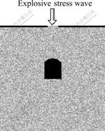
Fig.1 Model for calculation
The dynamic load in Fig.1 is explosive stress wave, which is on the ground and is above the tunnel. For simplification of calculation, stress wave is assumed as a pulse load in general dynamic analysis. Here, only influence of spherical explosive stress wave on tunnel failure is considered, and it is assumed that the shape of pulse stress wave loaded to tunnel is echelon, as shown in Fig.2, in which operating time is 1.5 μs, and operating peak value is 220 MPa.
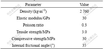
The mechanical parameters for surrounding rock are listed in Table 1.
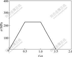
Fig.2 Loading pulse on ground and above tunnel
Table 1 Mechanical parameters for rock
In numerical simulation, the numerical sample model is used to represent the practical model. The numerical sample model is 100 mm×100 mm, and is composed of 200×200 elements with dimensions of 0.5 mm×0.5 mm. The material is assumed to be hetero- geneous, and the mechanical properties of these elements are assumed to conform to a given Weibull distribution, and the Weibull distribution parameters are listed in Table 2. The macro mechanical parameters of sample composed of elements listed in Table 2 correspond approximately to the rock mechanical parameters shown in Table 1.
It is assumed that surrounding rock of tunnel is reinforced. In order to analyze the influence of surrounding rock reinforcing on failure process of tunnel under explosive stress wave, two upright walls and arch of numerical sample tunnel shown in Fig.1 are reinforced. The thickness of reinforcing layer is that of 5 elements (2.5 mm). Interface between reinforcing mass and surrounding rock is ideal. The model after being reinforced is shown in Fig.3, and mechanical parameters of reinforcing mass elements are listed in Table 3.
Table 2 Weibull distribution parameters of rock material
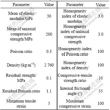
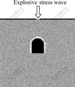
Fig.3 Model for numerical specimen of tunnel after wall and arch being reinforced
Table 3 Weibull distribution parameters of material for tunnel reinforcing
Four sides of numerical model are assumed as free ones, and only the propagation process before stress wave reaches the numeration boundary is considered. The model described above is simplified as plane strain problem to be solved. In numerical simulation, the step length of time is 0.1 μs.
3.2 Numerical simulation and analysis
3.2.1 Failure process of tunnel under explosive loading
In numerical specimen model as shown in Fig.1, spherical stress wave is loaded on the ground, and waveform of spherical stress wave is shown in Fig.2.
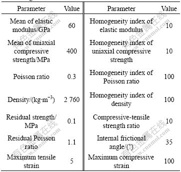
Due to the limitation of page, only the fracture processes for the shear stress field of the time steps are used, as shown in Fig.4. In the following figure of stress distributions, the gray degree denotes the corresponding magnitude of element shear stress, i.e. the brighter the point, the greater the shear stress of the element; and the black points indicate failure of elements. The bright half circularity in Fig.4 denotes the wavefront of the spherical surface explosive stress wave, which propagates from top of specimen to bottom. Seen from shear stress field, there is a black hole at the place of wave origination of the spherical explosive stress wave, denoting failure of elements here. Based on stress analysis, failure of elements here is caused by compression stress. The stress wave after the black hole is largely attenuated, and then there is few failure of elements in area where stress propagates, i.e. there is smaller area of black dot in shear stress (Fig.5). When stress wave propagates till about 90th loading step (loading time is 9 μs), the spherical explosive stress wave reaches the wall of tunnel roof, and reflection of stress wave occurs at the wall of tunnel, and then spallation fracture appears at the wall of tunnel due to tension stress, as shown in the maximal shear stress distribution figure at 110th loading step (loading time is 11 μs). With the reflection of stress wave at the wall of tunnel, the phenomenon of spallation failure of tunnel wall becomes more and more obvious. After stress wave propagates through tunnel, the tunnel stops to spall. Moreover, the diffracted wave may be seen when stress wave propagation passes through cave, as a result, there is a gap on the wavefront at the bottom of tunnel.
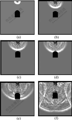
Fig.4 Maximal shear stress distribution of failure process of surrounding rock under spherical explosive stress wave: (a) 30th step; (b) 70th step; (c) 90th step; (d) 110th step; (e) 170th step; (f) 290th step
From forementioned analysis, the stress wave propagation phenomenon can be simulated realistically by using numerical code RFPA2D. Numerical analysis indicates that the failure of tunnel under explosive stress wave is mainly spallation caused by tensile stress. The conclusion is in agreement with that of WANG[14], i.e. the main failure pattern of tunnel under explosive loading is tensile spallation.
3.2.2 Influence of tunnel reinforcing on failure process of tunnel under explosive loading Numerical specimen model is shown in Fig.3, and loading pulse is shown in Fig.2. Except that the tunnel is reinforced, other condition is the same as the model shown in Fig.1 (thereinto shape and area of section of tunnel are unaltered).
The maximal shear stress distribution of the failure process of the surrounding rock of reinforced tunnel under explosive stress wave is shown in Fig.5. The behaviour of stress wave propagation in Fig.5 is almost the same as that in Fig.4. Seen from Fig.5, also, when stress wave propagates till about 90th loading step (loading time is 9 μs), the spherical explosive stress wave reaches the wall of tunnel roof, and reflection of stress wave occurs at the wall of tunnel, and then spallation fracture appears at the wall of tunnel due to tension stress. Contrasting shear stress distribution figures of 110th loading step in Fig.4 and Fig.5, it is found that the place at which spallation failure appears is different, i.e. the place at which spallation of unreinforced tunnel occurs is near the wall of tunnel roof, and the place at which spallation of reinforced tunnel occurs is at the interface of reinforcing mass and initial rock mass. Moreover, fracture propagates along interface,
Fig.5 Maximum shear stress distribution of failure process of reinforcing tunnel under explosive stress wave: (a) 30th step; (b) 70th step; (c) 90th step; (d) 110th step; (e) 170th step; (f) 290th step
as shown in shear stress distribution figures after 110th loading step in Fig.5. The gray degree of the maximal shear stress distribution figure of reinforcing rock mass of tunnel is brighter than that of other place of surrounding rock since 110th loading step, indicating that the stress of reinforcing rock mass of tunnel is greater than that of other surrounding rock, and spallation failure as shown in Fig.4 does not appear.
The result indicates that reinforcing of tunnel may transfer the place of spallation failure, and rockfall and collapse induced by spallation failure are restrained by reinforcing rock mass. So, stability of surrounding rock of tunnel is increased. The conclusion is in agreement with that of CAO[13], i.e. explosion resistance function of sprayed layer is to prevent from collapse of unstable rock and stop spallation of stable surrounding rock under strong explosive impact load.
In order to further analyze the influence of tunnel reinforcing on failure process of surrounding rock of tunnel, the relationship of major principal stress vs time, the minimal principal stress vs time, the maximal shear stress vs time, and vertical displacement vs time of center point of roof of unreinforced tunnel and reinforced tunnel are shown in Figs.6-9, respectively. Seen from Figs.6-8, the absolute values of peak value of major principal stress, the minimal principal stress and the maximal shear stress at center point of roof of reinforced tunnel are less than those of unreinforced tunnel. This is caused by stress wave reflection when stress wave propagates from surrounding rock mass to reinforcing rock mass, in which the mechanical parameters, such as that of elastic modulus and strength, are larger than those of initial rock of surrounding rock. Furthermore, the stress response at center point of roof at reinforced tunnel is all ahead of that of unreinforced tunnel because propagation velocity of stress wave in surrounding rock is slower, and propagation velocity of stress wave in reinforcing rock mass is faster. Seen from Fig.9, the response characteristics of vertical displacement of center point of roof of tunnel are that the displacement of roof of unreinforced tunnel linearly increases on the whole, and the displacement of roof of reinforced tunnel fluctuates with propagation of stress Wave. Moreover,
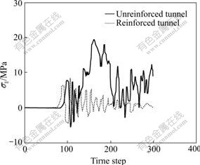
Fig.6 Curve of major principal stress σ1 vs time step at center point of tunnel roof
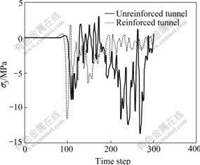
Fig.7 Curve of minimal principal stress σ3 vs time step at center point of tunnel roof
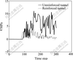
Fig.8 Curve of maximal shear stress τ vs time step at center point of tunnel roof
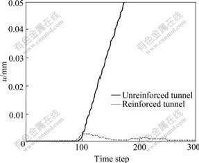
Fig.9 Curve of vertical displacement u vs time step at center point of tunnel roof
displacement of reinforced tunnel is quite smaller than that of reinforced tunnel. This indicates that tunnel reinforcing not only restrains the failure of tunnel wall, but also reduces the displacement of tunnel roof. Thus the stability of tunnel is increased.
In forepart design of reinforcing rock mass of tunnel under static loading or dynamic loading, reinforcing rock mass is divided from surrounding rock of tunnel, and the action of rock mass on reinforcing rock mass is replaced by certain load acting on reinforcing rock mass (sometimes counter stress of surrounding rock is considered based on Wenkel hypothesis), i.e. reinforcing rock mass of tunnel is regarded as ground structure to calculate according to the principle of structure mechanics. This kind of point of view is very obsolete[14]. In numerical simulation in this work, not only the inhomogeneity of rock but also the contact action between surrounding rock and reinforcing rock mass are considered. This is much more practical.
4 Conclusions
1) The stress wave propagation phenomenon can be simulated realistically by using numerical code RFPA2D (dynamic edition).
2) Spallation fracture appears at the wall of tunnel due to tension stress induced by reflection of stress wave, and the place at which spallation of unreinforced tunnel occurs is near the wall of tunnel roof, and the place at which spallation of reinforced tunnel occurs is at the interface of reinforcing rock mass and initial rock mass. Moreover, fracture propagates along interface, which shows that the place of failure of surrounding rock of tunnel is transferred because of tunnel reinforcing, and the rockfall and collapse caused by failure of surrounding rock of tunnel are restrained by tunnel reinforcing, consequently stability of tunnel increases.
3) The absolute values of peak value of major principal stress, the minimal principal stress and the maximal shear stress at center point of roof of reinforced tunnel are less than those of unreinforced tunnel. However, the stress response at center point of roof of reinforced tunnel is all ahead of that of unreinforced tunnel.
4) The response characteristics of vertical displacement of center point of roof of tunnel are that the displacement of roof of unreinforced tunnel increases linearly on the whole, and the displacement of roof of reinforced tunnel fluctuates with propagation of stress wave. Moreover, displacement of reinforced tunnel is quite smaller than that of unreinforced tunnel. It indicates that tunnel reinforcing not only restrains the failure of tunnel wall, but also reduces the displacement of tunnel roof, which result in the stability of tunnel increasing.
References
[1] CAI Mei-feng, XIAO Ying-bo. Law of deformation and failure of rocks surrounding reinforced tunnel in complicated rock mass [J]. Metal Mine, 2006(3): 29-31. (in Chinese)
[2] HOEK E, BROWN E T. Underground excavation in rock [M]. London: Institution of Mining and Metallurgy, 1980.
[3] JIANG Yao-dong, ZHAO Yi-xin, SONG Yan-qi, LIU Wen-gang, ZHU Dao-jian. Analysis of blasting tremor impact on tunnel stability in coal mining [J]. Chinese Journal of Rock Mechanics and Engineering, 2005, 24(17): 3131-3136. (in Chinese)
[4] LI Xi-bing, GU De-sheng. Rock impact dynamics [M]. Changsha: Central South University of Technology Press, 1994. (in Chinese)
[5] LI Xi-bing, ZUO Yu-jun, WANG Wei-hua, MA Chun-de, ZHOU Zi-long. Constitutive model of rock under static-dynamic coupling loading and experimental investigation [J]. Trans Nonferrous Met Soc China, 2006, 16(4): 714-722.
[6] XU Zeng-hui, SONG Hong-wei, ZHAO Jian. Numerical analysis of stability of tunnel surrounding rocks under earthquake [J]. Journal of China University of Mining and Technology, 2004, 33(1): 41-44. (in Chinese)
[7] ZHENG Ji-wang, CHEN Li-zhen. Stability analysis of surrounding rock of excavation under the blasting load [J]. Ground Pressure and Strata Control, 2004(4): 53-55. (in Chinese)
[8] TAO Lian-jin, ZHANG Zhuo-yuan, FU Xiao-min. Stability analysis of surrounding rock mass of underground excavation rock mass under seismic load [J]. Chinese Journal of Geological Hazard and Control, 1998, 9(1): 32-40. (in Chinese)
[9] XUE Ya-dong, ZHANG Shi-ping, KANG Tian-he. Numerical analysis of dynamic response of rock bolts in mining tunnels [J]. Chinese Journal of Rock Mechanics and Engineering, 2003, 22(11): 1903-1906. (in Chinese)
[10] LITWINISZYN J. A model for the initiation of coal-gas outbursts [J]. Int J Rock Mech Min Sci & Geomech Abstr, 1985, 20(1): 39-46.
[11] WU Xiang-yun, LI Huan-qiu, LI Yong-chi, YANG Ren-hua. Research on dynamic computation for shotcrete and rock bolt supporting and integral lining structures in rock mass [J]. Chinese Journal of Rock Mechanics and Engineering, 2005, 24(19): 3561-3565. (in Chinese)
[12] KIRZHNER F, ROSENHOUSE G. Numerical analysis of tunnel dynamic response to earth motions [J]. Tunneling and Underground Space Technology, 2000, 15(3): 249-258.
[13] SHENG Hong-guang, ZHANG Yong. Analysis on anchoring technology of tunnel rock mass under penetration explosion of projectiles [C]// Proceeding of Fifth Council and Ninth Annual Symposium of Protection Engineering Branch of China Civil Engineering Society. Changchun: Civil Engineering Society, 2004: 1542-1546. (in Chinese)
[14] WANG Cheng-shu. The failure modes of shot crete lining of tunnel under blast loading [J]. Chinese Journal of Rock Mechanics and Engineering, 1989, 8(8): 73-91. (in Chinese)
[15] TEDESCO J W, ROSS C A, MCGILL P B, O’NEIL B P. Numerical analysis of high strain rate concrete direct tension tests [J]. Comput Struct, 1991, 40(2): 313-27.
[16] ZHU W C, TANG C A. Numerical simulation of Brazilian disk rock failure under static and dynamic loading [J]. International Journal of Rock Mechanics and Mining Sciences, 2006, 43(2): 236-252.
Foundation item: Projects(50874020, 50504005 and 50490274) supported by the National Natural Science Foundation of China; Porject(2007CB209407) supported by Major State Basic Research Development Program of China; Project(2005038250) supported by Postdoctoral Science Foundation of China
Received date: 2008-03-28; Accepted date: 2008-05-25
Corresponding author: ZUO Yu-jun, PhD; Tel: +86-411-87403606; E-mail: zuo.yujun@yahoo.com.cn

