聚合材料管状微型元件成形设备和模具的开发
来源期刊:中国有色金属学报(英文版)2012年第z2期
论文作者:Jie ZHAO Arthur Lan Kuan YIP Yi QIN Akhtar RAZALI Zhi-cong FEI
文章页码:214 - 221
关键词:热压印;微成形;台式微制造系统;聚合材料管状微型元件
Key words:hot-embossing; micro-forming; desktop micro-manufacturing system; polymeric tubular micro-components
摘 要:介绍了有关台式热压印机系统及模具的开发,使其能实现聚合材料管状微型元件的批量生产,以满足不同的应用要求。开发的过程中考虑了多种因素的影响,如机器的动态性能、模具精度导轨、模具的加热和冷却、加工原料的送取自动化、控制策略等。开发的过程同样也参考了有限元分析及一系列实验的结果。提到的一体机系统现在已经加工组装完成,并进行了几个示范元件的成形测试,且取得了良好的结果。
Abstract: This paper reports the work associated with the development of a desktop hot-embossing machine system and tools which would enable volume production of polymeric tubular micro-components for various applications. The development was undertaken by considering factors such as machine dynamic performance, precision guides to tools, tool heating and cooling, raw material feeding and end-part collection, control strategy. It was assisted with FE analysis and a series of forming experiment. An integrated machine system has now been constructed and tested with the forming of several demonstration-components. A good result was obtained from these tests.
Trans. Nonferrous Met. Soc. China 22(2012) s214-s221
Jie ZHAO, Arthur Lan Kuan YIP, Yi QIN, Akhtar RAZALI, Zhi-cong FEI
Department of Design, Manufacture and Engineering Management, The University of Strathclyde, Glasgow, G1 1XJ, UK
Received 28 August 2012; accepted 25 October 2012
Abstract: This paper reports the work associated with the development of a desktop hot-embossing machine system and tools which would enable volume production of polymeric tubular micro-components for various applications. The development was undertaken by considering factors such as machine dynamic performance, precision guides to tools, tool heating and cooling, raw material feeding and end-part collection, control strategy. It was assisted with FE analysis and a series of forming experiment. An integrated machine system has now been constructed and tested with the forming of several demonstration-components. A good result was obtained from these tests.
Key words: hot-embossing; micro-forming; desktop micro-manufacturing system; polymeric tubular micro-components
1 Introduction
Needs for tubular micro-components such as that used for medical-devices, heating management systems, and micro-fluidic-devices in general, have been increased significantly in the past decades. Efforts in micro-manufacturing have, however, been focused largely on the conversion of other types of components among which most are in bulk- and sheet-forms or surface-oriented fabrications [1]. Manufacturing microsystem development [2-5] and manufacture of metal tubular micro-components were addressed in the EU FP6 MASMICRO project [6] for which a unique machine system was developed based on a hydroforming configuration [7]. Manufacture of polymeric tubular micro-components was not addressed in this project while those components have found significant application potentials in newly designed medical instruments and micro heat-management systems.
A micro-tube without too many variations along its length may be produced with a micro-extrusion process. With such a process, it is, however, difficult to achieve complex geometry-forms varying along its length. Micro-injection-moulding is a popular choice for the manufacture of polymeric micro-components [8], but it would not be ideal for the shaping of long tubular components. Another issue relates to a long process chain to be used. In the medical sector, manual and semi-automated devices have been used to enable tipping, necking, flaring and expansion. These are, however, not suitable for a production purpose, even without mentioning the issues relating to the shaping of micro-tubes (e.g. diameter<1.0 mm).
For the conversion of polymeric micro-tubes as starting materials into functional tubular micro- components, a more efficient shaping process is required to convert a basic extruded polymeric tube into a more complex component-form. This effect would add values and increase functionality of micro-tubes, which is being addressed in the EU FP7 POLYTUBES project [9]. A typical example is the use of polymeric tubular component as a filter in a medical instrument for an electrophysiology study (Fig. 1). Such a component has shaped features at the tips and at intermediate sections, and requires a gradually reduced inner channel with the smallest pore size of 2-5 μm.
Considering small diameters of the micro-tubes to be dealt with, hot-embossing was qualified as an alternative process for the shaping of polymeric micro-tubes [10]. Merits of the process are also due to the mass production capability and its low-cost manufacturing nature. Hot-embossing is an established process which can be used for the manufacture of micro-structures on surfaces of the substrate materials including polymer, glass and metals. It has a capability to fabricate structures with high aspect ratios with part features at the micro- and nano-size ranges [11]. Nevertheless, forming of tubular micro-components through hot-embossing was not attempted previously.
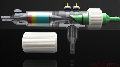
Fig. 1 A medical instrument using tubular micro-components
Adoption of a hot-embossing technology for the manufacture of tubular micro-components is a novel solution to meet various demands for applications while maintaining a volume production capability and low manufacturing cost [12,13]. Several development needs were to be met in order to develop a reliable hot-embossing process and corresponding machine system [14]. In this paper, the development of a desktop hot-embossing machine system and tooling is reported. It covers considerations for the machine design, machine frame analysis, tool design, handling design and control strategy, followed by machine construction and validation trials on several polymeric materials. Conclusions will then be drawn on the process feasibility and machine-system performance.
2 Micro-tube hot-embossing process
With some variations from the conversional hot-embossing process [15], shaping of micro-tubes with hot-embossing is affected by the following steps (Fig. 2): 1) the tool-sets are heated up to the required temperature by cartridge heaters. 2) The tube is then fed into the lower-shaping die. 3) The tube is heated up rapidly by the die due to the small volume of the material involved. 4) The lower-die contains the tube and a gripper holds the tube while it is pressed by the upper-die. A pre-set pressure is maintained for a certain time to allow for shape-setting and fusion-bonding at the inner folded-interfaces, and hence, an inner channel/pore can be formed. To achieve a shape stability, water cooling is taken into account as an option in design of the tools. 5) The upper die-set is then lifted whilst a mechanical gripper still holds the shaped tube. 6) The flash formed may be trimmed off by a shearing process (similar to that in progressive stamping). And 7) the scraps and shaped part are removed from the lower-die.
By comparing with other micro-tube forming processes, merits of hot-embossing of micro-tubes include: direct shaping of 3D features from the tubes, a high production-rate possible, easy process control, allowing for a quick change of tooling, less complexity of the machine motions and construction, and being easy for production automation realization, etc.
3 Considerations for machine development
The requirements for the development of the machine system and tools were mainly in four categories:1) to meet a requirement for the development of an integrated manufacturing platform which is to integrate several desktop machines on a single platform to form a process chain for the shaping of polymeric micro-tubes as the project’s ultimate goal of the EU POLYTUBES project; 2) to be able to shape the micro-tubes with outer diameters of 1.0-2.0 mm and with various thicknesses, from the thin walled tubes to thick-walled tubes, and the length of a tube is up to 50 mm. A critical part is to control the inner-pore size and accuracy to be achieved (e.g. 1.0-2.0 μm); 3) to achieve a low-cost volume production capability; and 4) to be able to use the machine for other applications such as hot-embossing of glass or thin foils.
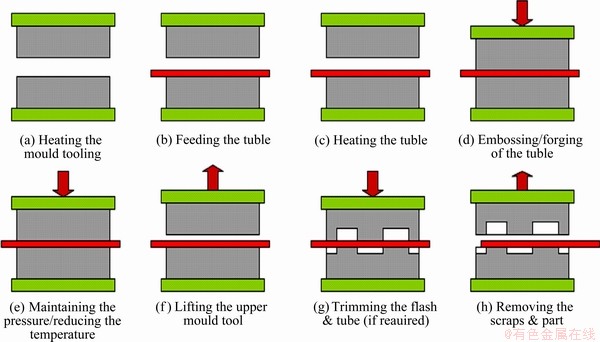
Fig. 2 Process of hot-embossing of micro-tube
One of the main constraints to the development of miniature desktop industry micro-manufacturing machine is the supply of standard machine-elements/ parts for constructing the machine, which will still be the case for some time, especially for the development of some special purpose miniature-machines, until the designs of these machines are fully standardized and industrially acceptable. Scaling down from the large- scale hot-embossing machine designs to the miniature ones would not be straightforward due to the above consideration as well as size-effect relating to the die/mould design and fabrication, handling of the raw material and formed part, control of the workpiece/tool interfaces, etc.
To have a production capability also means compromising between the machine sizes and production-related operation environment such as accommodating a handling system and even a continuous material-feeding system. This means that although the force required for shaping a single polymeric micro-tube would probably be quite low (e.g. tens of Newton) for some materials, the machine design should not just take this one factor into account. Another consideration is for other applications of the machine system in the future. To integrate the machine into a manufacturing platform also means needing to consider physical interfaces to other machines and the global handling-system.
To enable high-quality shaping of polymeric micro-tubes to form inner channels with required geometries, the machine system should be of such features as easy setting of the force, holding time, stroke, heating/cooling through an easily programmable system. It has been approved that those are the key parameters for achieving high-quality parts, especially in controlling the shapes and dimensions of the central pores of the tubular components to be formed [10]. Other issues relate to the tool-quality and precise positioning of the micro-tube inside the dies, etc.
4 Machine system development
4.1 Machine frame
Various machine concepts were examined with regards to the frame design, automation and general design features. From the findings of the research activities, a range of machine concept layouts with the embodiment of different machine technologies were generated (Fig. 3). The evaluation of the various machine layout concepts were carried out by an in-depth review against the required hot-embossing machine specifications and thus eliminating weak concepts from the further development.
The final selected machine layout was designed as a four-column construction to provide a high stiffness frame in order to minimize possible frame deflections. This physical layout design would also offer increased flexibility with material handling options to allow material transport in various directions for other applications. An analysis of the machine frame was carried out using the FEM (Fig. 4) and the objective was to predict the possible deflection of the frame during hot-embossing. It was also to find out if there will be significant transverse loads acting on the linear bushing. The FE study showed that the machine frame designed is valid for the required performance in terms of the stiffness and level of the stresses.
4.2 Tool development
The tool-system consists of an upper die and a lower die with die-inserts (Fig. 5). The forming die-sets with complex structural features were made with micro-milling, die-sinking and wire EDM. Each die is attached to the die holding-components, the design of which allows for quick replacement of the die-inserts.
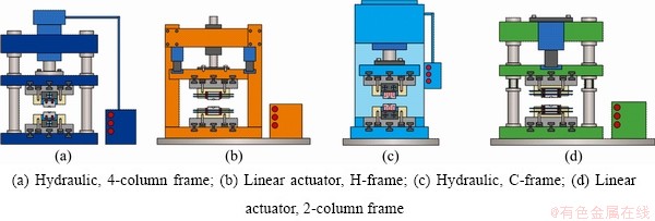
Fig. 3 Possible machine layouts
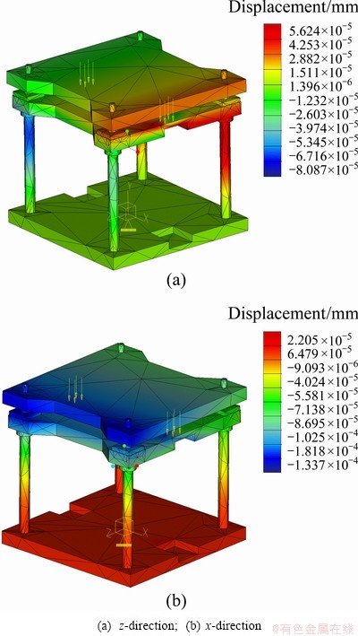
Fig. 4 FE analysis of machine frame
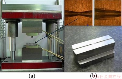
Fig. 5 Die-sets (a) and a die-insert (b)
Use of tool plates also allows for connection of the die-sets to the machine frame with standard screw fasteners. The electrical cartridge heaters were selected to enable the required heating for hot embossing. Water cooling was used as an option for the cooling system. The hot-embossing tool-system design was finalized after several iterations of design and forming experiment, including testing on a manual test-rig for hot-embossing of micro-tubes. The current tool-system is of the following features: modular insertion of the core dies; precision guiding of the micro-tube inside the dies; heating and cooling units with a temperature control system; heat-insulation for an improved heating- efficiency; precise alignment of the upper and lower die-sets through two additional guide pillars, etc.
4.3 Tube-handling
To ensure an fully autonomous operation, a micro-tube handling system (Fig. 6) was designed and the design integrated to the hot-embossing machine design. This handling system was designed to feed the raw material (micro-tube) and hold it during embossing. After the embossing, the shaped tube is removed from the die and transferred to a buffer zone or delivered to a robotic arm if post processing is required. Due to the compact size of the machine, the handling system is required to be small, flexible, reliable, and easy to be assembled and disassembled. The standard mounting components cannot meet all of those needs. Therefore, a multi-degree of freedom handling system was developed as an integrated part of the hot-embossing machine system, which is able to move easily in any position in x-y-z axes to ensure that the machine can be easily integrated into the manufacturing platform being developed. To realize this motion, three pneumatic linear actuators and one rotary actuator were used. One top of that, a micro-gripper with an extended clamp was used to pick-up/drop-off the micro-tube/component and also firmly hold the tube during embossing. The control of this handling system is described in the section concerning the control system.
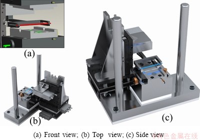
Fig. 6 3D model of handling-system
4.4 Press
Following the development of the hot-embossing tools and the tube-handling system, the press and integration of the systems were developed subsequently. The press force was achieved with an electrical linear actuation technology to provide a stable and controlled linear force as required for the hot-embossing process. An electrical linear actuator which can be controlled in force, velocity, stroke and holding time was considered to be appropriate for the machine development. The upper and lower machine frame plates are fixed with outer machine-guide posts as a part of the four-column frame construction (Fig. 4). The displacement of the upper die-set is facilitated by the middle frame-plate which is driven by the press ram. The press is equipped with one unit of the rotary linear actuators which was specifically designed for press applications. The actuator has a push-pull force of up to 3 kN. At a no load mode, the actuation speed could reach up to 120 mm/s. The actuator came with embedded high-resolution 11bit rotary encoder which acts as a positional feedback system. This ensures a flexibility in terms of changes of the ram position as well as coping with any future die-designs. Due to the physical space-constraint imposed on the machine system, a linear actuator with a 100 mm press stroke was selected. It moves vertically under the guidance of the lubricated ball-bushing guide elements which ensures the alignment of the press and the tooling.
4.5 Control system
The linear press is also equipped with a built-in load sensor, and it is used to measure the machine ram force. With this force-based monitoring, the actuator can be controlled by setting a designated press-force, therefore, it is well suitable for hot-embossing where a constant holding force is often required during the part/feature shape setting. To form accurate inner pores in micron sizes (relatively small geometry) from the micro-tubes (relatively large geometry), it is crucial to form good joints between the folded material-surfaces through the polymer’s fusion at the contact interfaces under the heating. This process would need to maintain the forming pressure for a period of time. To provide the pre-set machine force and holding time is, therefore, important for the machine system developed.
Each cartridge heater which is embedded into the die-set is controlled by a PLC-controller and it allows for presetting of the heating temperature. Once the desired temperature is set, the controller monitors the temperature in the die so that the rise or fall in temperature is corrected accordingly.
Two pneumatic stages used for the tube-handling system are controlled through connecting each stage’s solenoid valve to the press actuator’s servo drive. On top of that, a rotary actuator is used to realize an additional axis for the rotary motion. The handling system also uses a solenoid actuated gripper to hold the micro-tube. A low-force solenoid was chosen for handling in order to avoid excessive force possibly applied onto the fragile tube. The handling system is controlled with the servo controller which is used also to control the press actuation-system. The servo-drive controller used in this machine has a capability of controlling 8 axes of motion simultaneously. The servo-drive is also equipped with multiple input/output terminals which provide convenience for the integration of an emergency stop and other safety management measures into the machine system. The servo drive uses low energy electricity as it is only needed for producing low current supply for the actuation and the handling system. Figure 7 shows a schematic to show a connection of the main machine- elements/subsystems for control.
4.6 Machine realization
Figure 8 shows a computer model of the designed desktop machine-system for hot-embossing of micro- tubes. The prototype machine-system was built with integration of the elements/subsystems described above.
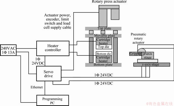
Fig. 7 Schematic of machine system connection
The system has following features: integrated force, position and signal control; the maximum force of 3 kN; the smallest force measured of 0.83 N; the maximum stroke of 100 mm; distance resolution of 0.049 μm; working temperature up to 500 °C; 4-axis micro-tube handling unit; and a control interface with selections via PC.

Fig. 8 Model of machine system
5 Machine system validation
The machine system was tested by forming the demonstration parts for a variety of polymeric micro-tubes (different materials and dimensions). For each batch of the tubes (same type of the material and same dimensions), the machine was tried at different heating temperatures, periods of the holding time and levels of the forming-pressure, in order to try on the machine control as well as to optimize the hot-embossing process. The heating process as well as heat transfer within the die/machine structural parts as also checked on heating efficiency and isolation to the main machine-frame. The handling system was modified several times for a better integration into the machine. The design of some of its structural parts was modified for achieving better positional accuracy of the tube gripper and its stiffness. The formed polymeric tubular parts with micro-features are inspected with the following methods: visual inspection for the general forming-quality; water-sealing test on the formation of the central pores; optical inspection on the shaped profiles; dimensional measurement on shaped flashes; and observation of the sectioned pores under a SEM machine. Figure 9 shows one of the working status of the machine and two samples of the formed parts.
The machine system was also tested for a possible, continuous hot-embossing process by integrating an in-house developed high-precision feeder into the machine. The feeder was originally developed for high-speed micro-sheet-metal-forming [6]. With continuous feeding of a micro-tube coil, shaping of the tube at a constant interval along the coil length is possible, which renders a potential for a high volume production of the shaped polymeric tubular micro- components.
6 Results and discussion
Polymeric tubes of different material types and thicknesses were obtained from commercial suppliers [16-18] and project partner, which were shaped successfully (Table 1). Very good material flow on each formed tube was observed (Figs. 9 and 10), especially when the dies were heated up to the required temperature. The material handling system was also proved to work well and well synchronized with the press machine. The results from the validation trials showed that the machine meets the design specifications.
Table 1 Hot-embossing formability of polymeric micro-tubes
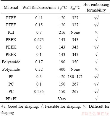
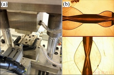
Fig. 9 Close view of working status of machine (a) and samples of formed parts (b)
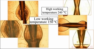
Fig. 10 Specimens produced at two different temperatures
For the micro-tubes tested, the formability of these materials for hot-embossing is highlighted in Table 1. Although most of the thermoplastic materials are suitable for the hot-embossing process introduced, the preference for easy process control and for achieving good quality parts is:
1) Amorphous materials since these have a larger moulding range.
2) Being in a certain range of elasticity―the material is not too brittle or too elastic.
3) Thick-walled tubes for achieving the required, various inner-pore shapes and sizes through controlling volume-material flows during embossing. The instability of thin-walled tubes needs to be overcome in the beginning of the shaping process while only limited material flows could be utilized to achieve certain shaped features including pore-geometries.
4) A proper material-selection which well considers the applications of a material. The hot-embossing process may result in the change/altering of the material properties due to the elevated temperature. This issue may need to be taken into account seriously when selecting a micro-tube for a particular application such as that for a medical instrument. Possible harmful smells generated during hot-embossing of some polymeric materials also need a special care, from the health and working-environment point of view.
Influences of the working temperature on the hot-embossing process are significant. Figure 10 shows a comparison of the shaped tubes with two different temperatures of 150 °C and 240 °C for PTFE tubes respectively. With a higher temperature, the shaped sections are clearly seen with even material flows and the inner-bore-reduced section (necking) was sealed properly with no water leak found during a water-sealing test.
For some amorphous materials, easy shaping suggests that only a very short forming cycle (especially, short holding time) is needed while rapid cooling of the small volume material (micro-size tubes) also indicates that cooling down of the die-set during hot-embossing is not necessary. The latter also suggests that a very short forming cycle can be deployed for the hot-embossing of those materials, therefore, a high production-rate can be achieved.
7 Conclusions
A hot-embossing machine system has been developed for the shaping of polymeric micro-tubes for various applications. The system has been assessed on its produceablity, reliability, repeatability, and degree of automation. The various materials have been tested and the samples examined with optical-measurements and SEM in detail. The machine developed has been proven to be efficient for producing functional, tubular micro- components from amorphous and semi-crystalline polymeric micro-tubes. The shapes/features can be formed at the tips and/or at intermediate sections, and the sections of inner pores/channels below 5 μm in width/height have been observed via SEM. A production rate exceeding 20 parts per minute is achievable with a continuous tube-feeding strategy. The machine system/ tools will be refined further for: a better strategy for processing parameter control in order to achieve more accurate part-geometries/features with a good repeatability; a better solution for guiding the tube during hot-embossing; implementation of high-efficiency cooling for the die-sets; and establishment of detailed, optimal process-widows for the polymeric tubular materials tested. Further developments will also include extension of the applications to the shaping of other component-forms and materials.
Acknowledgments
Support from the European Commission for conducting research into the “A Process Chain and Equipment for Volume Production of Polymeric Micro-Tubular Components for Medical Device Applications (POLYTUBES)” (NMP2-SE-2009-229266) is acknowledged. Collaboration with all project partners in developing the hot-embossing process and the machine are particular acknowledged.
References
[1] QIN Y. Micro-manufacturing engineering and technology [M]. Oxford: Elsevier, 2010.
[2] QINY, BROCKETT A, MA Y, RAZALI A, ZHAO J, HARRISON C, PAN W, DAI X, LOZIAK D. Micro-manufacturing: Research, technology outcomes and development issues [J]. Int J Adv Manufact Technol, 2010, 47: 821-837.
[3] QIN Y. Micro-forming and miniature manufacturing systems―Development needs and perspectives [J]. Journal of Materials Processing Technology, 2006, 177(1-3): 8-18.
[4] QIN Y, MA Y, HARRISON C, BROCKETT A, ZHOU M, ZHAO J. Development of a new machine system for the forming of micro-sheet-products [J]. International Journal of Material Forming, 2008, 1(1): 475-478.
[5] HECKELE M, BACHER W, MUELLER K D. Hot embossing―the moulding technique for plastic microstructures [J]. Microsystem Technologies, 1998, 4(3): 122 -124.
[6] EU FP6 MASMICRO project [2012-04-10]. http://www.masmicro. eu/.
[7] HARTL C. Micro-hydro-forming [C]//QIN Y. Micromanufacturing Engineering and Technology. Oxford: Elsevier, 2010: 146.
[8] EU FP7 POLYTUBES project [2012-04-10]. http://www.polytubes. net/polytubesv1/.
[9] TOSELLO G, HANSEN H. Micro-injection moudling [M]. QIN Y. Micromanufacturing engineering and Technology. Oxford: Elsevier, 2010: 90.
[10] ZHAO J, QIN Y, RAZALI A, YIP A L K, FEI Z. Hot-embossing of polymeric micro-tubes [C]//Proc 7th Int Conf on Micro Manufacturing. Evanston, IL, USA, 2012: 534-541.
[11] WORULL M. Hot-embossing [C]//QIN Y. Micromanufacturing Engineering and Technology. Oxford: Elsevier, 2010: 68.
[12] BECKER H, HEIM U. Hot embossing as a method for the fabrication of polymer high aspect ratio structures [J]. Sensors and Actuators, 2000, 83:130-135.
[13] HECKELE M, SCHOMBURG W K. Review on micro molding of thermoplastic polymers [J]. Journal of Micromechanics and Microengineering: Structures, Devices, and Systems, 2004, 14: R1-R14.
[14] EU Polytubes Consortium [R]. Technical Reports to the European Commission, 2011.
[15] WORULL M. Hot embossing: Theory and technology of microreplication [M]. William Andrews Publishing, 2009.
[16] RAZALI A, QIN Y, ZHAO J, HARRISON C, SMITH R A. Newly developed high-precision feeder for micro-sheet-forming [J]. Journal of Manufacturing Science and Engineering, 2011, 133(6): 061025-1-7.
[17] Goodfellow [2012-04-12]. http://www.goodfellow.com/, accessed in 2012.
[18] ProfessionalPlastics [2012-04-12]. http://www.professionalplastics.com/, accessed in 2012.
Jie ZHAO, Arthur Lan Kuan YIP, Yi QIN, Akhtar RAZALI, Zhi-cong FEI
Department of Design, Manufacture and Engineering Management, The University of Strathclyde, Glasgow, G1 1XJ, UK
摘 要:介绍了有关台式热压印机系统及模具的开发,使其能实现聚合材料管状微型元件的批量生产,以满足不同的应用要求。开发的过程中考虑了多种因素的影响,如机器的动态性能、模具精度导轨、模具的加热和冷却、加工原料的送取自动化、控制策略等。开发的过程同样也参考了有限元分析及一系列实验的结果。提到的一体机系统现在已经加工组装完成,并进行了几个示范元件的成形测试,且取得了良好的结果。
关键词:热压印;微成形;台式微制造系统;聚合材料管状微型元件
(Edited by YANG Hua)
Corresponding author: QIN Yi; E-mail: qin.yi@strath.ac.uk; ZHAO Jie; E-mail: j.zhao@strath.ac.uk
DOI: 10.1016/S1003-6326(12)61711-7

