J. Cent. South Univ. (2017) 24: 2164-2171
DOI: https://doi.org/10.1007/s11771-017-3625-3

Calculation of foundation pit deformation caused by deep excavation considering influence of loading and unloading
HUANG Ming(����)1, 2, LIU Xing-rong(������)2, ZHANG Nai-yang(������)1, SHEN Qi-wei(�����)3
1. College of Civil Engineering, Fuzhou University, Fuzhou 350108, China;
2. College of Civil Engineering, Chongqing University, Chongqing 400045, China;
3. China Railway 18 Bureau Group Co., Ltd., Tianjin 300222, China
 Central South University Press and Springer-Verlag GmbH Germany 2017
Abstract: A new analytical solution for ground surface settlement induced by deep excavation is proposed based on the elastic half space Melan��s solution, and the analytical model is related to the physical and mechanical properties of soil with the loading and unloading action during excavation process. The change law of earth pressure of the normal consolidation soil after the foundation pit excavation was analyzed, and elastic displacement calculation methods of analytic solution were further established given the influence of excavation and unloading. According to the change of stress state in the excavation process of foundation pit, the planar mechanical analysis model of the foundation excavation problem was established. By combining this model with the physical equations and geometric equations of plane strain problem with consideration of the loading and unloading modulus of soil, constitutive equation of the plane strain problem was also established. The loading and unloading modulus formula was obtained by using the parameter calculation method in Duncan-Chang curve model. The constitutive equation obtained from the model was used to calculate the soil stress state of each point to determine its loading and unloading modulus. Finally, the foundation pit displacement change after excavation was calculated, and thus the soil pressure distribution after retaining structure deformation. The theoretical results calculated by making corresponding programs were applied to engineering practice. By comparing the conventional calculation results with monitoring results, the practicability and feasibility of the calculation model were verified, which should provide a theoretical basis for similar projects.
Key words: foundation pit; Melan��s solution; loading and unloading; stress state; Duncan-Chang curve model
1 Introduction
The excavation of a foundation pit is the process of loading and unloading of soil inside and outside the foundation pit. The essential issue in this process is the unloading of soil which results in redistribution of formation stress and thus a wide range of changes in physical and mechanical properties of foundation pit soil. Among the most obvious is the change of soil modulus. LADD et al [1] used the concept of over-consolidated soils to deduce the undrained shear strength calculation formula for normal pressure of clay after the excavation unloading. LIU et al [2] obtained the formula of the unloading modulus through experimental research and theoretical derivation, and pointed out the significant difference between the unloading modulus of soft soil and the elasticity modulus or compression modulus obtained from conventional triaxial test, which was mainly shown from the modulus increase after unloading and the great influence of stress path on it. In this regard, a large number of scholars have made intensive studies [3-5]. In addition, HSIEH et al [6] carried out three types of tests to obtain the undrained shear strength of clay in excavations. ZHOU et al [7] conducted indoor experimental research on mechanical properties of soft soil under lateral unloading conditions, and the results showed there were some differences between the mechanical properties resulting from lateral unloading and those from axial loading under the same consolidation condition; MESRI et al [8] analyzed the relationship between undrained shear strength and consolidation pressure in the compression and extension shear modes, which indicates that the extension shear modes friction angle is larger for the compression shear modes.
As is known to all, the excavation process of foundation pit is always related to the supporting structure. Deformation of the supporting structure and that of the soil inside and outside the foundation pit are in dynamic change. Two factors are correlated [9-11] and critical in calculating the force on and deformation of the supporting structure and soil. Due to the interactions between supporting structure deformation and soil deformation, the soil pressure on the supporting structure is between static earth pressure and limit earth pressure, depending on the displacement of the supporting structure. In the traditional method of earth pressure calculation, however, only simple corrections are made to the limit earth pressure on the supporting structure. This also brings certain errors to the calculation. Concerning this issue, a model experiment was conducted, showing that the distribution of passive earth pressure on rigid retaining wall varies with the displacement mode. FANG et al [12] and CHEN [13] employed the coulomb��s limit equilibrium theory for the active earth pressure calculation of retaining wall considering translational wall movement. It is considered that the earth pressure against the back of the wall is due to the thrust exerted by a wedge of soil between the wall and a plane passing through the heel of the wall; WEI et al [14] put forward an analysis model of earth pressure related to displacement based on the Mindlin��s solution and analyzed the influence factors by using the difference between different limit earth pressures and static earth pressures.
In the current calculation of deformation during foundation pit excavation, empirical estimation method and numerical simulation method are most commonly adopted, compared to the less commonly used theoretical calculation [15]. During the excavation, both excavation unloading and supporting structure deformation should be taken into consideration. The former leads to change of soil modulus, while the latter plays a part in keeping the soil in a passive loading state. In this context, the foundation pit was divided into several zones for excavation in this work. A mechanical analysis model was established through theoretical analysis and an elasticity calculation model of soil deformation due to loading and unloading during excavation was provided. Meanwhile, by applying the theoretical results obtained in this work to engineering practice through corresponding programs, and comparing them with measured results, the feasibility and practicability of the theory was verified.
2 Constitutive model given influence of loading and unloading of foundation pit
During foundation pit excavation, soil below the excavation surface is subject to obvious vertical unloading, leading inevitably to rebound deformation of soil at the bottom of the pit. With the increase of excavation depth, the difference in heights between the soil inside and outside the pit grows larger. The resulting loading effect, along with overload effects of the surface, will drive movement of soil outside the pit and the supporting structure inwards to the pit, resulting in settlement of surface soil outside the pit and upheaval of soil in it. In the meantime, due to deformation of the supporting structure, soil within a certain area around the pit is under extrusion load. Therefore, during the excavation of foundation pit, deformation modulus of soil varies nonlinearly with the change of time and space [16]. In previous studies, scholars focused on lateral unloading over the range of the supporting structure��s height outside the pit and vertical rebound below the excavation face, while neglecting the influence of loading action during excavation on soil deformation, which to some extent led to calculation errors.
Figure 1 shows the stress path of strain on the excavation surface. On one hand, with the going on of the excavation process, deformation of the supporting structure inward to the pit occurs, followed by movement of soil outside and change of stress state. The stress path is AC, as shown in Fig. 1. On the other hand, due to the removal of upper soil, rebound deformation of soil below the excavation surface is found, and unloading or loading response under the action of the supporting structure is generated. The stress path is AMF, as shown in Fig. 1.
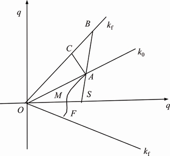
Fig. 1 Stress path
2.1 Loading and unloading moduli
Figure 2 shows the loading and unloading curves of (��1-��3)-��a in the plane strain problem. In the loading process, the principal stress difference (��1-��3) increases, i.e., ��(��1-��3)>0. At this time, the tangent modulus decreases, as manifested by the loading modulus  ; in the unloading process, principal stress difference (��1-��3) decreases, i.e., ��(��1-��3)<0. At this time, the tangent modulus increases, as manifested by the unloading modulus
  as a result, the state (either loading or unloading) of a point in the plane can be determined by the sign (either positive or negative) of ��(��1-��3). Through analysis, the loading and unloading moduli can be expressed as follows:
 (1)
(1)
where H(��) is the Heaviside function.
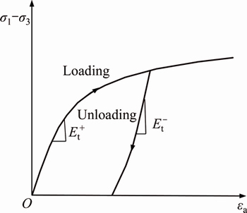
Fig. 2 Stress-strain curves of loading and unloading
In this work, the calculation method of the parameters in Duncan-Chang model curve is used to obtain the modulus formula [17], which is
 (2)
(2)
where Rf is the parameter of Duncan-Chang curve model and can be obtained through conventional triaxial test; ��1 and ��3 are the major principal stress and minor principal stress respectively during the excavation, and can be obtained from the stress calculation below; c and �� are strength indexes. Pa is the atmospheric pressure, and k, n and kur are experimental constants (kur=(1.2-3.0)k).
Moreover, in the excavation process, the density and volume of soil change accordingly, leading to further change in Poisson ratio of soil under the condition of natural foundation. On this account, the simple formula [17] is used as the Poisson ratio for calculation in this work:
 (3)
(3)
where vi is the initial tangent Poisson ratio, vtf is the tangent Poisson ratio at failure, and S is the stress level.
2.2 Constitutive model
By viewing the excavation of foundation pit as a plane strain problem, the constitutive model can be expressed as
 (4)
(4)
where elastic constants E and v are obtained from Eq. (1) and Eq. (3).
3 Analysis of foundation pit deformation given influence of loading and unloading
3.1 Simulation of stress state during foundation pit excavation
As shown in Fig. 3, the stress process of foundation pit excavation is comprised of three stages, which are the initial equilibrium stage before excavation (Fig. 3(a)), the instantaneous disequilibrium stage after excavation (Fig. 3(b)) and the stable stage after deformation (Fig. 3(c)). Before excavation, the supporting structure, under two equal and opposite static earth pressures generated by the self-weight of soil, is in the initial equilibrium stage, as shown in Fig. 3(a). At the moment when the excavation is completed and the soil is not yet deformed,the supporting structure, due to unloading of soil inside the pit, is under static earth pressure ��0 from soil outside the pit and static earth pressure  from soil at the bottom of the pit, and is thus in the disequilibrium stage, as shown in Fig. 3(b). After that, simultaneous occurrence of horizontal tilting is detected in soil inside the foundation pit and in supporting structure, and settlement deformation of surface around the foundation pit is also found. At this time, the earth pressure on the supporting structure changes from static earth pressure to one that is related to horizontal displacement, which brings the foundation pit to the equilibrium stage in the end, as shown in Fig. 3(c).
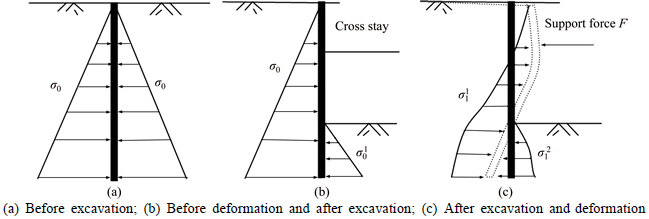
Fig. 3 Simulation of stress state:
3.2 Calculation model of soil outside foundation pit after excavation
For the soil outside the foundation pit and the supporting structure as a whole, as shown in Fig. 4, at the moment immediately after the excavation, the stress state of the whole structure consists of two elements, i.e., static earth pressure ��0 from soil outside the pit and static earth pressure from soil at the bottom of the pit.
Before excavation, the soil is in a semi-infinite space state; after excavation, it changes to a non-semi- infinite space state. For ease of later calculations, a virtual linear load P  or
or  is added to the supporting structure, as shown in Fig. 5, so that the state of soil in Fig. 4 is changed to semi-infinite space. Then the deformation mechanical model of soil outside the foundation pit is established.
Through model analysis in Fig. 5, ground settlement of soil outside the foundation pit and lateral deformation of the supporting structure can be determined by the following equations, respectively:
 (5)
(5)
 (6)
(6)
where  and
and  are the vertical displacement and horizontal displacement under the action of virtual load P1 respectively;
  and
and  are the vertical displacement and horizontal displacement under the action of virtual load P2 respectively;
  and
and  are the vertical displacement and horizontal displacement respectively under the action of cross stay 2F, which can be obtained with Melan��s solution.
3.3 Calculation model of earth inside foundation pit after excavation
After excavation and before deformation, static earth pressure against the supporting structure is generated by self-weight of the soil at the bottom of the foundation pit. Under the combined effect of acting force and reacting force, an equal and opposite force is generated by the supporting structure against the bottom of the pit, as shown in Fig. 6.
As can be seen from the figure above, the soil and stress at the bottom are distributed symmetrically. Therefore, half of the soil is used for analysis, where the model is a non-semi-infinite space. In order to convert it to a semi-infinite space, anti-symmetric mapping is adopted to obtain the deformation calculation model of soil at the bottom, as shown in Fig. 7.
By analyzing Figs. 6 and 7, the upheaval of soil at the bottom can be expressed as
 (7)
(7)
where  is the vertical displacement of soil on the left under the action of load P2 from the left;
  is the vertical displacement of soil on the left under the action of load P2 from the right; and
  is the settlement under the effect of gravity.
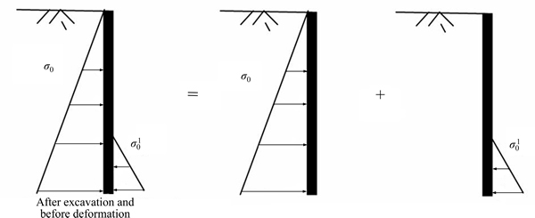
Fig. 4 Stress state of soil around foundation
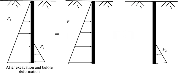
Fig. 5 Deformation calculation model of soil around foundation
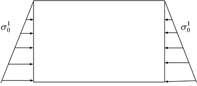
Fig. 6 Stress state of soil in excavation face
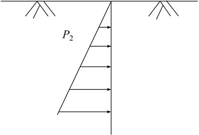
Fig. 7 Deformation calculation model of soil at bottom
3.4 Calculation of stress and deformation of earth
Assuming the materials have the same modulus, based on the Melan��s solution [18], a horizontal linear load is applied in the elastic semi-infinite space to calculate the stress of each point as follows:

 (8)
(8)

 (9)
(9)


 (10)
(10)
where ��x and ��z are the horizontal stress and vertical stress respectively, ��zx the shear stress in the plane, v the Poisson ratio of soil and q the horizontal linear load. Other parameters are shown in Fig. 8. Based on ��x, ��y, ��zx, and related geometry knowledge, principal stresses of soil ��1 and ��2 are calculated; based on plane strain calculation, minor principal stress ��3 is obtained as follows, ��3=��y=v(��x+��z).
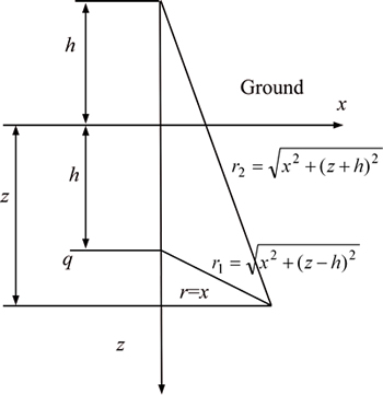
Fig. 8 Melan��s solution (linear load)
Within the elastic semi-infinite space, the uniformly distributed strip load with a load width of ��h=h2-h1 has a stress solution that is the integral of Melan��s solution within the range of h2-h1:


 (11)
(11)


 (12)
(12)

 (13)
(13)
For the isotropic plane strain problem, the physical and geometric equations respectively are
 (14)
(14)
 (15)
(15)
where Es is the elastic modulus of material and v the Poisson ratio, both of which are elastic constants considering the loading and unloading moduli of material, and are determined by Eqs. (1) and (3).
With Eqs. (14) and (15), the displacements in horizontal and vertical directions respectively are determined as follows:
 (16)
(16)
 (17)
(17)
By putting the equations together, the indefinite integral is obtained:


 (18)
(18)


 (19)
(19)
3.5 Calculation of earth pressure related to displacement
The change of supporting structure displacement leads to change of earth pressure, as can be seen from the variation of earth pressure with the displacement of supporting structure shown in Fig. 9. As seen, the abscissa ��/H represents the ratio between the displacement (or rotation) of the supporting structure and the wall height, +��/H represents movement of the supporting structure towards soil and -��/H represents movement of the supporting structure away from soil. When the displacement of supporting structure reaches its limit, the static earth pressure is E0, the active earth pressure Ea and the passive earth pressure Ep. In cases other than the limit displacement, the earth pressure is between those three, depending on the displacement of the supporting structure. Therefore, the influence of supporting structure displacement due to excavation should be considered in calculating the earth pressure.
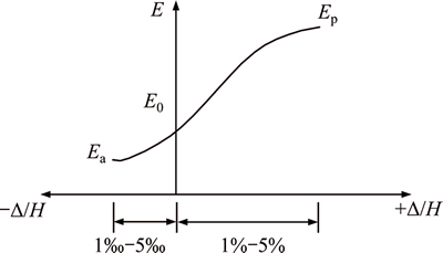
Fig. 9 Variation of soil pressure with displacement of retaining wall
XU [19] presented a calculation method of earth pressure related to displacement as follows.
Active earth pressure:
 (20)
(20)
Passive earth pressure:
 (21)
(21)
where ��0 is the static earth pressure; �� is the displacement of soil (positive value is selected); ��arc is the active limit displacement of soil; ��prc is the passive limit displacement of soil; ��arc is the active earth pressure in limit equilibrium state and ��prc the passive earth pressure in limit equilibrium state.
From Eqs. (20) and (21), if the soil displacement �� equals its active limit displacement ��arc, the calculated earth pressure is the active limit earth pressure ��arc; if the soil displacement �� equals its passive limit displacement ��prc, the calculated earth pressure is the passive limit earth pressure ��prc.
4 Case study
4.1 Overview
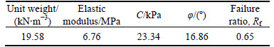
To verify the practicability and feasibility of the theory in this work, the theoretical results are applied to a foundation pit project in Tianjin, China [20] and compared with the measured data obtained from the excavation. The foundation pit is 21 m in depth and 80 m in width, with reinforced concrete cast-in-situ piles as the supporting structure. In addition, cement mixing piles (32 m long and 11 m in buried depth) and TRD method are used around the pit for sealing, along with four horizontal braces for additional support. In calculating the stress or displacement in the semi-infinite body, relevant parameters and geological conditions of the project are used. For ease of calculation, the layered soil is regarded as homogeneous soil, that is, average values of soil parameters are adopted. The homogenized soil parameters are shown in Table 1. The soil is assumed to be a continuous medium without regarding soil failure.
Table 1 Physical and mechanical properties of soil
4.2 Analysis of calculation results
Figure 10 shows the distribution of loading and unloading zones after deformation as a result of excavation. Zone I and Zone II are unloading zones, i.e., ��(��1-��2)<0. As can be seen from Fig. 2, the tangent modulus Et in these zones increases, and the unloading zone covers the entire Zone II within the range of buried depth of the pile foundation, which agrees with the conclusion reached by PAN et al [21] and SUN [22]. The influence range of unloading below the bottom of the foundation pit is 1.33 times of the excavation depth. Any zone other than Zones I and II in the figure is the loading zone.
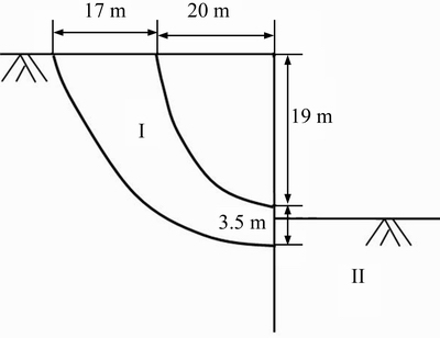
Fig. 10 Distribution of loading and unloading zones of soil
Figures 11 and 12 show the settlement of soil around the foundation pit and bottom upheaval, respectively. As can be seen from Fig. 11, the calculated results with the model in this work present a trend roughly consistent in horizontal direction with that of the measured data, and the values of settlement are basically the same. The maximum settlement of soil around the foundation pit calculated from the model is 31.2155 mm and occurs 4.5 m away from the edge of the pit, while the maximum measured settlement is 27.5 mm and occurs 10 m away. These deviations might be attributed to the use of homogeneous soil and the method where only elasticity is considered. In Fig. 12, bottom upheaval increases as it moves closer to the middle of the pit until it reaches a maximum of 40.096 mm, which is in agreement with the measured maximum of 45.1 mm. By substituting the calculated value of displacement into the calculation formula of earth pressure related to displacement, as shown in Fig. 13, the earth pressure is obtained after excavation, which falls between the static earth pressure and the active earth pressure.
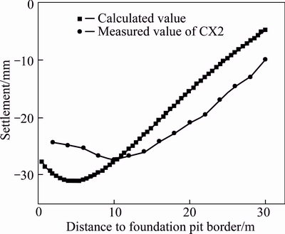
Fig. 11 Settlement of soil around foundation
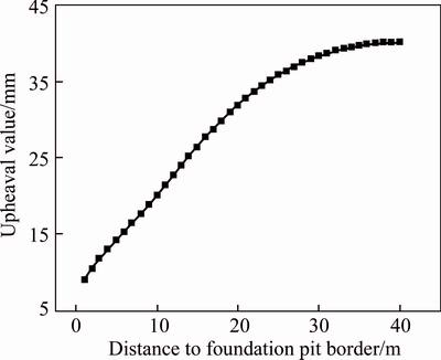
Fig. 12 Bottom upheaval
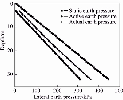
Fig. 13 Lateral earth pressure of soil around foundation
5 Conclusions
1) A calculation model for foundation pit deformation during excavation is suggested. And the stress solution of elastic semi-infinite space under horizontal non-uniformly distributed linear load is obtained to determine the stress state of each point in the foundation pit. The modulus of relevant points is obtained, with which the deformation of the foundation pit is modified. Then, the earth pressure after deformation is calculated, which contributes to more reliable calculation results.
2) The theoretical analysis model of this work is applied to an actual foundation pit project for numerical analysis of the excavation process, and the calculated results are close to the measured results, proving the feasibility and practicability of the proposed model.
References
[1] LADD C C. Stress-deformation and strength characteristics: State of the art report [C]// International Conference on Soil Mechanics and Foundation Engineering. 1977: 18�C20.
[2] LIU Guo-bin, HOU Xue-yuan. Unloading modulus of the Shanghai soft clay [J]. Chinese Journal of Geotechnical Engineering, 1996, 18(6): 18-23. (in Chinese)
[3] HSIEH P G, CHANG Y O, LIU H T. Basal heave analysis of excavations with consideration of anisotropic undrained strength of clay [J]. Canadian Geotechnical Journal, 2008, 45(6): 788-799.
[4] CUI Y J, NGUYEN X P, TANG A M, LI X L. An insight into the unloading/reloading loops on the compression curve of natural stiff clays [J]. Applied Clay Science, 2013, 83�C84: 343-348.
[5] TANAKA H, TSUTSUMI A, OHASHI T. Unloading behavior of clays measured by CRS test [J]. Soils and Foundations, 2014, 54(2): 81-93.
[6] HSIEH P G, CHANG Y O, LIU H T. Basal heave analysis of excavations with consideration of anisotropic undrained strength of clay [J]. Canadian Geotechnical Journal, 2008, 45(6): 788-799.
[7] ZHOU Qiu-juan, CHEN Xiao-ping. Test research on typical mechanical characteristics of soft clay under lateral unloading condition [J]. Chinese Journal of Rock Mechanics and Engineering, 2009, 28(11): 2215-2221. (in Chinese)
[8] MESRI G, ALI S. Undrained shear strength of a glacial clay over consolidated by desiccation [J]. Geotechnique, 1999, 49(2): 181-198.
[9] JAHANANDISH M, BEPOOR L, GHAHRAMANI A. Load displacement characteristics of retaining walls [C]// Publications Committee of XII ICSSMFE Staff. Proceedings of the Twelfth International Conference on Soil Mechanics and Foundation Engineering. Rotterdam, Dutch: A. A. BALKEMA, 1989: 243-246.
[10] MEI Guo-xiong, CHEN Qi-ming, SONG Lin-hui. Model for predicting displacement dependent lateral earth pressure [J]. Canadian Geotechnical Journal, 2009, 46(8): 969-975.
[11] FANG Y S, ISHIBASHI I. Static earth pressure with various wall movement [J]. Journal of Geotechnical Engineering, 1986, 112(3): 317-333.
[12] FANG Y S, CHEN T J, WU B F. Passive earth pressures with various wall movements [J]. Journal of Geotechnical Engineering, 1994, 120(8): 1307-1323.
[13] CHEN L. Active earth pressure of retaining wall considering wall movement [J]. European Journal of Environmental and Civil Engineering, 2014, 18(8): 910-926.
[14] WEI Huan-wei, YANG Min, JIA Qiang, SUN Jian-ping. Calculation model of soil pressure displacement based on Mindlinsolution [J]. Rock and Soil Mechanics, 2011, 32(2): 495-502. (in Chinese)
[15] MA Shao-jun, WANG Kui-hua, WU Wen-bing. Pseudo-dynamic active earth pressure behind retaining wall for cohesive soil backfill [J]. Journal of Central South University, 2012, 19(5): 3298-3304.
[16] ZHU Qi-yin, YIN Zhen-yu, XU Chang-jie, YIN Jian-hua, XIA Xiao-he. Uniqueness of rate-dependency, creep and stress relaxation behaviors for soft clays [J]. Journal of Central South University, 2015, 22(1): 296-302.
[17] YIN De-shun, WANG Bao-tian, WANG Yun-tao. Tangent elastic modulus of Duncan-Chang model for different stress paths [J]. Chinese Journal of Geotechnical Engineering, 2007, 29(9): 1380-1385. (in Chinese)
[18] WANG Zhi-liang, YIN Zong-ze, LI Yong-chi. Practical method for FEM analysis of embankment settlement with duncan-chang model [J]. Rock and Soil Mechanics, 2005, 26(7): 1085-1089. (in Chinese)
[19] XU Ri-qing. Methods of earth pressure calculation for excavation [J]. Journal of Zhejiang University: Engineering Science, 2005, 39(1): 119-122. (in Chinese)
[20] DUAN Xian-ming. Behavior of pile foundation during deep excavation [D]. Tianjin: Tianjin University, 2013. (in Chinese)
[21] PAN Lin-you, CHENG Yu-mei, HU Zhong-xiong. Experimental study on the shear strength of clay under the unloading state [J]. Rock and Soil Mechanics, 2001, 22(4): 490-493. (in Chinese)
[22] SUN Xiu-zhu. Relationship between change of stress field and depth of influence for unloading [J]. Site Investigation Science and Technology, 2004(4): 12-15. (in Chinese)
(Edited by FANG Jing-hua)
Cite this article as: HUANG Ming, LIU Xing-rong, ZHANG Nai-yang, SHEN Qi-wei. Calculation of foundation pit deformation caused by deep excavation considering influence of loading and unloading [J]. Journal of Central South University, 2017, 24(9): 2164�C2171. DOI:https://doi.org/10.1007/s11771-017-3625-3.
Foundation item: Project(41672290) supported by the National Natural Science Foundation of China; Project(2016J01189) supported by the Natural Science foundation of Fujian Province, China
Received date: 2015-09-30; Accepted date: 2016-05-11
Corresponding author: HUANG Ming, PhD, Associate Professor; Tel: +86-18659191796; E-mail: huangming05@163.com

