Design and implementation of robot serial integrated rotary joint with safety compliance
��Դ�ڿ������ϴ�ѧѧ��(Ӣ�İ�)2017���6��
�������ߣ�� ��˧ ��˼�� ������
����ҳ�룺1307 - 1321
Key words��elastic element; impedance control; safety compliance; active compliance; serial integrated rotary joint
Abstract: In order to guarantee safety and stability during physical human-robot-interaction (pHRI) in the occasion of service or industrial operation, a serial integrated rotary joint with the characteristics of passive and active compliance is proposed. Passive compliance is achieved by a designed elastic element, such that the compliant joint may minimize large force which occurs during accidental impacts and, further, may offer more accurate and stable force control and a capacity for energy storage. Meanwhile, the modeling of the compliant joint is comprehensively analyzed, including the effect of the motor model on the overall control system. In order to realize the active compliance, a new method of impedance control is proposed. On the basis of PD control, a more compliant impedance controller is introduced. Experimental results show that the serial integrated rotary joint can provide more effective safety compliance during physical interaction, which has also been well applied in our designed massage robot and rehabilitation robot.
Cite this article as: LI Shuai, LI Jian, LI Si-qi, HUANG Zong-lin. Design and implementation of robot serial integrated rotary joint with safety compliance [J]. Journal of Central South University, 2017, 24(6): 1307-1321. DOI: 10.1007/s11771-017-3536-3.
J. Cent. South Univ. (2017) 24: 1307-1321
DOI: 10.1007/s11771-017-3536-3

LI Shuai(��˧)1, LI Jian(�)2, LI Si-qi(��˼��)1, HUANG Zong-lin(������)1
1. School of Mechatronical Engineering, Beijing Institute of Technology, Beijing 100081, China;
2. School of Automation, Beijing Institute of Technology, Beijing 100081, China
 Central South University Press and Springer-Verlag Berlin Heidelberg 2017
Abstract: In order to guarantee safety and stability during physical human-robot-interaction (pHRI) in the occasion of service or industrial operation, a serial integrated rotary joint with the characteristics of passive and active compliance is proposed. Passive compliance is achieved by a designed elastic element, such that the compliant joint may minimize large force which occurs during accidental impacts and, further, may offer more accurate and stable force control and a capacity for energy storage. Meanwhile, the modeling of the compliant joint is comprehensively analyzed, including the effect of the motor model on the overall control system. In order to realize the active compliance, a new method of impedance control is proposed.On the basis of PD control, a more compliant impedance controller is introduced. Experimental results show that the serial integrated rotary joint can provide more effective safety compliance during physical interaction, which has also been well applied in our designed massage robot and rehabilitation robot.
Key words: elastic element; impedance control; safety compliance; active compliance; serial integrated rotary joint
1 Introduction
With the accelerating demand for robots, traditional ones with high stiffness characteristics in some occasions are not suitable, such as industrial grinding, trimming, casting robots, usually accompanied by heavy load and impact, or service robots with physical human-robot- interaction (pHRI). When a robot in motion accidentally collides with human, there will be a great impact on the human body, which may cause injured. Therefore, many scholars proposed the concept of compliance.
In the growing fields of wearable robotics, rehabilitation robotics, prosthetics, and walking robots, variable stiffness actuators (VSAs) or adjustable compliant actuators are being designed and implemented because of their ability to minimize large forces due to shocks, to safely interact with the user, and their ability to store and release energy in passive elastic elements. The designs are divided into four groups: equilibrium-controlled stiffness, antagonistic-controlled stiffness, structure-controlled stiffness (SCS), and mechanically controlled stiffness [1]. PRATT and WILLIAMSON [2] first proposed serial elastic actuator. Compared with the traditional one, an elastic element is added, which is mainly composed of a spring, and when subjected to an external load, the joint can produce compliance by the spring. SENSINGER and WEIR [3] proposed the serial elastic actuator that can provide the appropriate speed and stability of the torque; The main feature is the use of inner loop control to make the elastic element maintain a stable torque. HUTTER et al [4] developed ScarlETH (a series compliant articulated robotic leg was developed at ETH Zurich) and through the joint compliance to achieve the bionic movement, it can temporarily store energy, and improve the ability of passive adaptability. KONG et al [5] created a serial compliant joint actuator, which is somewhat different from the mentioned above that the elastic element is added to the input side of the reducer, which has the advantages of small size and compact structure; However, angular displacement of the input side, which is connected with the motor shaft, is n (reduction ratio) times that of the output, and the torque of the input is 1/n times that of the output. So, the stiffness of the spring on the input side is 1/n2 times the stiffness of a spring on the output side; The stiffness of the spring on the input side is greatly reduced; The energy stored in the spring is limited. Robotic arms with compliant joints, such as DLR lightweight arm [6], iCub [7], Meka compliant arm [8], Cog [9], exhibit both superiority on safety during human-robot impacts and good performance. In addition,Foundation item: Project(81473694) supported by the National Natural Science Foundation of China; Project(2016A1027) supported by the major Project of Zhongshan City, China; Project(2016FZFC007) supported by the Intelligent Equipment and Technology of Automation Research and Development Platform, China there are some new materials used to develop a new type of driver as the progress of material technology, such as, memory alloy [10], electro rheological fluids (ERF) [11], electrostriction and magnetostrictive materials (including piezoelectric material) [12], electrically active polymer [13]. There is a great disadvantage in using these new materials to design a flexible driver that the response time is very long, and unsuitable for high-speed situation.
Passive compliance uses springs, damping and other mechanisms to achieve the compliance between robot and environment [14]. It was proposed that the use of elastic element can cause system with the characteristics of slow response, low position-control precision and so on [15-19]. The active compliance control is based on the external force feedback information collected by the robot, which can be achieved by a certain control algorithm, and mainly includes hybrid control of force/position and impedance control.
In order to render robotic arms with compliance and meanwhile guarantee safety, an integrated joint with series elasticity is designed for its low impedance can effectively decouple the link��s inertia from the actuator��s reflected inertia whenever impact occurs and, further, more accurate and stable force control and the capacity for energy storage [20, 21] can be offered.
2 Design of compliant joint
2.1 Structural design
A serial integrated rotary joint with standard electrical and mechanical interfaces is developed as a fundamental element for constructing the modular human-like service robot or industrial robot with intrinsic safety during the process of pHRI. A new type of serial elastic actuator (SEA) is proposed, which has high stability and safety.Motor, harmonic driver reducer and elastic element are connected in series. Meanwhile, control circuit boards are installed in the joint, with the characteristics of integration, modularity, compact structure and so on. Because the closed-loop control needs some feedback information of the system, such as the current position of the joint, the torque, it also needs sensors to return the position and the torque information.
Figure 1 shows the section view of the serial integrated rotary joint. It mainly consists of the elastic element, actuation unit, and circuit boards, integrating all electrical and mechanical components, such as equivalent torsional spring set (e.g., elastic element), electric motor, reducer (e.g., harmonic driver), rotary position sensors (e.g., photoelectrical incremental encoder), control and driving circuit boards, into a cylindrical shell and providing the standard electrical and mechanical interfaces (see Figs. 2 and 3), which can be interoperable and interchangeable with other joint modules.
The flexspline of the harmonic driver reducer as the output member, is connected with the elastic element in series. Finally, the output member of the elastic element is connected with the joint shaft (mechanical interfaces). In addition, on the right near side of the motor where a photoelectric encoder sensor is installed, which is used to measure the joint��s position information; While, another photoelectric encoder sensor in the elastic element is used to measure the joint��s torque information. The implementation detailed principle is described in Section 2.2 below. The explosive view of the compliant joint structure is shown in Fig. 4.
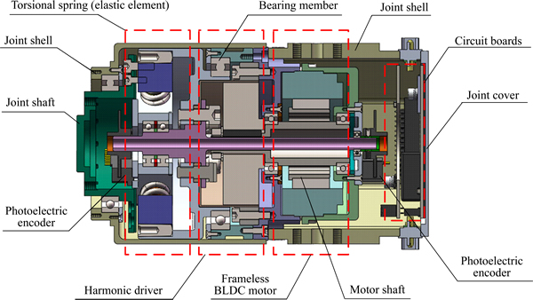
Fig. 1 Section view of serial integrated rotary joint composition

Fig. 2 Mechanical interface:
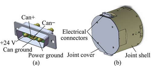
Fig. 3 Electrical connector (a) and mechanical layouts (b)
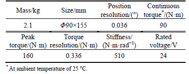
The technical specifications of the serial integrated rotary joint are shown in Table 1.
The purpose of integrated design is to make the user more convenient to assemble robot. So, a unique and reliable mechanical interface is provided in this compliant joint. As the same as the traditional joint, it also contains two parts. One is used to fix the joint, and the other is used as the interface with the next joint.
Table 1 Joint��s technical specifications
Electrical connector consists of power interface and CAN interface. Power interface can supply DC 24V. CAN protocol is implemented in FPGA. This integrated connector can communicate and be networked with other modules. Figure 3 shows the pin definitions of electrical connector.
2.2 Elastic element
The elastic element arranged between the actuation unit and the joint output shaft is crucial. It not only decomposes the rigid actuation unit from the joint output shaft, offering the passive compliance when the joint output shaft is impacted suddenly by external load, but also reflects the magnitude of the output torque by the deflection of springs. As shown in Fig. 5, input sectorial blocks and 8 linear springs are evenly positioned along a circumference. The elastic element shell is connected with the output flexspline of the harmonic driver. The deflected angle between the elastic element shell and the output spoke is measured by the photoelectrical incremental encoder installed on the output spoke. Analogous to that in Refs. [7, 22], the relationship between the rotational joint torque, T, and the deflected angle of the output spoke, ��s, can be derived as follows.

Fig. 4 Explosive view of compliant joint
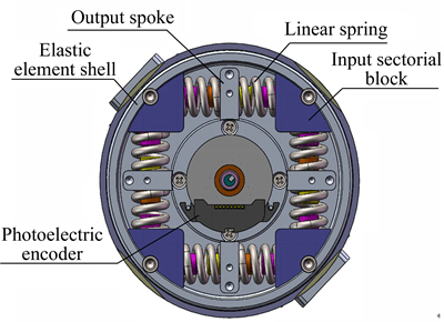
Fig. 5 Elastic element
As shown in Fig. 6, because the four groups of springs are uniformly distributed along the circumference, and each group is symmetrical distributed along an output spoke arm we only need to take one of the springs for analysis.
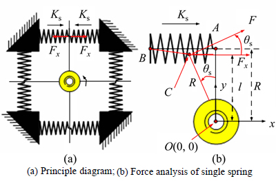
Fig. 6 Model analysis of elastic element:
The original length of the spring is x. When the springs are assembled, it is required to have a certain preload for them.Point A(0, R) is the equilibrium position of the output spoke after preloading, at which the length of the spring is xBA. When the spring is subjected to external force, the output spoke produces a deflection angle ��s relative to the elastic element shell. Point A is compressed to the point C and by this time, the length of the spring is xBC. The deformation of the spring is:
 (1)
(1)
The horizontal axial force generated by each spring when the output spoke deviates from the equilibrium position by the angle ��s is given by
 (2)
(2)
where Ks is the spring axial stiffness; R is the length of the output spoke arm. Therefore, the combined axial force applied in any spoke is approximately:
 (3)
(3)
The distance l between the direction of the force Fx and the center O (0, 0) is:
 (4)
(4)
So, if regardless of the spring diameter, the corresponding torque generated at this point due to the axial forces of one antagonistic pair of springs is equal to
 (5)
(5)
Actually, because the diameter of the spring is relatively large, about 15 mm, it cannot be ignored in the calculation. When subjected to external force, the spring��s deformation is not linear, meanwhile, the bending moment exists. It is not easy to get a precise mathematical model. So, the integral average method is used here and the relatively accurate expression is obtained.
 (6)
(6)
where rs is radius of the spring, while the diameter of the spring��s steel wire is not considered here. The four groups of springs are symmetrically and evenly distributed along the circumference, so the total output spoke torque can be obtained:
 (7)
(7)
When the angle ��s is smaller, the above formula can be approximated as
 (8)
(8)
By Eq. (8), it shows the relationship between the external torque and the rotation angle generated by the deformation. But in fact, the factors of springs�� processing error, assembly error and so on, make the stiffness coefficient inaccurate, resulting in a fact that the torque measurement is not accurate; therefore, it is necessary to calibrate the stiffness of the elastic element. The specific calibration work is implemented in Section 6. According to Eq. (8), with the known load torque ��ext and the measured angle ��s, the spring stiffness is:
 (9)
(9)
Taking the parameters ��ex=120 N��m, ��s=7.5�� into above formula, the spring stiffness is calculated as Ks= 128.267 N/mm. The physical photographs of the serial integrated rotary joint and the elastic element are shown in Fig. 7.
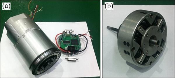
Fig. 7 Serial integrated rotary joint (a) and elastic element (b)
3 System analysis and modeling
As the elastic element is used in the serial integrated rotary joint, the modeling of the joint is more complicated than the traditional rigid one. It is necessary to carry out the comprehensive modeling, and analyze the stability conditions of the system. The stiffness k of the serial system satisfies the following formula:
 (10)
(10)
As shown in Fig. 8, the elastic element is equivalent to a torsion spring. The stiffness of the link and the harmonic reducer is much larger than that of the equivalent torsional spring composed of the linear springs.Therefore, in the establishment of the joint control model, we only need to consider the stiffness of the equivalent torsional spring.

Fig. 8 Schematic diagram of compliant joint
When only considering the effect of the elastic element on the stability of the system, the modeling of the brushless DC motor and the harmonic reducer can be ignored and they can be seen as a whole. The equivalent model obtained by further simplification is shown in Fig. 9.
The overall equivalent model is divided into three parts, respectively, the driver module, which is composed of a brushless DC motor and a harmonic wave, the inertia B on the left side of the equivalent torsional spring, and the load inertia M on the right side. The equivalent torsional spring is located between B and M.
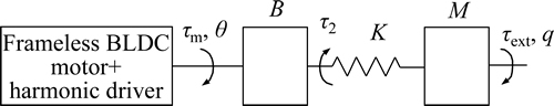
Fig. 9 Equivalent model of serial integrated rotary joint
3.1 Stability analysis of compliant joint
Assuming that the rotation angle on the left side of the equivalent torsional spring is ��, the rotation angle of the output link is q, so the torque is:
 (11)
(11)
where K is the stiffness of the equivalent torsional spring. On the left side of the torsion spring, balance equation can be listed as follows:
 (12)
(12)
where ��m is output torque of motor after amplification by harmonic reducer. Similarly, on the right side of the torsion spring, the balance equation is as follows:
 (13)
(13)
where ��ext is load torque. Putting Eq.(11) into Eq. (13), there is:
 (14)
(14)
That is:
 (15)
(15)
Two differential equations can be obtained by Eq. (15):
 (16)
(16)
 (17)
(17)
The control law ��m is written as
 (18)
(18)
where v is an intermediate control input variable:

Ba is the proportional control parameter of the torque control loop; Ds is the differential control parameter; kp and kd are the proportional and the differential coefficient respectively. And from Eqs.(18) and (12), there is:
 (19)
(19)
Putting Eqs. (16), (17) into (19), we have

 (20)
(20)
Putting the intermediate control input variable v into above formula yields:

 (21)
(21)
After the Laplace transform of the above formula, there is:

 (22)
(22)
According to the Routh criterion, the stability condition of the system is obtained.
 (23)
(23)
According to the last inequality above, when kd satisfies:

the value of kp can reach the maximum:

3.2 Steady-state analysis
According to Eq. (21), this system can be regarded as the linear superposition of the two subsystems. The first subsystem ��1 satisfies the following relationship:
 (24)
(24)
Assuming that the input is qd, and the output is q,the closed-loop transfer function of the system can be obtained:
 (25)
(25)
The second subsystem ��2 satisfies the following formula:

 (26)
(26)
Assuming that the input is ��ext, and the output is q, the closed-loop transfer function of the system can be obtained:
 (27)
(27)
By the superposition principle of linear system, the transfer function of the system can be obtained:
 (28)
(28)
Figure 10(a) shows is the torque feedback block diagram according to the control law mentioned above, which contains the torque feedback ��s Eq. (11), and after the above derivation, the block diagram of the whole control system through superposition and simplification is shown in Fig. 10(b).
Assuming that the equilibrium position of the system is qd=0, ��ext is the input, and q is the output, so:

The stiffness of the system is:
 (29)
(29)
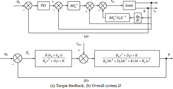
Fig. 10 Control block diagram:
So, there is:
 (30)
(30)
The response of the system is:
 (31)
(31)
1) Steady state error of system under pulse input
The pulse function is ��(t)=��(t). After Laplasse transform, there is ��(t)=1, so the steady state error of the system is:


 (32)
(32)
2) Steady state error of system under step input
The step function is ��(t)=��0(t), t��0. After Laplasse transform, there is ��(t)=��/s, the steady state error of the system is:

 (33)
(33)
Stiffness of system is K�� =��0/Ess=kp.
3) Steady state error of system under input of slope function
The slope function is ��(t)=t, t��0. After Laplasse transform, there is ��(t)= ��/s2, so the steady state error of the system is:


which shows that the error is infinite now.
3.3 Motor��s effect on system
Taking the actual situation into account, the motor has a certain effect on the system, so it is necessary to carry out a comprehensive system analysis. Meanwhile, the effect of integral term in the current loop on the system also should be analyzed.
3.3.1 Model of brushless DC motor
A three-phase brushless DC motor (Kollmorgen) is used and the motor stator winding is in the form of ��Y�� connection. In order to obtain the simplified model, the following assumptions are given.
1) Eddy current loss and hysteresis loss of DC brushless motor can be ignored;
2) Cogging brushless DC motor can be ignored;
3) The counter electromotive force of the brushless DC motor is the trapezoidal wave.
The phase voltage of the DC brushless motor is mainly composed of two parts. One is the voltage drop of self resistance, and the other is the induction electromotive force, which can be expressed as

where uA, uB, uC are three-phase windings voltages; RA RB, RC are three-phase winding resistances, and let RA=RB=RC=R; iA, iB, iC are phase currents; e��A, e��B, e��C are three-phase induced electromotive forces.
Taking the ��A�� phase winding of Brushless DC motor as an example, the magnetic linkage is:

where LA is ��A�� phase winding��s self-inductance; MAB, MAC are the inductions of ��B�� phase and ��C�� phase relative to ��A�� phase winding; �� is the angle between the rotor of the motor and the axis of the A phase winding; ��pm(��) is the permanent magnetic flux linkage of ��A�� phase winding magnetic linkage. The magnetic flux distribution of the brushless DC motor can be expressed in Fig. 11.
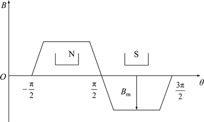
Fig. 11 Magnetic flux distribution
When the motor rotor is rotating, the effective magnetic flux of the ��A�� phase winding magnetic linkage changes with the rotor angle. When the angle between the rotor and the direction of ��A�� phase winding magnetic field is ��, the permanent magnetic flux linkage of ��A�� phase winding magnetic linkage is:

where N is the number of turns of winding; B(��) is the distribution of magnetic induction density of the permanent magnet rotor radial air gap, and the DC brushless motor is trapezoidal distribution; S is the enclosed area of the winding in the stator inner diameter��s surface. ��A�� phase��s induced electromotive force can be obtained by the differential equation of the above formula:

And then there is:


Let,  , so,
, so,
Because the three-phase winding of the stator of the brushless DC motor is symmetrical structure, LA=LB=LC= L, MAB=MBA=MBC=MCB=MAC=MCA, so there is:


Due to a fact that the three-phase current satisfies: iA=iB=iC=0, the above equation can be further simplified as

In the same way, similar results can be obtained from the ��B�� and ��C�� phases, so the matrix form of the three-phase voltage equation of the brushless DC motor can be expressed as

 (34)
(34)
3.3.2 Current loop without integral term
According to the characteristics of brushless DC motor, there is:
 (35)
(35)
where i is the motor phase current; Kt is the motor torque constant; R is the harmonic reduction ratio. According to Eq. (34), without consideration of the effect of mutual inductance, the formula can be further written as
 (36)
(36)
The control laws of position loop, control loop and current loop are given as
 (37)
(37)
Putting Eq. (35), and the current loop of Eq. (37) into Eq. (36) yields:

 (38)
(38)
In the steady state, the above formula can be written as

That is:
 (39)
(39)
Putting Eq. (12), and the torque loop of Eq. (37) into above Eq. (39), there is:


In the steady state, there is:

Supposing ��s as the input variable, the output is obtained by subtracting the actual angle and the expected angle. So, the result is:

From the above result, when considering the model of the brushless DC motor, if the current loop does not use integral term, it will cause the system to reduce the stiffness of the system, that is, K
3.3.3 Current loop with integral term
Now, integral term is considered to add into the current loop to analyze the impact of the system stiffness. The control law can be written as
 (40)
(40)
The differential of the current loop in Eq. (40) is obtained as follows:

In the steady state, there is:

According to Eq. (35) and the above formula, there is, ��d=��m. Putting Eq. (12) into the torque loop of Eq. (40), there is:

Supposing ��s as the input variable, the output is obtained by subtracting the actual angle and the expected angle. So, the result is:

It can be seen from the above formula, when considering the DC brushless motor model, if integral term is used in the current loop, the stiffness of the system can be improved, which is equal to parameter Kp of the position loop.
4 Simulation
4.1 Stability and steady-state verification
Based on the above analysis, simulation model in Matlab/Simulink is built. The input parameters of the simulation are shown in Table 2, corresponding to the simulation model in Fig. 12. Firstly, according to the stability condition of Eq. (23), the appropriate control parameters are selected, and different response curves can be obtained by selecting different parameters. In addition, in order to better reflect the dynamic characteristics of the system, at the simulation time of t=3 s, an external torque of step signal is applied, with the value of ��ext=10 N��m. The stability conditions of the system are verified.
When Ba=0.076, Ds=5, according to the stability condition of the system, let kd=Ds (Ba+M)/2Ba=5.8, the system stiffness kp satisfies: kp��K(Ba+M)2/4BaM=710.43. Different values of kp were given, and the system response curves were obtained as shown in Fig. 13.
It can be seen from the above simulation results that When kp=10, the system is in the underdamped condition;there is no overshoot; an external force is exerted at t=3 s; system can respond quickly and soon enter into steady state. However, due to a fact that the stiffness kp is relatively small at this time, when there is an external force, the system has a large steady-state error, with the value of 68��; while, this case is not allowed where the position control precision is required high. When kp=50, the system is still in the underdamped condition, but the response characteristic is obviously better than that at kp=10. The system not only has no overshoot, but also the rise time is also reduced a lot and the rapidity of the system is also improved. Most important of all, when the external force is exerted to the system, the steady-state error is greatly reduced. When kp=80, the system starts to have overshoot. Although the rise time decreases, in many cases, overshoot is not allowed. With the increasing of kp, the steady-state error of the system under external force is smaller and smaller. When kp is close to 710, concussion phenomenon begins to appear. Until kp>710.43, the system begins to be unstable and is in a state of divergence.
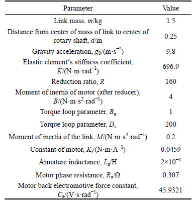
Table 2 System parameters

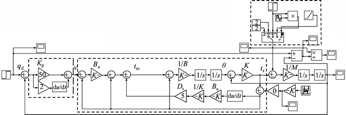
Fig. 12 Simulink simulation model
The steady-state error of the system is verified by the same simulation method.According to the analysis above, the final conclusion is that the system stiffness approaches to kp. According to the stability condition, kp satisfies kp��K(Ba+M)2/(4BaM)=710.43 and by choosing different value of kp to simulate and verify, finally the simulation conclusion is got that the system stiffness is equal to kp.

Fig. 13 Simulation result:
4.2 Integral term��s effect on system stiffness
In order to verify the correctness of the system steady-state analysis after adding the current loop with integral term, a simulation model is built in Matlab/ Simulink. And the simulation parameters are shown in Table 3.
Table 3 System simulation parameters
Through the above analysis, the stiffness of the system K satisfies the following relationship:
In order to verify this result, different control parameters were selected to carry out the verification simulation. Here taking the parameters Kp=853.9, Kpi=0.42, Kii=1 for example, based on theoretical analysis, the system stiffness K=Kp=853.9. The result is shown in Fig. 14.

Fig. 14 System stiffness simulation
5 Impedance control
The impedance control is the dynamic relationship between force and displacement of the robot end-effector, which can be achieved by adjusting the parameters.
When subjected to external force, the robot can show the characteristic of impedance, which is similar to the role of an elastic spring. The control block diagram of impedance control is shown in Fig. 15.

Fig. 15 Impedance control block diagram
As seen from above figure, the control system is composed of two parts. One is the position controller, and the other is the impedance controller. The function of the impedance controller is to calculate ���� with the measured torque, position information of the joint. When an external force is exerted to the joint, the overall control system can show a certain compliance and the joint will output the corresponding displacement by the impedance controller. The greater the external force is, the larger the generated displacement will be, and vice versa. When the external force disappears, the output of the impedance controller is 0, and the system is kept in the state of original impedance characteristic.
From Eq. (18), control law is written as follows:

where kp is the proportional parameter of position loop; kd is the differential parameter; Ba is the proportional parameter of torque loop; Ds is the differential parameter. The impedance controller is using the following equation:

where K is the stiffness coefficient, D is the damping coefficient, and M is the inertia coefficient.
6 Experimental verification
6.1 Experimental platform
As shown in Fig. 16, the platform mainly consists of a serial integrated rotary joint, a support frame, a link and metal plate loads.

Fig. 16 Experimental platform
The rotary joint is mounted on the support frame by the screws, and the mechanical output interface of the joint is connected with the link, whose length is 0.5 m. The metal plate load��s mass is 3 kg, which can be mounted on one third or two thirds of the link, such that to obtain different torques, as shown in Fig. 17.
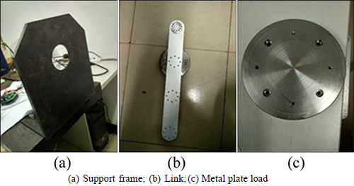
Fig. 17 Components of platform:
6.2 Torque calibration
The control system needs the joint��s torque information when the closed-loop control is carried out. So, the measurement precision of the torque sensor directly affects the dynamic performance and the steady state of the control system. Actually, due to the existence of machining and assembly errors, which can eventually lead to the deviation of the measured torque values, it is necessary to carry out the torque calibration of the designed elastic element. Different values of loads are applied to the output of the joint, and the torque values can be obtained through the measurement of axis force sensor. The rotation angle of the elastic element can be measured by the position sensor.
Putting Ks=128.267 N/mm, R=32 mm, and rs=7.7 mm into Eq. (7), the theoretical calculation formula of the relationship between torque and rotation angle can be obtained:

where �� is the measured rotation angle of the elastic element.
As shown in Fig. 18, the red line represents the theoretical calculation torque, while the black, blue and green dotted lines represent three times experiments. The relationship between torque and angle is almost linear, which can be fitted by linear curve. There is an error between the curve obtained by the actual sensor measurement and the theoretical calculation curve. From the specific experimental data, the maximum error is 4.7% of the maximum range and the repeatability error of measured torque is 1.08% of the maximum range.
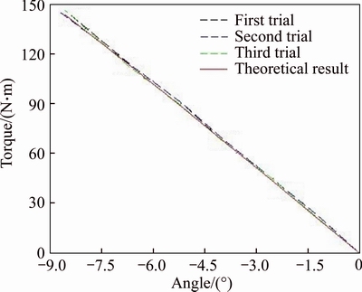
Fig. 18 Torque calibration of serial integrated rotary joint
6.3 Impedance control
In the service occasions of human-robot physical contact, or in the industry occasions of cutting, polishing and so on, robots are usually required to have greater safety compliance. Impedance control mode was adopted, which makes the serial integrated rotary joint have a larger range of impedance adjustment. The traditional impedance control method, that is the PD controller, is based on position, which cannot meet the compliance requirements. The impedance controller satisfies:

where K is the stiffness of the impedance controller; D is the damping coefficient. The two parameters can be arbitrarily selected; However, the different values selected will produce different effects. Here we give an example. Taking K=1.5, D=150 into the above formula, the obtained curve is shown in Fig. 19. In 0-2 s, the link of the rotary joint is in the initial position of the vertical downward, and then makes the joint rotate to the desired angular displacement of qd=90�� in position control mode. When it reaches a state of force balance, the control mode is changed to the impedance control at t=8 s, and then the joint rotates downward at once to a position of less than qd=90��; when it and reaches another state of force balance, the position deviation is ��q=12��, which is mainly affected by the stiffness coefficient K, who has a large adjustment range. The damping coefficient of the impedance controller D will affect the dynamic performance of the system. The greater the value of D is, and the more stable the system will be; however, if D is too large, it also will cause the system instability.
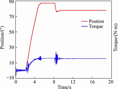
Fig. 19 Impedance control curve without external torque
As shown in Fig. 20, at t=4 s, the mode is switched to the impedance control mode, with the parameters K=1.5, D=150, and the joint arrives to a new balance position. When at t=7 s, upward and downward forces are exerted to the end of the joint link alternately and repeatedly by an operator. It can be seen that the system can well show the characteristic of the impedance, which is like an elastic spring that the operator can pull and press at the end of the link. When a downward force is exerted, and finally the generated torque reaches 40 N��m, the link is off the horizontal position about 30��. At this time, it is difficult to continue to press down the link. Under the external force, the system could respond well, and the movement is stable, which satisfies the design requirements. The experimental scenario is shown in Fig. 21.
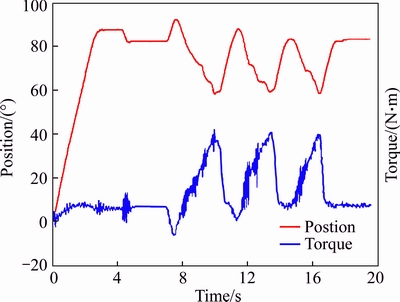
Fig. 20 Impedance control curve subjected to an external torque
7 Application
A 4-DOF robotic arm with ceramic massage head was constructed by the serial integrated rotary joints to do the massage both in sitting and lying scenarios, as shown in Fig. 22, which can be applied to home service and medical treatment. The satisfaction of robot massage and similarity to the human therapists are evaluated by the subjects. Statistical results show that about 95% of the subjects give positive evaluation. The simplified nonlinear H�� controller [23] is used to control the linearization of the compliant joint robot, and has a good effect. Figure 22(c) describes a scenario that the robot can provide compliance when it collides with human in motion, instead of directly producing a hard impact.
And also, a humanoid two-armed robot, similar to the structure of Baxter robot [24], was implemented with the serial integrated rotary joints, as shown in Fig. 23, which can provide a solution for a wide range of tasks �C from line loading and machine tending, to packaging and material handling. It also can be applied to home service, e.g. nursing care, housework, etc. Figure 23(b) shows that the robot is doing leg rehabilitation for a patient.
8 Conclusions
1) An elastic element was designed, which is composed of eight linear springs. On one hand, it can make the compliant joint minimize large forces which occur during accidental impacts, not only for the robot itself is a kind of protection, but also for the human is safe; On the other hand, joint torque can be measured by the elastic element, which can be used to implement force control and impedance control.

Fig. 21 Experimental scenario:
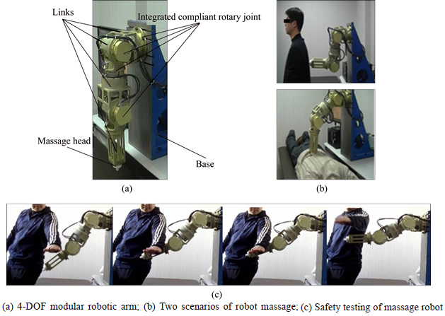
Fig. 22 Robot massage with 4-DOF modular robotic arm:
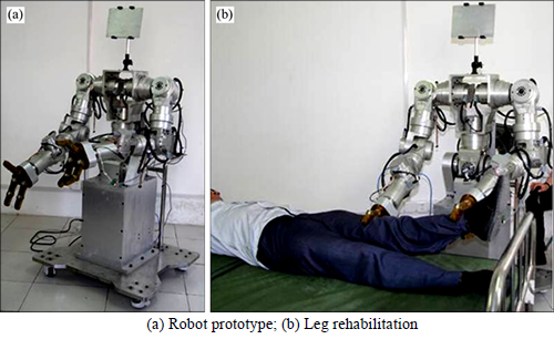
Fig. 23 Humanoid two-armed robot with serial integrated rotary joints:
2) Through modeling, the system��s stability conditions were obtained according to the Routh criterion; meanwhile, theoretical analysis and simulation were carried out for steady-state response of system. The conclusion is that the stiffness of the impedance control is shown to be equal to the parameter Kp of the position loop. In addition, taking the actual situation into account, the brushless DC motor was modeled, and after a comparative analysis, the result shows that, in the current loop, the existence of integral term or not will affect the system stiffness. When it exists, the system stiffness can be improved, which is equal to the parameter Kp. Finally, simulation and verification were carried out by Matlab/Simulink.
3) Impedance control was realized. The controller is composed of position loop PD control, torque loop and current loop, whose function is to calculate ���� with the measured torque, position information of the joint. When an external force is exerted to the joint, the joint will output the corresponding displacement by the impedance controller, which shows certain compliance. The greater the external force is, the larger the generated displacement will be, and vice versa.
4) Finally, experimental platform was set up. Through a lot of experiments, the results show that the designed the serial integrated rotary joint can provide safety compliant and has good control performance, which is also well applied to the massage robot and rehabilitation robot designed by our laboratory.
References
[1] HAM R V, SUGAE T G, VANDERBORGHT B, HOLLANDER K W. Compliant actuator designs [J]. IEEE Robotics & Automation Magazine, 2009, 16(3): 81-94.
[2] PRATT G A, WILLIAMSON M M. Series elastic actuators [C]// Proceedings of the IEEE/RSJ International Conference on Intelligent Robots and Systems. Pittsburg, PA: IROS, 1995: 399-406.
[3] SENSINGER J W, WEIR R F. Design and analysis of a non- backdrivable series elastic actuator [C]// Proceedings of the 2005 IEEE 9th International Conference on Rehabilitation Robotics. Chicago, IL, USA: IEEE, 2005: 390-393.
[4] HUTTER M, REMY C D, HOEPFLINGER M A, SIEGWART R. ScarlETH: Design and control of a planar running robot [C]// 2011 IEEE/RSJ International Conference on Intelligent Robots and Systems. San Francisco, CA, USA: IEEE, 2011, 10(1): 562-567.
[5] KONG K, BAE J, TOMIZUKA M. A compact rotary series elastic actuator for knee joint assistive system [C]// IEEE International Conference on Robotics and Automation. Anchorage, Alaska, USA: ICRA, 2010: 2940-2945.
[6] GREBENSTEIN M, SCHAFFER A A, BAHLS T, CHALON M, EIBERGER O, FRIEDL W, GRUBER R, HADDADIN S, HAGN U, HASLINGER R, HOPPNER H, JORG S, NICKL M, NOTHHELFER A, PETIT F, REILL J, SEITZ N, WIMBOCK T, WOLF S, WUSTHOFF T, HIRZINGER G. The DLR hand arm system [C]// IEEE International Conference on Robotics and Automation. Shanghai, China: ICRA, 2011: 3175-3128.
[7] TSAGARAKIS N G, METTA G, SANDINI G, TSAGARAKIS N G, METTA G, SANDINI G, VERNON D, BEIRA R, BECCHI F, RIGHETTI L, SANTOS-VICTOR J, IJSPEERT A J, CARROZZA M C, CALDWELL D G. iCub: The design and realization of an open humanoid platform for cognitive and neuroscience research [J]. Advanced Robotics, 2007, 21(10): 1151-1175.
[8] DEYLE T. Meka robotics�� humanoid torso and anthropomorphic hands [EB/OL]. [2009-10-18]. http://www.hizook.com/blog/2009/ 10/18/ meka-robotics-humanoid-torso-and-anthropomorphic-hands.
[9] Brooks R. Overview of the Cog project��The motivation behind creating Cog is the hypothesis that: Humanoid intelligence requires humanoid interactions with the world [EB/OL]. [1996-08-05]. http://www.ai.mit.edu/projects/cog/OverviewOfCog/cog_overview.html.
[10] LOVCHIK C, DIFTLER M. The robonaut hand: A dexterous robot hand for space [C]// Proceedings of the IEEE International Conference on Automation and Robotics. Detroit, Michigan: IEEE, 1999: 907-912.
[11] OBERG E, MCCAULEY C J, HEALD R. Machinery��s handbook [M]. 26th edition. New York: Industrial Press, Inc., 2000.
[12] KANG C G, LEE B J, SON I X, KIM H Y. Design of a percussive massage robot tapping human backs [C]// Proc 16th IEEE International Conference on Robot & Human Interactive Communication. Jeju, Korea: IEEE, 2007: 962-967.
[13] JAYENDER J, PATEL R V, NIKUMB S, OSTOJI M. Modeling and control of shape memory alloy actuator [J]. IEEE Transactions Control System Technology, 2008, 16(2): 279-287.
[14] PUGH A. Robot sensors: International trends in manufacturing technology [M]. UK: IFS Publication Ltd, 1986.
[15] ROBERTS R K. The compliance of end effect or force sensors for robot manipulator control [D]. West Lafayette: Purdue University, 1984.
[16] PRATT J E. Virtual model control of a biped walking robot [R]. Cambridge: MIT Artificial Intelligence Laboratory, 1995.
[17] SENSINGER J W, WEIR R F. Improved torque ripple turning in harmonic drives through the union of two existing strategies [J]. IEEE Transactions on Mechatronics, 2006, 11(4): 457-461.
[18] SULZER J, PESHKIN M, PATTON J. MARIONET: An exotendon- driven, rotary series elastic actuator for exerting joint torque [C]// International Conference on Robotics for Rehabilitation. Chicago, IL: IEEE, 2005: 103-108.
[19] BLAYA J A, HERR H. Adaptive control of a variable-impedance ankle-foot orthosis to assist drop-foot gait [J]. IEEE Transactions on Neural Systems and Rehabilitation Engineering, 2004, 12(1): 24-31.
[20] PRATT J, KRUPP B, MORSE C. Series elastic actuators for high fidelity force control [J]. Industrial Robot: An International Journal, 2002, 29(3): 234-241.
[21] ROBINSON D W, PRATT J E, PALUSKA D J, PRATT G A. Series elastic actuator development for a biomimetic walking robot [C]// IEEE/ASME International Conference on Advanced Intelligent Mechatronics. Atlanta, GA: IEEE, 1999: 561-568.
[22] HUANG Yuan-can, RAN Chong-jian, LI Jian, LI Guo-dong. Integrated rotary compliant joint and its impedance-based controller for single-joint pressing massage robot [C]// IEEE International Conference on Robotics & Biomimetics. Guangzhou, China: IEEE, 2012: 1962-1967. (in Chinese)
[23] LIU Xiang-dong, YU Yin, LI Zhen, HERBERT H C I. Polytopic H�� filter design and relaxation for nonlinear systems via tensor product technique [J]. Signal Processing, 2016, 127(C): 191-205.
[24] JU Zhang-feng, YANG Chen-guang, MA Hong-bin. Kinematics modeling and experimental verification of baxter robot [C]// Proceedings of the 33rd Chinese Control Conference. Nanjing, China: CCC, 2014: 8518-8523. (in Chinese)
(Edited by YANG Hua)
Cite this article as: LI Shuai, LI Jian, LI Si-qi, HUANG Zong-lin. Design and implementation of robot serial integrated rotary joint with safety compliance [J]. Journal of Central South University, 2017, 24(6): 1307-1321. DOI: 10.1007/s11771-017-3536-3.
Received date: 2016-07-25; Accepted date: 2016-10-16
Corresponding author: LI Jian, Experimentalist; Tel: +86-13522915195; E-mail: yellowlightlee@163.com

