
Strain and stress analysis on Zn multicrystal film by XRD method
HUANG Wen-jun, Vincent JI
LIM UMR CNRS8006, ENSAM, 151, Boulevard de l’H?pital, 75013 Paris, France
Received 10 April 2006; accepted 25 April 2006
Abstract: A new method was denonstrated to determine stress in a single crystal for multicrystal material and this new method could be specially applied for any symmetric crystalline systems. The strain tensor ε was determined by the change of the metric tensor G before the initial state and after the deformed state in the crystal reference system. Then stress tensor at grain scale was calculated by the HOOK’s law. The stress evaluations were carried out in coarse grains of a thin galvanized coating on a steel substrate during tensile loading. This makes it possible to link the microstructure evolution to the elastic heterogeneity at grain scale or between the grains.
Key words: single crystal; stress analysis; zinc; multi-crystals; tensile loading
1 Introduction
Zinc coated steel sheets are widely used for automotive and household electrical applications because of zinc’s good corrosion protection. The sheets are often shaped by complex or high strain level forming operations[1-2]. An accurate understanding of their deformation and the damage mechanism of the coating is necessary for the optimization of sheet forming. Due to the galvanizing process, the microstructure of the coating is made of large flat zinc grains (of several millimeters in diameter), with one single grain of 10 μm in thickness. For this microstructure, the single crystal method is required for the stress analysis with X-ray diffraction (XRD) in the grain.
According to the stress analysis of cubic crystals on the grain scale of a single grain, the analysis of the stress in the hexagonal crystal structure, in such zinc coating, becomes extremely complex. Recently, a new method to determine strain and stress by XRD for single crystal material with any structure has been developed and put in practice. This method consists of measuring metric tensor G of the studied crystal in the crystal basis and allows us to carry out the strain and stress tensor on grain scale. This single crystal measurement method is applied to the multi-materials with coarse grains, the determined stresses correspond to second order stresses.
The aims of the study are to determine residual strain and stress level by XRD on the grain scale of a zinc coating; to follow strain and stress evolution by XRD in 4 adjoining grains under tensile loading; and to try to find the relationship between the microstructure and heterogeneity on the grain scale or between the grains.
2 Methodology development
XRD technique is used for stress determination in crystalline materials[3-5]. This method is based on the measurement of the lattice spacing d(hkl) of a {hkl} family plan such as an internal strain gauge[6]. Since the early 90’s of the 20th centenry, it has been possible to apply a XRD methodology of stress analysis to single crystal stress determination for a cubic crystalline system, but it has not been adapted to the case of non cubic crystalline systems, for example hexagonal compact systems. A new single crystal method applied in any crystalline systems must be developed.
2.1 Grains orientations
The key is to determine a passage matrix from a crystal reference to a sample reference. In Fig.1 n is the normal of a (h k l) plane in a grain. The pole figure of a (h k l) plan gives the couple angles (φ, ψ) in diffraction position. The three component coordinates of the normal n can be deduced from the couple angles (φ, ψ) in the sample reference.
In a non cubic structural crystal, an orthonormal reference was proposed associated with crystal reference (Fig.2). This proposition can bring the calculations in orthonormal basis with usual calculation laws.
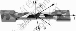
Fig.1 XRD measurement directions
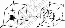
Fig.2 Base of crystal cell and its orthonormal system
So the passage matrix M from the orthonormal reference associated with crystal reference to the sample reference can be found by respective coordinates. This matrix M is useful to determine the position (φ, ψ) of any (hi, ki, li) plan in sample reference.
2.2 Strain and stress tensor determinations in grain scale
Based on the assumption of the continuum mechanics[7-8], in the othonormal reference associated with crystal reference, the distance of a crystal plane
(hi, ki, li) can be introduced:
 (1)
(1)
Thus, the metric tensor gij is reduced before and after deformation of crystal.
In this case, the strain tensor can be written:
 (2)
(2)
where  and gij are the metric tensors of the coordinate system before and after the deformation. Eij is GREEN’s strain tensor and eij is ALMANSI’s strain tensor.
If the elastic constants of the single crystal are known, the application of the HOOK’s law leads directly to the stress tensor in the orthonormal basis associated with the crystal reference.
σcryst=c?εcryst (3)
In general, the stress tensor is interested in the sample reference. Transformation of the stress tensor into the sample reference is done by the matrix M. M is the passage matrix from the orthonormal reference associated with the crystalline reference to the sample reference.
σsample=M-1?σcryst?M (4)
As in all the diffraction methods, it is difficult to know the reference state (stress free lattice parameters) which will be necessary to calculate the stress. However, the penetration depth of XRD in our study is in the same order as Zn film. It is supposed that the stress in the normal direction to the sample surface is supposed to be zero (σ33=0)[9-11].
The experimental error can be estimated by the measurement of elastic strain for the same crystallographic plan with different geometries. The difference between measurements reflects the experimentation error.
3 Experimental
3.1 Materials
Four adjoining Zn coarse grains on the steel substrate are investigated(Fig.3). According to the microanalysis of the SEB (scanning electronic microscopy), Fe and Cu elements were found in this coating and the coating’s thickness is about 10 mm (Fig.4(a)). The coating’s hardness is 60HV under 10 N. The microstructures and an example of one grain are shown in Fig.4(b).

Fig.3 Four Zn grains in steel substrate
3.2 XRD conditions
The experiment is accomplished on a Philips X’Pert 4-circles goniometer. The anticathode used is copper with the wavelength λ(Kα) 0.154 nm. The group planes (0 0 6) (1 0 4) (1 0 1) (2 0 3) (1 0 5) (1 1 4) (2 1 0) (2 1 1) (2 0 4) (2 1 2) are chosen for peak acquisition and stress calculation. The scanning step is 0.002? for 2θ with 2 s per step of the counting time.
3.3 Orientations of 4 different grains
The orientations of the (0 0 6) plan for 4 different grains obtained by scanning the pole figure of this plane are observed. It is obtained by the pole figure by the plan (0 0 6) scanning (Table 1).

Fig.4 Microstructure observation by SEB: (a) Cross section of Zn coating; (b) Zn grain morphology
Table 1 Four grain orientations

3.4 Optimization of couple angle (φ, ψ) and 2θ scanning
For the XRD stress analysis method, obtaining a precise 2θ is very important to calculate the strain and stress. In order to obtain the precise 2θ, it is necessary to optimize the angle (φ, ψ). The key point of optimization of (φ, ψ) is the consecutive scanning around the position φ and then the position ψ with several iterations. The position of φ or ψ is found at the maximum intensity for each scanning. This work can be programmed with the software X-Pert Data Collector. Finally, the spectrum is recorded by the scanning around 2θ and the 2θ value is deduced by software PROFIT PHILIPS with Pseudo-VOIGT function approximation.
3.5 Tensile loading
The loading value is obtained with a strain gauge and a compressible sensor. The macroscopic of the load-strain relationship is shown in Fig.5.
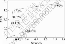
Fig. 5 Loading curve
3.6 Stress calculation
In this experiment, the stiffness tensor of the zinc used is: E1111=165 GPa, E2222=165 GPa, E3333=61.8 GPa, E1212=33.5 GPa, E2323=19.8 GPa, E3131=19.8 GPa, E1122=31.1 GPa, E2233=50 GPa, E3311=50 GPa. The stress is calculated by the measurement of at least 24 planes. Under the experimental conditions, the obtained error of the calculated stress is less than 50 MPa.
4 Results and Discussions
Under the tensile loading (Fig.3), the Schmid factors for the 3 slip directions on the basal plane are calculated for 4 studied grains (Table 2 and Fig.6). It is found that the SCHMID factors for each grain are quite comparable to the 3 slip planes.
Table 2 Schmid factors of different slip directions in basal slip plan (0 0 1)
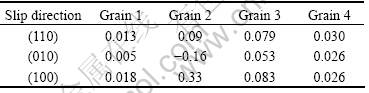

Fig.6 Basal slip system and different slip directions
Figs.7 and 8 show the stress evolution in the loading direction and transverse direction for the four considered grains during loading. In the initial state, the residual stresses are compressive in four grains and their stress distributions are different in each grain and also in the two considered directions. This means that there is heterogeneous distribution of the compressive residual stresses in grain scale in zinc film before tensile loading.

Fig.7 Stress σ11 evolution in loading direction during tensile loading
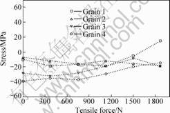
Fig.8 Stress σ22 evolution in transverse direction during tensile loading
During tensile loading in the loading direction, the compressive stress evolves differently in four grains. In grains 2, 3 and 4, the compressive stress increases slightly at the beginning of the exterior tensile loading effect. But in grain 1 with least SCHMID factor, for example, 0.005 in the slip plan (0 1 0), the compressive stress decreases and becomes the tensile stress at the deformation of 0.12%(1 128 N tensile loading). Along with the loading, the compressive stresses are completely relaxed in all grains after the deformation of 0.11%(751 N tensile loading). The interior stresses become tensile at the deformation of 0.15%, but they decrease at the deformation of 1.62%(1 870 N tensile loading). This can be explained that a slip system has occurred inside all grains. It is observed that the tensile stresses arrive at the same values in grains 1 and 4. In transverse direction, the compressive stresses increase firstly without grain 4. In grains 1 and 3, the compressive stresses begin to relax at the deformation of 0.11%, but in contrast in grains 2 and 4. At the deformation of 1.62%, the stress becomes tensile in grain 1, but the compressive stresses reincrease in grains 2 and 3.
5 Conclusions
A new method for strain and stress analysis by XRD in single crystal was developed. The advantage of this method is that it can be applied to both single and multi-crystal material with any crystalline system. This method, once developed, was applied to a galvanized film with coarse Zn grains. Firstly, the residual strain and stresses inside the grains were evaluated for Zn multicrystal film without exterior loading and then four adjoining grains were studied during tensile loading. The determined stresses in the four grains show a significant heterogeneous distribution before and after tensile loading. The experimental results show that the developed method can be used to study single or multicrystal strain and stress analysis in hexagonal system materials. In order to show the validity of the method, more applications should be carried out for more complicated crystalline systems. Errors should also be estimated with more theoretical considerations. To relate the microstructure evolution, the peak width should also be exploited.
References
[1] PARISOT R, FOREST S, PINEAU A. Deformation and damage mechanisms of zinc coatings on hot-dip galvanized steel sheets[J]. Metallurgical and Materials Transactions, 2004, 35A: 797-823.
[2] Karduck p, WIRTH T, PRIES H. Characterization of intermediate layers in hot-dip zinc coated steels[J]. J Anal Chem, 1997, 358: 135-140.
[3] ASARO R, RICE J. Strain localization in ductile single crystals[J]. J Mech Phys Solids, 1977, 25: 309-338.
[4] SAERENS A, VAN HOUTTE P, MEERT B, OUAEVHAEGENS C. Assessment of different X-ray stress measuring techniques for thin titanium nitride coatings[J]. J Appl Cryst, 2000, 33: 312-322.
[5] WELZEL U, LIGOT J, LAMPARTER P, VERMEULEN A. Stress analysis of polycrystalline thin films and surface regions by X-ray diffraction[J]. J Appl Cryst, 2005, 38: 1-29.
[6] ZOTOV N, PETROV K. analysis of the dependence of lattice deformations in CuII-CoII hydroxide nitrate solid solutions on their composition[J]. J Appl Cryst, 1991, 24: 227-231.
[7] FUNG Y C. Foundation of solid mechanics[J]. New Jersey: Prentice-Hall INC, 1965: 89-95.
[8] ORTNER B. On the selection of measurement directions in second-rank tensor (e.g. elastic strain) determination of single crystals[J]. J Appl Cryst, 1989, 22: 216-221.
[9] M’CIRDI L, LEBRUN J-L, INAL K, BARBIER G. Experimental approach of a crystallographic cleavage criterion in a cast aged duplex stainless steel[J]. Acta Mater, 2001, 49: 3879-3887.
[10] WIEDER T. On the strain-free lattice constants in residual stress evaluation by diffraction[J]. Journal of Structural Geology, 2000, 22: 1601-1607.
[11] FRANCOIS M, FERREIRA C, GUILLEN R. Approximate analytical formulae to evaluate the uncertainty in X-ray stress analysis[J]. Materials Science Forum, 2005, 490-491: 124-124.
(Edited by CHEN Can-hua)
Corresponding author: HUANG Wen-jun; Tel: +33-1-44246422; E-mail: hwjpatrice@caramail.com

