 Corrosion behavior of pure aluminum in FeCl3 solution
QU Jun-e(屈钧娥)1, GUO Xing-peng(郭兴蓬)2, WANG Hai-ren(王海人)1, HUANG Jin-ying(黄金营)3
1. School of Chemistry and Material Science, Hubei University, Wuhan 430062, China;
2. Department of Chemistry, Huazhong University of Science and Technology, Wuhan 430074, China;
3. Postdoctoral Station of Technical Institute of Physics and Chemistry, Chinese Academy of Sciences,
Beijing 100101, China
Received 5 January 2006; accepted 22 March 2006
Abstract: The corrosion behavior of pure aluminum in FeCl3 solution was investigated mainly by in-situ AFM (Atomic Force Microscopy). The results of combined researches of AFM, SEM(Scanning Electron Microscopy) and EDAX(Energy Dispersive Analysis of X-ray) show that in addition to uniform attack, pitting corrosion takes place also on pure aluminum surface in FeCl3 solution at open-circuit potential, and impurity elements Fe and Cu are found enriched in corrosion product. In-situ AFM was also used to examine the initiation and development of pitting corrosion of pure aluminum induced by potentiodynamic sweep, and the repassivation of an active pit is observed. AFM tip scratching technique was used to produce a physical defect on metal surface, which is traced by in-situ AFM and it is found that the defect is likely to be preferentially attacked and evolve to pitting corrosion.
Key words: pure aluminum; pitting corrosion; FeCl3 solution; AFM; uniform attack
1 Introduction
Some in-situ imaging technologies such as video camera[1,2] and CLSM (confocal laser scanning microscopy)[3] have been used in corrosion studies, but the detailed morphological characteristics of surfaces can not be obtained from these methods because they have limited resolutions and are restricted to two-dimensional (2D) imaging. The development of STM (scanning tunnel microscopy) and AFM (atomic force microscopy) in recent years makes it possible to provide high resolution 3D images of a sample immersed in an electrolyte solution under open-circuit condition or under electrochemical controls to enhance our understanding of corrosion mechanism. Because the substrate for STM technique must have a relatively high electrical conductivity, for those self-passiviation metals covered with semiconductive protective films, AFM is the more suitable choice for corrosion studies.
Aluminum and aluminum alloys are popular nonferrous metals in industrial application. Protective oxide films are formed spontaneously on their surfaces under air condition, which makes the metal base more resistive to corrosion. However aluminum and its alloys are susceptible to pitting corrosion in chloride environments owing to the breakdown of the oxide layers. There were some reports on pitting corrosion[4-7] of aluminum alloys induced by intermetallic inclusions in neutral or acidic solution, but few studies were involved with corrosion, especially pitting corrosion of pure aluminum using in-situ AFM technology.
Owing to the oxidation ability of Fe3+, FeCl3 is often used as an accelerant to examine the resistance of metal to pitting corrosion. In this work, 0.01 mol/L FeCl3 solution is chosen as corrosive electrolyte, and in-situ AFM is used to investigate the corrosion behavior of 99.9% pure aluminum in FeCl3 solution. The emphases are focused on pitting corrosion behavior of sample induced respectively by electrochemical polarization and by mechanical destroy of metal surface caused by AFM tip scratching.
2 Experimental
The specimens were cut from pure aluminum foil (99.9%) and were electrochemically polished in a solution containing 75% phosphoric acid, 10% glycerol and 15% distilled water at a current density of 0.2 A/cm2 for 4-5 min at 50 ℃. The obtained mirror-like surfaces were etched in 10% NaOH solution for 10 s, rinsed in distilled water and ethanol, dried and stored in air. The corrosive electrolyte was 0.01 mol/L FeCl3 prepared with distilled water.
The experiments were performed in solution at room temperature with a commercial AFM (SPA400) using Si tips in contact mode. The spring constant of the cantilever is 3 N/m. The imaging progress was performed with a loading force of 1 nN on the tip, and tip scratching process was performed with a loading force of 800 nN. The experiments under open-circuit conditions were performed in an open cell with a volume of 1.5 mL. On the bottom of the cell, the specimen was pasted. The topographical images of the sample surface at different immersion time were traced by AFM. The specimen for electrochemical AFM experiment was placed in special electrochemical cell with a silicone rubber O-ring compressed between the cell and the sample surface. The reference electrode and counter electrode were two Pt wires mounted in the cell with a volume of about 0.7 mL, and insulating tapes were used to seal the aluminum surfaces to exposure a small electrode surface area of 0.01 cm2 to avoid great changes of the electrolyte concentrations during the polarization course. Video images of exposed aluminum surface with a magnification of 150 were obtained through an optical microscope and a CCD camera, then were displayed on the computer screen, to make it convenient to move the AFM tip to the regions of our interest for AFM imaging.
3 Results and discussion
3.1 Corrosion at open-circuit potential
The oxide films formed on aluminum surfaces are slightly soluble in pH value range of 4-9 and are thought to be stable in this pH range. Beyond this range, the oxide films may be chemically dissolved, and the metal base will undergo uniform corrosion[8]. In the case of FeCl3, Fe3+ is hydrolyzed to form Fe(OH)3 so that the solution becomes acidic. The pH value of 0.01 mol/L FeCl3 in this work is measured as 2.30 by a pH sensor, which is within the unstable pH region for aluminum. In-situ AFM images of the non-pitting surface of aluminum in 0.01 mol/L FeCl3 measured at the begin- ing (1 min) and 1, 4, 24 h immersion time are shown in Figs.1(a)-(d), respectively.
Fig.1(a) shows the shapes of small convex features as described by WU et al[9] for electrochemical polished aluminum surface. The hills have a size of 200-400 nm in width and 5-10 nm in height. After 1 h immersion,

Fig.1 AFM images of non-pitting surface of aluminum surface in 0.01 mol/L FeCl3 solution at different immersion time: (a) 1 min; (b) 1 h; (c) 4h; (d) 24 h
there are some particle deposits presented on the surface as shown in Fig.1(b), and the roughness of the surface increases. The changes illustrate that aluminum surface suffers general corrosion led by the chemical dissolution of aluminum oxide film. The particles on the surfaces results from the redeposition of corrosion product[5]. It is demonstrated from Figs.1(b) and (c) that the redeposited particles on surface increase with increasing immersion time. After 24 h immersion, the surfaces show a covering film of corrosion product with net-like feature as shown in Fig.1(d).
After 24 h immersion the sample is taken out from the cell, rinsed with distilled water, and dried at room temperature. Then the ex-situ micrographs of the sample are measured by SEM as shown in Fig.2. In Fig.2(a), some pits are observed in a dynamic range from several microns to tens of microns, showing that in addition to uniform dissolution, the aluminum surface suffers form pitting corrosion also. The magnified morphology of the marked region in Fig.2(a) is shown in Fig.2(b). From the image it can be distinguished that there are still some particles of corrosion product near the pits which are not removed by rinsing process. The element EDAX analysis of these particles is performed and Al, O, Cl, Fe and Cu elements are detected in the particles as shown in Fig.2(c).
The purity of the sample is 99.9%, and there are still 0.1% impurities which may influence the corrosion behavior. Cu and Fe are common impurities in pure aluminum, so Cu in corrosion product comes from impurities. But there are two possible origins for Fe element, that is, impurities and Fe ions in electrolyte. Accompanied with the anodic dissolution of aluminum, both H+ and Fe3+ can be reduced to form H2 and Fe2+ respectively to provide cathodic electrochemical current. But Fe2+ ions are voluntary to be oxidized to Fe3+ ions by oxygen in the aerated solution. So the particles of corrosion product might be complex compounds comprising hydrates of Al(OH)3, Fe(OH)3, Al(OH)xCl3-x, Fe(OH)xCl3-x, CuCl2 etc.
3.2 Electrochemically induced pitting corrosion
After fixing the aluminum foil sample, introducing 0.01 mol/L FeCl3 solution by micro-injector to the ECAFM cell and finishing connection between the electrodes and potentiostat, potentiodynamic polarization sweep is performed from the open-circuit potential (OCP) to +500 mV relative to OCP at a scan rate of 10 mV/s. From the video images, uprising of hydrogen bubbles from the surface is observed accompanied with pitting corrosion during the polarization. After polarization, a small part of solution is fetched out and reinjected into the cell again to stir the solution slightly to drive the hydrogen bubble away from the surface, then the AFM
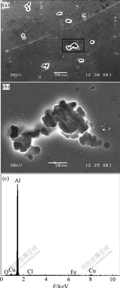
Fig.2 SEM micrographs ((b) is magnified micrograph of marked region in (a) of aluminum surface obtained after 24 h immersion in 0.01 mol/L FeCl3 solution) and EDAX analysis(c) of corrosion product particles
tip is moved to the pitting areas to get detailed topographies. Three pits are chosen to be traced. AFM images of pit 1 and pit 2 are measured as shown in Fig.3(a), and pit 3 in Fig.4(a). To check the effect of imaging scan on the pits, the images of the three pits obtained after a second imaging scan are shown in Fig.3(b) and Fig.4(b). Then another potentiodynamic polarization sweep is performed from OCP to +300 mV relative to OCP at a scan rate of 15 mV/s. After the second polarization course, the detailed AFM images of the three pits are measured again after hydrogen bubble is driven away as shown in Fig.3(c) and Fig.4(c).
The sectional profile along the line in Fig.3(a) is presented in Fig.5, form which we can read the pit depth and orifice diameter. The depths and orifice diameters of pit 1 and pit 2 in Fig.3(a), Fig.3(b) and Fig.3(c) measured along the same line position are recorded, as shown in Table 1. Similarly, the depth and orifice diameter of pit 3 measured at the position along the line as shown in Fig.4(a) are recorded, which are also presented in Table 1.
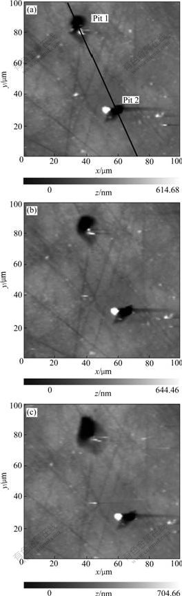
Fig.3 AFM images of pit 1 and pit 2: (a) First imaging scan after first polarization; (b) Second imaging scan after first polarization; (c) Imaging scan after second polarization
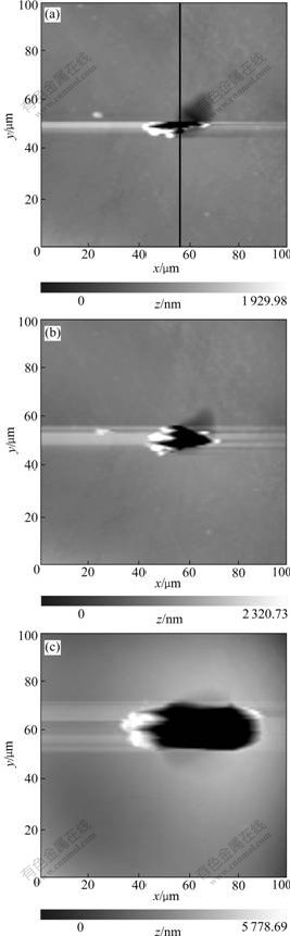
Fig.4 AFM images of pit 3: (a) First imaging scan after first polarization; (b) Second imaging scan after first polarization; (c) Imaging scan after second polarization
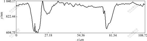
Fig.5 Sectional profile for pit 1 and pit 2 in Fig.3(a)
Table 1 shows that the second AFM imaging scan of pit 1 and pit 2 does not lead to obvious changes (Figs.3(a) and (b)) of pit size. But for pit 3 the second imaging scan enlarges the pit size both in lateral and vertical direction (Figs.4(a) and (b)). This enlargement should be ascribed to the removal of corrosion produce covered on the pit or/and the removal of oxide layers loosely bound to the surface. The removal behavior can not only directly lead to the enlangment of pit size, but also expose the aluminum base to solution to enhance pitting corrosion.
Table 1 Depth and orifice diameter for pits in Fig.3 and Fig.4
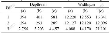
The quantitative profile analysis in Table 1 demonstrates that from Fig.3(b) to Fig.3(c) the depth and the diameter of pit 1 increase, but a little change of size takes place on pit 2. This is in good agreement with the observation of CCD that during the second polarization, uprising of hydrogen bubbles is observed from the region around pit 1 but not pit 2, meaning that pit 1 which is initiated in the first polarization sweep loses activity and is repassivated in the second polarization sweep. The radius of pit 2 is about 3.5 μm, which is between the radius range of 0.1-6.0 μm for metastable pit described in the research of PRIDE et al[10]. However because from the CCD viedo it is hard to decide whether the active period for pit 1 is in agreement with the accepted life-span of mestable pit (often within several second [11]), there is still another possibility that pit 2 is not a metastable pit and just dies in the second polarization scan owing to the change of corrosion enviorment caused by solution-stirring.
From the changes taken place on pit 1 and pit 3 as shown in Fig.3, Fig.4 and Table 1, we can get the conclusion that pit 3 develops more rapidly in the lateral and vertical direction than pit 1. It is demonstrated that different pitting regions reveal dissimilar activity for pitting corrosion owing to the difference of local physical and electrochemical characterizations. Otherwise the diffierent shapes of pits might be a possible reason for their diffierent developing speed. Pit 3 is a partially-occluded pit covered with corrosion product or oxide layer, and pit 1 is an open one. For the pit 1, the intercommunion among electrocytes within the pit and in the bulk solution is much easier so that the high pH value necessary for autocatalytic pit propagation [12] is relatively difficult to maintain, accordingly its development is tempered compared with pit 3.
3.3 Pitting corrosion induced by AFM tip scratching
It is reported that the AFM tip-surface interaction in corrosive medium can enhance the dissolution rate of metal surface and produce cavities in the scratched areas [13-15]. In this work, AFM tip scratching techniques was used to create an artificial physical defect on the surface of aluminum foil and the topographic changes on the defect region with evolution of immersion time in 0.01 mol/L FeCl3 were recorded by in-situ AFM.
The surface morphology of a pure aluminum (99.9%) scratched by AFM tip in 0.01 mol/L FeCl3 solution is shown in Fig.6(a). The square 20 μm×20 ?m central area is scratched by the tip with a loading of 800 nN for 30 min at a scan frequency of 8 Hz to form an impression. The friction forces between the tip and the sample cause local heating of the substrate, which provides enough energy to overcome the activation barrier for the chemical reaction of chloride anions with metal ions. Meanwhile the tip scratching causes mechanical destroy of the metal surface, as the overall result, the dissolution of the substrate is accelerated[15].
The topographical images measured at the fabricated impression region after 1 h and 6 h immersion in FeCl3 solution are measured, as shown in Fig.6(b) and
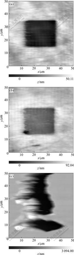
Fig.6 Topographies of artificial impression formed by AFM tip scratching(a) and measured after 1 h(b) and 6 h(c) immersion in 0.01 mol/L FeCl3
Fig.6(c). After 1 h immersion a new small pit with depth of about 20 nm appears in the bottom left corner of the impression. After 6 h, the scratching formed impression cannot be distinguished and two pits with depth of about 30 μm are observed in this region. The results illustrate that pitting corrosion tends to originate from the scratched area.
Supposing that the contact area between the tip and the surface during the scratching process is equal to the hemispherical area of a radius tip(approximate 20 nm), the intensity of exerted pressure on surface is calculated as 3.17×10⁸ Pa. On one hand the strong interaction between the tip and the surface might destroy the protective films (including corrosion product film and oxide film), on the other hand the metal base at scratched position becomes mechanically stressed and physically different from the around region. So the electrochemical activity of scratched region is relatively high and likely to be preferentially attacked in the environment containing chloride ions to develop to pitting corrosion.
In the first 30 min-scratching course to produce the impression in Fig.6(a), the surface of the scratched aluminum has repassivation ability. As a result of the process of surface depassivation caused by the AFM tip scratching, followed by limited dissolution, redeposition of corrosion product and repassivation, the enhanced dissolution is uniform, and a smooth impression with a flat bottom is formed. This is essential erosion corrosion [13]. But after a period of immersion in FeCl3 solution, the scratched region is preferentially attacked by Cl-1 ions and its activity is enhanced. In this case active dissolution overwhelmes repassiviation, and the high reactivity of bare aluminum ensures rapid localized attack, so self-catalyzed pit corrosion happens and develops with evolution time. Because physical and electrochemical characteristics are most discrepant in the intersection regions between the scratched area and unscratched area, we can find from Fig.6(b) that pit corrosion is originated firstly from the intersection corner, which strongly proves that physical defects have high activity for pitting corrosion.
4 Conclusions
1) The comprehensive researches by AFM, SEM show that 99.9% aluminum sample suffers from general corrosion and pit corrosion in FeCl3 solution. The redeposition particles of corrosion product are examined by EDAX to be complex compounds possibly comprising hydrates of Al(OH)3, Fe(OH)3, Al(OH)xCl3-x, Fe(OH)xCl3-x, CuCl2, etc.
2) By in-suit electrochemical AFM studies, the initiation, propagation and repassivation of pitting corrosion of pure aluminum in FeCl3 solution under electrochemical controls are successfully observed. Owing to the diversity of physical and electrochemical characterizations, different pitting regions reveal different activities for pitting corrosion under the same polarization condictions.
3) AFM tip scratching technique is used to form an artificial defect on aluminum surface under open-circuit condition in FeCl3 solution. The in-situ AFM observation of pitting corrosion originated from the artificial impression demonstrates that the physical defects on metal surface have high activity for pitting corrosion, and are likely to be attacked preferentially to pitting corrosion.
References
[1] SEHGAL A, LU D, FRANKEL G S. Pitting in aluminum thin films [J]. J Electrochem Soc, 1998, 145(8): 2834-2840.
[2] FRANKEL G S. The growth of 2-D pits in thin film aluminum [J]. Corros Sci, 1990, 30: 1203-1217.
[3] MAHER A A, WILLIAM H S. Detection of localized corrosion of aluminum alloys using flourescence microscopy [J]. J Electrochem Soc, 1998, 145(5): 1571-1577.
[4] RYNDERS R M, PAIK C H, KE R. Use of in-situ atomic force microscopy to image corrosion at inclusions [J]. J Electrochem Soc, 1994, 141(6): 1439-1445.
[5] KOWAL K, DEUCCIA J, JOSEFOWICZ J Y, LAIRD C, FARRINGTON G C. In situ atomic force microscopy observations of the corrosion behavior of aluminum-copper alloys [J]. J Electrochem Soc, 1996, 143(8): 2471-2491.
[6] LEBLANC P, FRANKEL G S. A study of corrosion and pitting initiation of AA2024-T3 using atomic force microscopy [J]. J Electrochem Soc, 2002, 149(6): B239-B247.
[7] WARNER T J, SCHMIDT M P, SOMMER F, BELLOT D. Characterization of corrosion initiation on 2024 aluminum alloy by atomic force microscopy [J]. Z Metallkd, 1995, 86(7): 494-501.
[8] AMBAT R, DWARAKADASA E S. Studies on the influence of chloride ion and pH on the electrochemical behavior of aluminum alloys 8090 and 2014 [J]. Journal of Applied Electrochemistry, 1994, 24: 911-916.
[9] WU Hui-qiang, ZHANG Xiao, HERERT K R. Atomic force microscopy study of the initiate stage of anodic oxidation of aluminum in phosphoric acid solution [J]. J Electrochem Soc, 2000, 147(6): 2126-2132.
[10] PRIDE S T, SCULLY J R, HUDSON J L, Metastable pitting of alnminum and criteria for the transition to stable pit growth [J]. J Electrochem Soc, 1994, 141(11): 3028-3039.
[11] SZKLARSKA-SMIALOWSKA Z. Pitting corrosion of aluminum [J]. Corros Sci, 1999, 41(9): 1743-1767.
[12] HOAR T P. Electrode Processes [M]. London: Butter-Worths, 1961.
[13] CHEN L, GUAY D. Selected dissolution of aluminum initiated by atomic force microscopy tip-surface interaction [J]. J Electrochem Soc, 1994, 141: L43-L45.
[14] SCHMUTZ P, FRANKEL G S. Influence of dichromate ions on corrosion of pure aluminum and AA2024-T3 in NaCl solution studied by AFM scratching [J]. J Electrochem Soc, 1999, 146: 4461-4472.
[15] QU Jun-e, GUO Xing-peng. Investigation on the accelerated dissolution of metal induced by AFM tip scratching and suppressed by inhibitors [J]. Electrochemistry, 2005, 11(3): 319-323. (in Chinese)
(Edited by YANG Bing)
Corresponding author: QU Jue-e; Tel: +86-27-50865297; E-mail: ccjequ@sohu.com

