���÷�ĩұ�����Ʊ��Ŀ������ɢ�ѻ� ���ϲ��ϵı�����ĥ������
��Դ�ڿ����й���ɫ����ѧ��(Ӣ�İ�)2014���5��
�������ߣ�D. P. MONDAL J. D. MAJUMDAR M. D. GOEL G. GUPTA
����ҳ�룺1379 - 1386
�ؼ��ʣ��ѻ����ϲ��ϣ��սĥ�����ܣ���ʴ������֯
Key words��Ti matrix composite; sintering; wear property; corrosion; microstructure
ժ Ҫ�����÷�ĩұ�����Ʊ��������ɢ���ѻ����ϲ��ϣ�������ĥ���ʴ��Ϊ�����о���������������Ʊ��ĸ��ϲ�����֯���ڦ�-Ti�����з�ɢ��ƽ����Ϊ50~150 ��m�Ŀ����顣���ϲ��ϵĶ���Թ�����ѹ�ƹ������غɶԿ�����������ƻ��������鱾���Ŀ������ԡ�X������������������ϲ�����Al2O3��SiO2��TiO2�ͦ�-Ti����ɡ������ѺϽ����Ӳ��ΪHV 240�������ϲ��ϵ���Ӳ����HV 1100~HV 1800��Χ�ڱ仯��ĥ��ʵ����������������Ti-6Al-4V�Ͻ𣬸��ϲ��϶�Ӳ�������WC��Ŀ�ĥ�����ܵõ�������ǿ�����ϲ�����3.56%NaCl(��������)��Һ�еĸ�ʴ��Ϊ���������͵�ʴ���ܸ��ƣ���ʴ��λ����(����)�����ƶ���Ȼ����������Ti-6Al-4V�Ͻ���ȣ��������ɢ�ѺϽ�ĸ�ʴ��������
Abstract: The cenosphere dispersed Ti matrix composite was fabricated by powder metallurgy route, and its wear and corrosion behaviors were investigated. The results show that the microstructure of the fabricated composite consists of dispersion of hollow cenosphere particles in ��-Ti matrix. The average pore diameter varies from 50 to 150 ��m. The presence of porosities is attributed to the damage of cenosphere particles due to the application of load during compaction as well as to the hollow nature of cenospheres. A detailed X-ray diffraction profile of the composites shows the presence of Al2O3, SiO2, TiO2 and ��-Ti. The average microhardness of the composite (matrix) varies from HV 1100 to HV 1800 as compared with HV 240 of the as-received substrate. Wear studies show a significant enhancement in wear resistance against hardened steel ball and WC ball compared with that of commercially available Ti-6Al-4V alloy. The wear mechanism was established and presented in detail. The corrosion behavior of the composites in 3.56% NaCl (mass fraction) solution shows that corrosion potential (��corr) shifts towards nobler direction with improvement in pitting corrosion resistance. However, corrosion rate of the cenosphere dispersed Ti matrix composite increases compared with that of the commercially available Ti-6Al-4V alloy.
Trans. Nonferrous Met. Soc. China 24(2014) 1379-1386
D. P. MONDAL1, J. D. MAJUMDAR2, M. D. GOEL1, G. GUPTA1
1. CSIR-Advanced Materials and Processes Research Institute, Bhopal 462 064, India;
2. Department of Metallurgical and Materials Engineering, Indian Institute of Technology, Kharagpur 721 302, India
Received 29 July 2013; accepted 8 October 2013
Abstract: The cenosphere dispersed Ti matrix composite was fabricated by powder metallurgy route, and its wear and corrosion behaviors were investigated. The results show that the microstructure of the fabricated composite consists of dispersion of hollow cenosphere particles in ��-Ti matrix. The average pore diameter varies from 50 to 150 ��m. The presence of porosities is attributed to the damage of cenosphere particles due to the application of load during compaction as well as to the hollow nature of cenospheres. A detailed X-ray diffraction profile of the composites shows the presence of Al2O3, SiO2, TiO2 and ��-Ti. The average microhardness of the composite (matrix) varies from HV 1100 to HV 1800 as compared with HV 240 of the as-received substrate. Wear studies show a significant enhancement in wear resistance against hardened steel ball and WC ball compared with that of commercially available Ti-6Al-4V alloy. The wear mechanism was established and presented in detail. The corrosion behavior of the composites in 3.56% NaCl (mass fraction) solution shows that corrosion potential (��corr) shifts towards nobler direction with improvement in pitting corrosion resistance. However, corrosion rate of the cenosphere dispersed Ti matrix composite increases compared with that of the commercially available Ti-6Al-4V alloy.
Key words: Ti matrix composite; sintering; wear property; corrosion; microstructure
1 Introduction
Titanium and its alloys are widely used for dental and orthopedic implants due to their excellent chemical stability, good mechanical and biocompatibility properties [1]. In this regard, it is relevant to mention that porous Ti-6Al-4V alloy is a future bio-material as it can provide not only a favorable environment for bone ingrowth, but also similar elastic modulus and stiffness to those of the surrounding bone, which would be expected to reduce the extent of stress shielding [2-3]. In the past, porous titanium was reported to be developed by powder metallurgy route [4], space holder method [5], rapid prototyping method [6], and the replication of polymeric sponge [7]. However, a precise control of pore structure (e.g., porosity, pore size, pore shape, interconnection between pores, and pore alignment) for the achievement of improved mechanical properties and biological performance is a real challenge [8]. Furthermore, porous titanium has poor friction and wear properties. Although these properties can be improved by using particulate reinforced composites, the weak interface between the particles and matrix often results in debinding or loosening of the particles. In the wear process, the release of these hard particles can cause further damage to the implant and a cascade of cellular activity that degenerates bone.
Among the reinforcements used for synthesizing MMCs, hollow fly ash particulate (cenospheres) has recently gained a significant attraction due to its excellent energy absorption properties [9]. Considerable studies have been conducted on measuring the mechanical properties of metal matrix syntactic foams [10-13] and coefficient of thermal expansion of aluminum based composites [14]. It has been observed that hollow spherical cenosphere particles in aluminum matrix provide excellent wear resistance in both dry and lubricating conditions [15]. Because of spherical nature of these particles, these particles may not cause wear to the counter surface or the implant. In the past, the development of cenosphere dispersed titanium foam was presented by powder metallurgy route with an average porosity of 45%-70% and elastic modulus of 25-42 GPa by the present authors [16].
In this work, the wear and corrosion behavior of the cenosphere dispersed titanium matrix composite was studied in detail and compared with those of the commercially available Ti-6Al-4V alloy.
2 Experimental
Sintering of cenosphere dispersed Ti-based composite was performed by blending of cenosphere (12%) with particle size of 75-150 ��m and Ti with particle size of 20-40 mm for 7 h. The cenospheres primarily contain mullite and sementite. The chemical composition (mass fraction) of cenospheres is as follows: 28.5% Al2O3, 58.3% SiO2, 6.3% Fe2O3, 0.4% TiO2, and 5.8% C(carbon) [17]. The XRD pattern was reported in detail elsewhere [17]. The compaction of the blended cenosphere dispersed Ti was conducted at 75 MPa (this pressure was used to avoid crushing of cenospheres during cold compaction for making pallets) at ambient temperature and at 600 ��C for 2 h (a) and 400 ��C for 2 h followed by heat treatment at 800 ��C for 2 h (b). After debinding (removal of the binding agent used during cold compaction through heating), sintering of the compact was conducted at 1200 ��C under vacuum sealed condition for 3 h. Following sintering, the microstructures of the sintered samples (both the top surface, i.e., the surface exposed directly to the atmosphere which was removed through polishing and then used for microstructural characterization and XRD analysis) were characterized by optical microscopy and scanning electron microscopy (SEM). Any reaction did not take place between Ti and Si cenospheres, which was confirmed by the XRD analysis. If any reaction takes place between Ti and Si, there will be the presence of the peak corresponding to Ti5Si3 phase. Furthermore, the cenospheres did not melt during sintering process. The top surface here means the inner top surface (about 2 mm inside from the bare top surface). Thus, the XRD pattern of this surface indicates the XRD pattern of inner materials. The XRD pattern did not show any peaks for Ti-Si intermetallics as visible from XRD analysis. The pallets are small and Ti matrix has good thermal conductivity. It is therefore expected that the samples are uniformly heated during debinding and sintering. Conditionally, the samples are porous. Thus, there will be no difference in microstructure and phase constituents at different locations of sintered pallets. A detailed analysis of the phases was carried out by X-ray diffraction technique.
The compositions of the top surface and cross section of the composite were measured by energy dispersive spectroscopy (EDS) analysis attached to the SEM. The microhardness of the surface was measured by Vickers microhardness tester using a 100 g (0.98 N) applied load. Finally, the kinetics of wear of the treated surface was compared with that of the as-received one by a fretting wear tester (DUCOM, TR-283M-M4). Before the test, all samples were mechanically polished to the roughness of 2.5 ��m and cleaned using acetone and dried. Commercial bearing AISI E-52100 grade steel ball with the hardness of HRC 58-66 and the diameter of 5 mm and WC ball with the diameter of 5 mm were used as counter body. The wear tests were carried out at varying normal loads of 5 and 10 N for constant testing duration of 30 min and at constant frequency of 10 Hz and constant stroke length of 1 mm. With the help of Winducom 2006 software the cumulating loss of depth with time was computed. The microstructure of the worn debris was analyzed with SEM to understand the wear mechanism. The electrochemical property of the surface in terms of pitting corrosion resistance was compared with that of the conventional Ti-6Al-4V alloy by potentiodynamic anodic polarization study in Hank��s solution with the following electrolytic composition: 0.185 g/L CaCl2, 0.4 g/L KCl, 0.06 g/L KH2PO4, 0.1 g/L MgCl2��6H2O, 0.1 g/L MgSO4��7H2O, 8 g/L NaCl, 0.35 g/L NaHCO3, 0.48 g/L Na2HPO4 and 1.00 g/L D-glucose. In the corrosion study, a standard calomel electrode was used as the reference electrode and platinum was used as the counter electrode [15]. Polarization was carried out from -2 to 7 V (vs SCE) at a scanning rate of 2 mV/s. The pitting corrosion behavior was determined by measuring the primary potential for pit formation, ��pp1 (the potential at which there is a sudden rise in current density with a small increase in potential) and corrosion potential (��corr).
3 Results and discussion
The microstructures and phases present in cenosphere reinforced titanium composite were characterized. A detailed investigation of the mechanical properties of the composite in terms of microhardness and wear resistance was evaluated. Finally, the corrosion resistance property of the cenosphere dispersed titanium composite was evaluated and compared with respect to the Ti-6Al-4V alloy in Hank��s solution.
3.1 Microstructural characterization of cenosphere Ti matrix composite
Figures 1(a) and (b) [16] show SEM images of the cenosphere dispersed Ti matrix composite debinded at 600 ��C for 2 h (a) and 400 ��C for 2 h followed by heat treatment at 800 ��C for 2 h (b) and sintering at 1200 ��C for 3 h, respectively.
Figure 1 shows the presence of globular cenosphere (as shown by arrows) in ��-Ti matrix and the composites are indeed porous in nature. The porosity varies with the process parameters. The specimen debinded at 600 ��C for 2 h possesses a higher area fraction of porosities (70%) than that debinded by two steps (i.e., at 400 ��C for 2 h followed by 800 ��C for 2 h), i.e., 45%. A lower area fraction of porosities is observed when two-step debinding is conducted prior to sintering. This is attributed to the fact that, porosities are also partly generated due to the vaporization of organic binder during sintering and partly due to inadequate bonding between titanium particles. The lower area fraction of porosities when the specimen is debinded for adequate time is attributed to the presence of lower volume fraction of organic binder between the powder particles while sintering and hence, more chances of bonding between the particles appear.
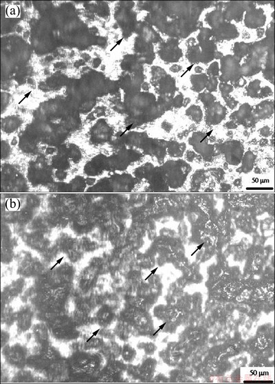
Fig. 1 SEM images of cenosphere dispersed Ti matrix composites debinded at 600 ��C (a) and 400 ��C (b) for 2 h [16]
Figures 2(a)-(c) show the higher magnification view of the top surface (a), the sintered zone (b) (matrix vs cell wall), and the porous region (c) (inside hollow region of cenosphere in foam) of cenosphere dispersed Ti matrix composite debinded at 400 ��C for 2 h followed by heat treatment at 800 ��C for 2 h and sintering at 1200 ��C for 3 h.
From Fig. 2 it may be noted that the pores are of different shapes with size varying from 25 to 200 ��m and distribute uniformly throughout the surface. The porosity formation is due to the presence of hollow cenospheres and its subsequent removal during polishing operation after sintering and also due to the no filled inter-particle spacing during sintering. Further, it can be observed that the solid region is defect free with the presence of titanium grain with an average grain size of 3-6 ��m (Fig. 2(b)). Titanium grains observed in Fig. 2(b) also show the presence of fine particle dispersoids (crushed cenosphere shells). On the other hand, in the porous region, there is cenosphere with a cell thickness of 2.5 ��m (Fig. 2(c)). This figure also shows the inter-particle porosities (as marked with arrow). The interface between the cenosphere and ��-Ti matrix is continuous and defect free. The composition distribution in different regions of Fig. 2(a) is summarized in Table 1.
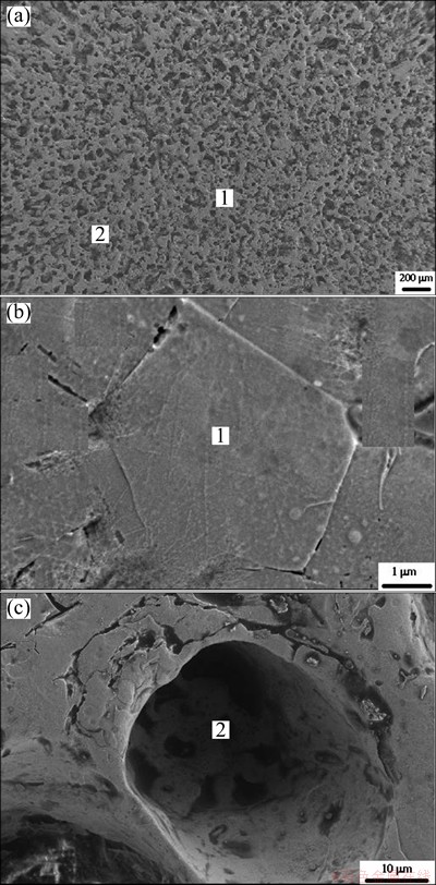
Fig. 2 Higher magnification SEM images of top surface (a), sintered zone (b), and porous region (c) of cenosphere dispersed Ti matrix composite
Table 1 Composition distribution in different zones in Fig. 2
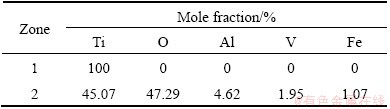
From Table 1, it may be noted that the solid region is enriched predominantly with titanium. On the other hand, in the porous region there are significant amount of Si, Al and O apart from minor amount of Ti. However, EDS analysis confirms that the porous region is cenosphere only. Titanium comes into the porous region in EDX primarily because of the spreading of Ti over cenosphere regions during machining and polishing of metallographic samples.
Figure 3 [16] shows the XRD profile of the top surface of the cenosphere dispersed Ti matrix composite debinded at 400 ��C for 2 h followed by heat treatment at 800 ��C for 2 h and sintering at 1200 ��C for 3 h. The XRD profile shows the presence of ��-Ti, mullite, SiO2and TiO2.
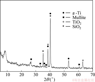
Fig. 3 XRD profile of top surface of cenosphere dispersed Ti matrix composite [16]
3.2 Microhardness of cenosphere Ti matrix composite
The microhardness of Ti matrix region of top surface and cross section of the sintered titanium cenosphere composite was extensively measured. Table 2 summarizes the average microhardness, mechanical and electrochemical properties of the composites under different conditions.
From Table 2, it may be noted that when single step debinding is conducted, the average hardness achieved is HV 1190. When debinding is carried out in two steps, the average microhardness is HV 1350. The improvement in hardness of the cenosphere dispersed Ti matrix composite as compared with that of the commercially available Ti-6Al-4V alloy (HV 240) is attributed to the presence of dispersed fine and fragmented cenosphere particles in matrix, which leads to dispersion strengthening. Higher hardness in two-stage debinding process may be due to greater density and better bonding between Ti particles. Furthermore, strain hardening of the matrix due to high pressure applied during compaction is also significant.
3.3 Fretting wear behavior of cenosphere Ti matrix composite
Figure 4 shows the comparison of the kinetics of wear in terms of the wear depth as a function of time measured by friction and wear monitor (Model TR-208M1) using specimen as disc and hardened steel ball (with diameter of 3 mm) as a pin for commercially available Ti-6Al-4V alloy. The analysis was carried out at an applied load of 10 N and cenosphere dispersed Ti matrix composites debinded at 400 ��C for 2 h followed by sintering at 1200 ��C for 3 h at applied load of 5 N and 10 N, respectively.
From Fig. 4, it is evident that the wear depth increases with the increase of time and attains the steady state wear at later stage for all the samples. It is interesting to note that at the initial stage the wear rate of Ti cenosphere composite is similar to that of Ti-6Al-4V alloy. But at later stage, Ti-6Al-4V alloy shows higher wear depth than Ti cenosphere composite. It is further noted that, under similar conditions, Ti cenosphere composite attains almost constant wear rate after a time of 100 s, but, Ti-6Al-4V alloy attains the steady state wear rate after 1600 s. A close comparison of different curves in Fig. 4 also reveals that the wear resistance of the sintered Ti cenosphere composite sample is about 60% higher than that of dense Ti-6Al-4V alloy. The effect of load evidences a marginal improvement in wear with increase in applied load. The significant improvement in wear resistance of the sintered titanium cenosphere composite is attributed to: 1) improved microhardness of the Ti matrix in the composite, 2) lower area of interaction between mating surface and matrix in the composite, 3) a large fraction of energy during the wear processes lost due to the cushion effect of the cenosphere present on the surface and subsurface region, and 4) lower degree of adhesion due to the presence of cenosphere cells and also due to greater extent of heat conduction because of porous structure [16].
Table 2 Average microhardness, mechanical and electrochemical properties of composite
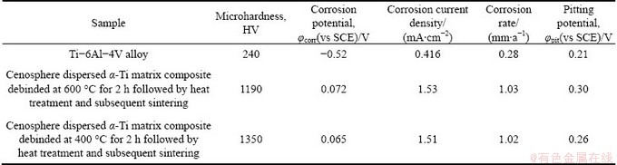
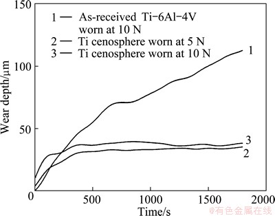
Fig. 4 Kinetics of wear in terms of wear depth as function of time for different samples
Figure 5 shows the variation of coefficient of friction of commercially available Ti-6Al-4V alloy at an applied load of 10 N and cenosphere dispersed Ti matrix composites debinded at 400 ��C for 2 h followed by sintering at 1200 ��C for 3 h at applied load of 5 and 10 N, respectively.
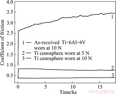
Fig. 5 Variation of coefficient of friction of different samples at different applied loads
From Fig. 5, it is evident that the coefficient of friction increases gradually from 2.6 to 3.5 for commercially available Ti-6Al-4V alloy. In cenosphere dispersed Ti matrix composites, it is constant to a value of 0.4 at an applied load of 10 N and 0.8 at an applied load of 5 N. The increased coefficient of friction in commercially available Ti-6Al-4V alloy is attributed to its low hardness; its gradual increasing trend is due to the surface roughening caused by wearing of the surface with the combined action of abrasive and fretting. Significantly low value of coefficient of friction in case of cenosphere dispersed Ti is mainly due to the presence of cenosphere cell that absorbs shock during fretting motion. A detailed analysis of the worn surface was undertaken to understand the mechanism of wear. Figure 6 shows the microstructures of the worn surface of commercially available Ti-6Al-4V alloy at an applied load of 10 N and cenosphere dispersed Ti matrix composites at applied loads of 5 and 10 N, respectively.
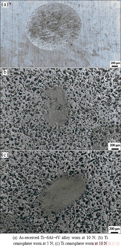
Fig. 6 Microstructures of worn surface at different applied loads
A close comparison between Fig. 6(a) and Fig. 6(b) reveals that the degree of wear in terms of dimension of worn area is much lower in the cenosphere dispersed Ti as compared to the as-received one under the same conditions. Furthermore, on both surfaces there are fine scratches and lose worn debris. The degree and area fraction of worn debris are larger in as-received Ti-6Al-4V alloy surface as compared to those of the composite. Finally, in the as-received Ti-6Al-4V alloy, there is a signature of material flow and material removal in the form of pits attributed to the combined action of adhesive and fretting wear. In cenosphere dispersed Ti matrix composite the surfaces turn smoother following wear, which is due to the collapse of cenosphere cell and its subsequent entrapment within the matrix because of the combined action of load and frictional heating. The collapsed and fragmented fine cenosphere cells get accommodated at the hollow space provided by itself (pores of the composite) and get accumulated. Due to the presence of fragmented hard debris, there is lower kinetics of wear and hence, a reduced degree of scratch. As a consequence, a strong and polished mechanically mixed layer forms in the Ti cenosphere porous composite. In case of dense Ti-6Al-4V alloy, materials remove from the surface either by abrasive or adhesive action continuously released from the wear groove. The presence of fine scratches (as observed in Fig. 7(a)) is attributed to the abrasive action of the mating surface. The microstructure at a high magnification shows the presence of deep scratches, pits and worn debris in Ti-6Al-4V alloy. Figure 7(b) shows the presence of fine scratches with a lower area fraction of loose debris on the surface and the debris get accommodated at the hollow space provided by cenosphere (marked by A). Furthermore, there are also a few micro-cracks that are attributed to: 1) the fracture of the cenosphere cells from the matrix, 2) cracking of the matrix at cenosphere-matrix interface, and 3) debinding of Ti particles in the matrix. At higher magnification the porosities are also visible. However, there is no signature of micro-crack formation from the porosities due to application of load. Figure 7(c) shows the presence of cenosphere particles broken and adhered to the surface after wear for cenosphere dispersed ��-Ti matrix composite. Few pores are also observed on the surface apart from fine scratches. A detailed EDS analysis shows the presence of oxides in the worn debris hence, the distributed particles are primarily oxides of aluminum and silicon due to damage of hollow cenosphere under combined action of load and fretting motion.
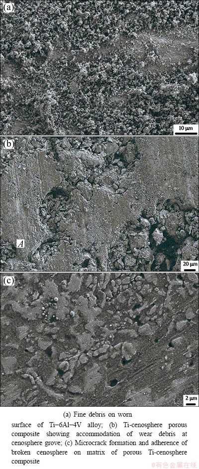
Fig. 7 SEM images of cenosphere Ti matrix composite and Ti-6Al-4V alloy after abrasion test
3.4 Corrosion behavior of cenosphere Ti matrix composite
The corrosion behaviors of the as-received and cenosphere dispersed Ti matrix composite were evaluated by potentiodynamic polarization studies in 3.56% NaCl solution. The corrosion current density (Jcorr) and corrosion potential (��corr) values for the respective samples are obtained from the intersection of cathodic and anodic Tafel plots. The calculated values of corrosion current density (Jcorr), corrosion potential (��corr) and corrosion rate are presented in Table 2. Detailed analysis of the corrosion data reveals that corrosion potential (��corr) shifts significantly towards nobler direction. Shifting of the corrosion potential towards the nobler direction is possibly attributed to the presence of a large fraction of cenosphere, which is cathodic in nature. A comparison of corrosion rate, however, reveals that there is a significant enhancement of corrosion rate in cenosphere dispersed Ti matrix composite as compared to Ti-6Al-4V alloy. The increase in corrosion rate is possibly attributed to the large area fraction of porosities in the microstructure and hence, decreasing in nominal area of Ti exposed to the solution, causing the enhancement of current density. Even though the nominal contact area decreases, because of porosity and the presence of cenosphere, 1) the interfacial area between cenosphere and the Ti particles increases and 2) more curved surface leads to more effective area of Ti exposed to the corrosion media, and thus increases the corrosion current density. Pitting potential also increases in cenosphere dispersed Ti matrix composite as compared to the Ti-6Al-4V alloy. The improvement in pitting corrosion property confirms that pitting corrosion resistance is not deteriorated due to the presence of cenosphere, even though there are pores. A magnified view of the pore is shown in Fig. 2(c). From Fig. 2(c) it is relevant that presence of pores does not really expose the fresh surface, as it is coated with cenosphere cell which is nobler. Furthermore, the interface between the cenosphere and matrix is continuous and defect free. During compaction, part of the cenosphere particles are fragmented and disperse throughout the surface. Cenosphere fragments (complex oxides of silicon and aluminum) increase the overall areas of interface, but do not deteriorate the pitting property. This is attributed to the fact that cenospheres are highly inert to the corrosion solution.
4 Conclusions
1) The surface microstructure of the cenosphere dispersed Ti matrix composite consists of a large area fraction of porosities and dispersion of complex silicate within the matrix. The matrix forms the network.
2) The fragmented fine cenospheres (silicates) in the matrix improve the average microhardness of the matrix from HV 240 to HV 1350.
3) A significant improvement in wear resistance is observed on the surface when it is evaluated by fretting wear testing against both WC and steel ball at applied load of 10 N. The porous composites show plateau wear depth which is attained at very short time.
4) The evaluation of corrosion behavior shows that ��corr shifts towards nobler direction in cenosphere dispersed Ti matrix composite as compared with Ti-6Al-4V alloy. However, the corrosion rate of the composite material increases as compared with commercially available Ti-6Al-4V alloy, possibly due to the presence of porosities and hence, increasing in effective area for corrosion reaction and causing the enhancement in corrosion rate.
Acknowledgement
Financial supports from various funding agencies Tata Steel, Jamshedpur, Department of Science and Technology, New Delhi, Council of Scientific and Industrial Research, New Delhi and Board of Research on Nuclear Science, Bombay for the present study are gratefully acknowledged.
References
[1] LONG M, RACK H J. Titanium alloys in total joint replacement��A materials science perspective [J]. Biomaterials, 1998, 19(18): 1621-1639.
[2] RYAN G, PANDIT A, APATSIDIS D P. Fabrication methods of porous metals for use in orthopedic applications [J]. Biomaterials, 2006, 27(13): 2651-2670.
[3] ST-PIERRE J P, GAUTHIER M, LEFEBVRE L P, TABRIZIAN M. Three-dimensional growth of differentiating MC3T3-E1 pre-osteoblasts on porous titanium scaffolds [J]. Biomaterials, 2005, 26(35): 7319-7328.
[4] OH I H, NOMURA N, MASAHASHI N, HANADA S. Mechanical properties of porous titanium compacts prepared by powder sintering [J]. Scripta Materialia, 2003, 49(12): 1197-1202.
[5] BRAM M, STILLER C, BUCHKREMER H P,  D, BAUR H. High-porosity titanium, stainless steel, and superalloy parts [J]. Advance Engineering Materials, 2000, 2(4): 196-199.
[6] LI J P, HABIBOVIC P, VANDEN DOEL M, WILSON C E, de WIJN Jr, van BLITTERSWIJK C A, de GROOT K. Bone ingrowth in porous titanium implants produced by 3D fiber deposition [J]. Biomaterials, 2007, 28(18): 2810-2820.
[7] CACHINHO S C, CORREIA R N. Titanium scaffolds for osteointegration: Mechanical, in vitro and corrosion behavior [J]. Journal of Material Science: Material in Medicine, 2008, 19(1): 451-457.
[8] GIBSON L J. Biomechanics of cellular solids [J]. Journal of Biomechanics, 2005, 38(3): 377-399.
[9] ASHBY M F, GIBSON L, EVANS A. Metal foams��A design guide [M]. Boston: Butterworth-Heinemann, 2000.
[10] MONDAL D P, DAS S, JHA N. Dry sliding wear of aluminum syntactic foam [J]. Materials and Design, 2009, 30(7): 2563-2568.
[11] LIM T J, SMITH B, McDOWELL D L. Behavior of a random hollow sphere metal foam [J]. Acta Materialia, 2002, 50(11): 2867-2879.
[12] ZHANG Lei-lei, LI He-jun, ZHANG Shou-yang, LU Jin-hua, ZHANG Yu-lei, ZHAO Xue-ni, GU Cai-ge, ZENG Xie-rong. Characterisation of wear particles from biomedical carbon/carbon composites with different preforms in hip joint simulator [J]. Transactions of Nonferrous Metals Society of China, 2012, 22(10): 2562-2568.
[13] CAI Bin, TAN Ye-fa, TU Yi-qiang, WANG Xiao-long, TAN Hua. Tribological properties of Ni-base alloy composite coating modified by both graphite and TiC particles [J]. Transactions of Nonferrous Metals Society of China, 2011, 21(11): 2426-2432.
[14] ROHATGI P K, GUPTA N, ALARAJ S. Thermal expansion of aluminum-fly ash composites synthesized by pressure infiltration technique [J]. Journal of Composite Materials, 2006, 40(13): 1163-1174.
[15] FONTANA M G. Corrosion engineering [M]. 3rd ed. New York: McGraw-Hill, 1987.
[16] MONDAL D P, MAJUMDER J D, JHA N, BADKUL A, DAS S, PATEL A, GUPTA G. Titanium-cenosphere syntactic foam made through powder metallurgy route [J]. Materials and Design, 2012, 34: 82-89.
[17] MONDAL D P, DAS S, RAMAKRISHNAN N, UDAY BHASKER K. Cenosphere filled aluminum syntactic foam made through stir casting technique [J]. Composites: Part A, 2009, 40: 279-288.
[18] HAMID A A, GOSH P K, JAIN S C, RAY S. The influence of porosity and particles content on dry sliding wear of castin situAl (Ti)�CAl2O3 (TiO2) [J]. Wear, 2008, 265(1-2): 14-26.
D. P. MONDAL1, J. D. MAJUMDAR2, M. D. GOEL1, G. GUPTA1
1. CSIR-Advanced Materials and Processes Research Institute, Bhopal 462 064, India;
2. Department of Metallurgical and Materials Engineering, Indian Institute of Technology, Kharagpur 721 302, India
ժ Ҫ�����÷�ĩұ�����Ʊ��������ɢ���ѻ����ϲ��ϣ�������ĥ���ʴ��Ϊ�����о���������������Ʊ��ĸ��ϲ�����֯���ڦ�-Ti�����з�ɢ��ƽ����Ϊ50~150 ��m�Ŀ����顣���ϲ��ϵĶ���Թ�����ѹ�ƹ������غɶԿ�����������ƻ��������鱾���Ŀ������ԡ�X������������������ϲ�����Al2O3��SiO2��TiO2�ͦ�-Ti����ɡ������ѺϽ����Ӳ��ΪHV 240�������ϲ��ϵ���Ӳ����HV 1100~HV 1800��Χ�ڱ仯��ĥ��ʵ����������������Ti-6Al-4V�Ͻ𣬸��ϲ��϶�Ӳ�������WC��Ŀ�ĥ�����ܵõ�������ǿ�����ϲ�����3.56%NaCl(��������)��Һ�еĸ�ʴ��Ϊ���������͵�ʴ���ܸ��ƣ���ʴ��λ����(����)�����ƶ���Ȼ����������Ti-6Al-4V�Ͻ���ȣ��������ɢ�ѺϽ�ĸ�ʴ��������
�ؼ��ʣ��ѻ����ϲ��ϣ��սĥ�����ܣ���ʴ������֯
(Edited by Wei-ping CHEN)
Corresponding author: D. P. MONDAL; Tel: +91-755-2457609; Fax: +91-755-2457042; E-mail: mondaldp@yahoo.com
DOI: 10.1016/S1003-6326(14)63202-7

