多孔金属纤维烧结毡的制造、表征及其用于直接甲醇燃料电池传质控制介质的特性
来源期刊:中国有色金属学报(英文版)2013年第7期
论文作者:袁 伟 汤 勇 杨晓军 刘 彬 万珍平
文章页码:2085 - 2093
关键词:多孔金属;金属纤维;烧结毡;切削;孔径分布;燃料电池
Key words:porous metal; metal fiber; sintered felt; cutting; pore distribution; fuel cell
摘 要:基于多齿刀具切削连续型金属长纤维及高温固相烧结技术,对多孔金属纤维烧结毡(PMFSF)的制造工艺、表征及性能进行研究,并将其应用于被动式自呼吸直接甲醇燃料电池阳极,作为传质控制介质以缓解甲醇穿透而造成的负面影响。与商业化多孔金属纤维烧结毡相比,利用该工艺制得的PMFSF具有较大孔径,孔径分布呈现多峰极化特性,纤维呈随机非规则排列,表面粗糙,因而可获得较大的传质阻力及疏水性。结果表明,采用PMFSF作为电池阳极传质控制介质,能够实现反应物和产物传递过程的平衡管理,因而使电池性能得到显著提升。当PMFSF的孔隙率为70%,甲醇浓度为4 mol/L时,电池的性能达到最优。
Abstract: Fabrication, characterization and performance of a porous metal-fiber sintered felt (PMFSF) based on multi-tooth cutting and solid-phase sintering were studied. The PMFSF was used as the anodic methanol barrier in a passive air-breathing direct methanol fuel cell to mitigate the effects of methanol crossover. Compared with the commercial SUS316L felt made of bundle-drawn fibers, this self-made PMFSF has larger pore diameter, polarized pore distribution, irregular fiber shape, rougher surface, lower mass flow resistance and evident hydrophobicity. The results reveal that the use of a PMFSF significantly enhances the cell performance since it helps to maintain a balance between the reactant and product management while depressing methanol crossover. The PMFSF with a porosity of 70% yields the highest cell performance at a methanol concentration of 4 mol/L.
Trans. Nonferrous Met. Soc. China 23(2013) 2085-2093
Wei YUAN, Yong TANG, Xiao-jun YANG, Bin LIU, Zhen-ping WAN
Key Laboratory of Surface Functional Structure Manufacturing of Guangdong Higher Education Institutes, School of Mechanical and Automotive Engineering, South China University of Technology, Guangzhou 510640, China
Received 21 May 2012; accepted 2 November 2012
Abstract: Fabrication, characterization and performance of a porous metal-fiber sintered felt (PMFSF) based on multi-tooth cutting and solid-phase sintering were studied. The PMFSF was used as the anodic methanol barrier in a passive air-breathing direct methanol fuel cell to mitigate the effects of methanol crossover. Compared with the commercial SUS316L felt made of bundle-drawn fibers, this self-made PMFSF has larger pore diameter, polarized pore distribution, irregular fiber shape, rougher surface, lower mass flow resistance and evident hydrophobicity. The results reveal that the use of a PMFSF significantly enhances the cell performance since it helps to maintain a balance between the reactant and product management while depressing methanol crossover. The PMFSF with a porosity of 70% yields the highest cell performance at a methanol concentration of 4 mol/L.
Key words: porous metal; metal fiber; sintered felt; cutting; pore distribution; fuel cell
1 Introduction
As attractive functional materials, porous metallic materials (PMM) like metal foam and cellular metal presently play crucial roles in various industrial fields and engineering applications due to their alluring physical and mechanical advantages such as low density, high stiffness, high permeability and high conductivity [1-5]. The porous sintered metal has been acknowledged as a promising candidate, which calls for easier manufacturing processes, and mostly owns open-pore structure, controllable porosity and permeability. Based on these features, it has been widely used for filtration and separation, fluid flow control, heat transfer, electrode support, media retention and so on [1,2].
To date, most of the popular materials for metallurgic sintering are commercially available. Especially for fiber manufacturing, people have developed several mainstream methods including melt spinning, bundle drawing, cutting and thermal decomposition [5-9]. Bundle-drawing is a popular method for continuous production of fine wires and fibers, although it requires more complex procedures. In contrast, the research on cutting method is rarely reported probably because of its poor ability in producing continuous long fibers.
An interesting trend for use of a porous sintered metal is to make flow field, diffusion medium or electrode substrate for a proton exchange membrane (PEM) fuel cell that is considered a substitute for conventional power sources based on fossil energy and internal combustion engine. MITCHELL [10] explained how to use the porous sintered stainless steel as the flow distributor in a PEM fuel cell. TANG et al [11] validated the feasibility of using a porous sintered copper plate as the flow field in a PEM fuel cell and proved that this porous flow field was insensitive to the change of anode gas pressure and cathode flow rate. HOTTINEN et al [12,13] employed the porous sintered titanium as the diffusion layer to maintain a mass transfer balance in a PEM fuel cell. BROWN [14] reported a preliminary evaluation towards the design, fabrication and characterization of a porous sintered metal for PEM fuel cell application. LIU et al [15] conducted a study on the use of a porous sintered stainless steel felt as the cathode diffusion layer in a passive air-breathing direct methanol fuel cell (DMFC).
With the above background, we believe that the porous sintered metal has great potential to be used for PEM-based fuel cells. However, most of the previous activities concentrate on direct use of the existing commercial products almost without active design and manufacture. This extremely limits the use of porous metals and also the performance of fuel cells. Considering this, in the present work, we aim at introducing an efficient approach to make a porous metal fiber sintered felt (PMFSF) that can be treated as a mass-transfer-controlling medium on the anode side of a passive air-breathing DMFC. The purpose of adding this layer is to form a methanol barrier before methanol arrives at the reaction sites, thereby reducing the negative effects of methanol crossover which has been widely proved to not only cause fuel waste but also lead to extensive voltage losses due to formation of mixed potential [16].
2 Experimental
2.1 Fabrication of metal fiber by multi-tooth cutting
The traditional cutting method for metal fiber production mostly adopts a cutter with a single edge working at lower speed and feed rate, which inevitably results in shorter fibers because of its poor continuity. To improve the processing efficiency, a super-hard multi-tooth cutter (MTC) was introduced (see Fig. 1) which has a row of micro triangle teeth/channels on the flank face. The two edges on both sides of one channel simultaneously participated in the cutting process with one acting as a spade and the other as a shear. As a result, the chips could be separated into a bundle of thin fibers. In this study, the MTC geometry was designed as follows: nominal rake angle, γ0=30°; nominal flank angle, α0=8°; tooth depth, d=0.2 mm; tooth width, w=0.3 mm. A copper rod with a diameter of 58 mm was used as the workpiece and fixed on a horizontal lathe (C6132A). In order to improve the chip separation and fiber collection, an obliquity angle, θ=45° between the cutter datum plane and workpiece axis was prescribed. During the process of fiber cutting, the following parameters were used: feed rate, f=0.1 mm/r; rotational speed, v=105 r/min; cutting depth, ap=0.15 mm.

Fig. 1 Principle of metal fiber cutting based on multi-tooth cutter (MTC)
2.2 Fabrication of porous metal fiber sintered felt by solid-phase sintering
The technical process for PMFSF production includes three stages such as fiber pretreatment, mould compaction and solid-phase high-temperature sintering. The collected long fibers were firstly cut into small segments with an average length of 10-20 mm. Before being put into use, the specimens were dipped into deoiling solution (e.g. NaOH) for 10-20 min under an ultrasonic vibrating condition to remove the oil contaminants on the fiber surface. Besides, they were also pretreated in diluted H2SO4 solution for 10-20 min to remove the copper oxides. After each step, the fibers were washed in deionized water to clean off the residual chemicals. A special mould assembly with a hollow cavity was designed, in which a measured amount of fibers were filled layer by layer. This assembly consisted of the supporting plate, regulating plate and compacting plate. By altering the size, shape and number of the regulating layers which have a unit thickness of 1 mm, we could acquire different geometric parameters of the PMFSF. The porosity, ε, of a PMFSF could be calculated by the following method expressed as
 (1)
(1)
where m is the mass of the PMFSF; ρs is the density of the solid material; Va is the average volume of the sample.
Subsequently, the mould assembly was put into a programmable resistance furnace. Before sintering, nitrogen gas was firstly fed into the furnace to expel the oxygen, and then the hydrogen feeding line was opened to maintain a sintering pressure at 0.3 MPa. The furnace temperature was elevated by an increment of 5 °C/min until reaching 900 °C at which the fibers were sintered for 45 min. This condition had been proved to both ensure diffusion-bonding and prevent over-melting.
2.3 Characterization of porous metal fiber sintered felt
The microstructure of the prepared copper-based PMFSF was characterized by a scanning electron microscope (SEM). For comparison, a commercial SUS316L felt based on bundle-drawn fibers was examined (see Fig. 2(c)). In this study, its pore distribution characteristics were further measured by a capillary flow porometer (PMI, Inc.) based on the liquid extrusion technique [17]. By judging the flow rate vs gas pressure curves, it can get a mean-flow average pore diameter (dm) expressed by Eq. (2) at the intersecting point of the wetting curve and half-dry curve.
 (2)
(2)
where σ is the surface tension; ΔP is the differential pressure; φ is the contact angle, which is related to the wettability of the PMFSF. In this work, the contact angle was measured by an optical instrument (OCA20, Dataphysics, Inc.).
The value of dm can be used to quantify the general pore size of a PMFSF. Since the PMFSF was intended to be used in a liquid-gas hybrid system of a passive air-breathing DMFC, the fluid flow characteristics in this material were also evaluated. The permeability coefficient, K can be expressed by the Kozeny-Carman equation:
 (3)
(3)
where the constant C=0.2 for a sintered porous metal material; the value of specific surface area, Sv can be calculated by
 (4)
(4)
where da is the average pore diameter.

Fig. 2 SEM images of PMFSFs
2.4 Structural design and testing setup of passive air-breathing direct methanol fuel cell
Figure 3 illustrates a schematic view of the liquid-feed passive air-breathing DMFC incorporating an anodic methanol barrier made of the PMFSF. At the anode, a fuel reservoir was created in a transparent plate made of polymethylmethacrylate for methanol storage; while at the cathode, an insulated window-like end plate was made to afford supporting force. Both the anode and cathode current collectors were made of AISI 316L stainless steel sheets. For reactant delivery, the anode current collector was perforated with an open ratio of 28.3% while a parallel-channel array with a higher open ratio of 58% was machined in the cathode current collector. A PMFSF with a thickness of 2 mm was embedded in the square groove of the anode current collector, facing toward the methanol reservoir. A commercial perfluorinated ion exchange membrane (GEFC, Inc.) was used to make the membrane electrode. On each side of the membrane, a catalyst layer with an effective area of 9 cm2 was directly coated with a loading of 4 mg/cm2 Pt-Ru (Johnson Matthey, Inc.) at the anode and 2 mg/cm2 Pt at the cathode, respectively. Beside the catalyst-coated membrane, an additional diffusion layer was attached to provide a buffer zone for fluid flow, which was made of a carbon-cloth backing substrate and a micro porous layer. An electronic load was used to provide discharging function for the tested fuel cell. The cell performance curves were recorded at an ambient temperature of 25 °C and a relative humidity of 85%.

Fig. 3 Configuration of passive air-breathing direct methanol fuel cell with methanol barrier
3 Results and discussion
3.1 Morphological and structural characterization of porous metal fiber sintered felt
Figure 2 depicts the SEM images of a self-made PMFSF. It is shown that the interlaced fibers are distributed spontaneously, constructing a three- dimensional skeleton. The internal open pores are able to provide effective passages for fluid flow. The fiber surface still retains the material flowing traces caused by the plastic shearing process. Since the fibers are inevitably deformed during dry machining, they mostly have irregular shapes under the influence of residual stress. From the cross-sectional view (see Fig. 2(b)), it can be seen that most of the fibers are arranged almost in parallel since they are placed in a layer-by-layer manner during the stage of mould compaction. In contrast, at the same magnification, the SUS316L felt exhibits a more compact structure with rather slim fibers and small pores, as shown in Fig. 2(c).
Figure 4 describes the relation between mean-flow average pore diameter and porosity of the PMFSF. It is shown that when the porosity increases from 70% to 80%, the average pore size can be enlarged by 16%. By comparison, when the porosity increases from 80% to 85%, the average pore size gains an increase as high as by 93%. This nonlinear phenomenon suggests that a minor change of the PMFSF porosity may arouse a significant impact on the pore size.

Fig. 4 Relationship between porosity and average pore diameter at mean flow rate
Figure 5(a) illustrates the pore diameter distribution of the PMFSFs with different porosities. From the curves, it can be observed that the self-made PMFSF possesses a wider range of pore diameter and shows an evident multiple-peak distribution. This result hints that there exist both small- and large-pore regions considerably distributed in this material. With the increase in porosity, the pore distribution range gets enlarged. In contrast, as shown in Fig. 5(b), the commercial SUS316L felt has a narrow distribution of pore diameter. As for the samples with a smaller nominal pore size, i.e. 20 and 40 μm, Gaussian distribution of the pore diameter can be clearly identified. In the case of 60 μm, the sample exhibits a double-peak behavior. This suggests that increasing the pore size tends to polarize the pore distribution.
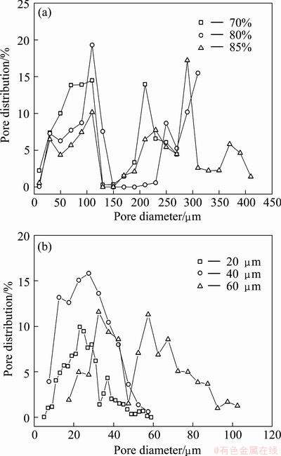
Fig. 5 Pore diameter distribution of PMFSF (a) and commercial porous felt (b)
The above distinguishable difference between these two porous sintered metals can be ascribed to their different processing methods and structural features. On one hand, the bundle-drawn fiber has much smoother surface and a smaller diameter ranging from several μm to tens of micron, so that the pores can be constructed in a more uniform manner. As a result, the commercial felt based on such fibers has better consistency in pore distribution. On the other hand, the cutting-based metal fiber mostly has bulky size, rough surface and irregular structure. This inevitably results in diverse pore diameter and distribution under a random condition. In addition, the industrial spreading method is more able to ensure uniform fiber distribution than the manual manipulation. This is also a possible reason for their difference in pore distribution. As is well known, when the porous material is used for filtration, a uniform but narrowly-distributed pore structure is necessarily required. Nevertheless, under condition that the PMFSF is used as a mass-transfer-controlling medium in a passive air-breathing DMFC, its wide and polarized pore distribution becomes an advantage with the large pores acting as permeable passages while the small pores acting as barriers. This illuminates the feasibility of alleviating the conflict between the methanol supply and methanol crossover control.
3.2 Fluid flow characteristics of porous metal fiber sintered felt
According to Eqs. (3) and (4), the permeability coefficients in correspondence with 70%, 80% and 90% PMFSFs can be calculated to be 9.03×10⁻¹¹, 2.17×10⁻¹¹ and 5.50×10⁻¹⁰, respectively. All these values were far lower than the amplitude of 10-8 which is regarded as a critical level discriminating the grooved and porous flow fields [18,19]. Evidently, such a porous diffusion medium is favorable to enhance the fuel efficiency due to its lower permeability. Figure 6 shows the fluid flow characteristics of the PMFSFs. It is observed from Fig. 6(a) that with the increase of porosity, mass flow rate can be enhanced in a wide range of pressure. This can be also inferred from Fig. 6(b) that a higher porosity with a larger pore size promotes the reduction of mass flow resistance.
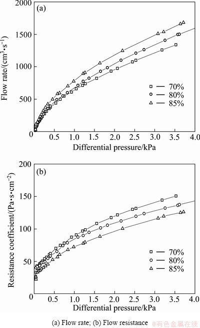
Fig. 6 Effects of PMFSF porosity on fluid flow characteristics
As shown in Fig. 7, the commercial SUS316L felt based on buddle-drawn fibers provides a much higher resistance to mass flow than the self-made PMFSF. This phenomenon again verifies a fact that the fluid flow characteristic of a porous material is closely affected by the structural factor. This result highlights the feasibility of controlling its permeability by regulating its structural properties so as to meet different demands in different application environments.

Fig. 7 Effects of commercial felt porosity on fluid flow characteristics
3.3 Wettability of porous metal fiber sintered felt
Figure 8 describes the porosity dependency of the wettability of a PMFSF. It can be seen that the PMFSF exhibits great hydrophobicity because all the measured contact angles are far higher than 90°. This feature is totally different from that of the commercial SUS316L felt which is too hydrophilic to hold water on its surface. A tendency can be also observed that with the increase of porosity, the contact angle gradually increases, which shows evident resistance to liquid invasion. According to Eq. (2), it is understandable that the capillary pressure is inversely proportional to the pore diameter. In addition, this result can be also explained by the fact that the wetting liquid is more able to fill in a pore or a gap with a smaller curvature radius.
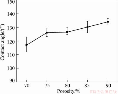
Fig. 8 Contact angles of PMFSF with different porosities
3.4 Performance evaluation of passive air-breathing DMFC with anodic PMFSF
As aforementioned, in order to alleviate the effects of methanol crossover, the prepared PMFSF was used as a methanol barrier layer for balanced control of the methanol transport at the anode. Figure 9 compares the cell performances of a small-scale passive air-breathing DMFC when a PMFSF and a commercial SUS316L felt are respectively used. For comparison, the cell performance without any barrier layer is also provided as a reference. The data were acquired when a very high methanol concentration of 12 mol/L was used. Results suggest that when the cell uses a PMFSF-based barrier, its performance is considerably improved since the voltage drop becomes slower. Notably, the peak power density (PPD), limiting current density (LCD) and open circuit voltage (OCV) are all enhanced. This means that the use of a PMFSF enables the fuel cell to be operated in a wider range of load change with a higher voltage output. Contrarily, when a commercial felt based on bundle-drawn fibers is involved, the cell performance is drastically reduced to an even lower level than that without a methanol barrier layer. This distinct performance can be interpreted by structural aspects of the porous sintered metals. It is understandable that the commercial felt owns a very small pore size and has an excessively high resistance. This inevitably holds back methanol delivery so that the fuel cell may increasingly suffer concentration-induced polarization with the increase of current density especially when the cell operates in a fully-passive mode. Concurrently, a plenty of CO2 bubbles are produced at a relatively higher methanol concentration of 12 mol/L. In this case, a too high structural resistance tends to hinder CO2 removal and results in passage blockage, which further slows down methanol permeation. Figure 10 describes the dynamic behaviors of the OCVs over 10 min testing when different structures are used. In the early stage, the value of OCV overshoots to a peak point and then steeply drops to a certain value. After this, the OCV drops more slowly until reaching a stable level. All these different stages correspond to different mass transfer processes of the methanol fuel. The final state represents a concentration balance of the methanol at both sides of the membrane, at which a stabilized value of OCV can be obtained. Compared with the traditional cell structure without a barrier layer, the PMFSF improves the OCV. It is also worth noting that the commercial felt has a lower peak of OCV, since the passive fuel cell encounters a great challenge of methanol delivery at the early stage. Thus, it can be inferred that the issue related to methanol supply overwhelms the methanol crossover when a lower porosity is adopted.

Fig. 9 Performance between passive air-breathing DMFCs with PMFSF and commercial SUS316L felt (12 mol/L)

Fig. 10 Dynamic characteristics of open circuit voltages under different structural conditions (12 mol/L)
The influence of PMFSF structure on the bubble behaviors can be also visualized in Fig. 11. It is clear that under the same condition, more CO2 bubbles escape from the 80% PMFSF than the commercial felt since a smaller pore size inevitably inhibits fast formation of larger bubbles. In addition, water transport is also limited by such a compact structure, which possibly leads to a reduced level of membrane hydration. This is a contributing factor to excessive ohmic losses. All these effects reduce the cell performance in a great extent or even cause operation failure. In comparison, the PMFSF with both small and large pores is more competent in improving methanol and water supply, promoting gas exhaust and also restricting methanol crossover. In other words, using this permeable but resistant material as a mass-transfer-controlling medium facilitates an appropriate balance between reactant and product management especially when the DMFC is operated in a passive mode. Furthermore, it is worth noting that, the effect of hydrophobicity should be also taken into account, which holds back the transport of methanol solution. Results further suggest that a lower porosity of 70% yields a better performance than 80%. Therefore, it can be concluded that there exist an optimum structure and an optimal mass transfer resistance of the methanol barrier.
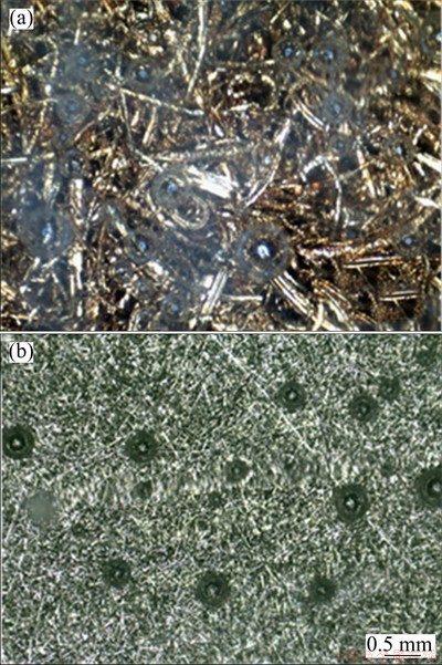
Fig. 11 Anode bubble behaviors of passive air-breathing DMFCs with 80% PMFSF (a) and commercial SUS316L felt (b)
Figure 12 shows the effects of the methanol concentration on the cell performance when 70% PMFSF is used. It is clearly observed that the cell performs the best at a methanol concentration of 4 mol/L which doubles the optimal methanol concentration in a traditional passive DMFC [20]. This just reflects the merit of introducing a barrier layer that both the energy density and operating time can be enhanced. Another noticeable phenomenon is that 0.5 mol/L methanol yields a comparable value of PPD to 4 mol/L, but a very low value of LCD. This is because the concentration polarization more severely happens due to methanol starvation in the high-current region.

Fig. 12 Effects of methanol concentration on cell performance with 70% PMFSF
4 Conclusions
1) This self-made PMFSF is typical of larger pore size, wider and multiple-peak pore diameter distribution, irregular fiber shape, rougher surface, lower mass flow resistance and hydrophobicity.
2) The DMFC incorporating such a porous barrier layer gains a significant performance improvement since it promotes a balanced management of methanol supply and product removal while reducing the methanol crossover.
3) The PMFSF with a porosity of 70% produces the highest cell performance. The optimal methanol concentration is 4 mol/L.
References
[1] EVANS A G, HUTCHINSON J W, ASHBY M F. Multifunctionality of cellular metal systems [J]. Progress in Materials Science, 1999, 43(3): 171-221.
[2] LEFEBVRE L P, BANHART J, DUNAND D C. Porous metals and metallic foams: Current status and recent developments [J]. Advanced Engineering Materials, 2008, 10(9): 775-787.
[3] CHEN Liang-jian, LI Ting, LI Yi-min, HE Hao, HU You-hua. Porous titanium implants fabricated by metal injection molding [J]. Transactions of Nonferrous Metals Society of China, 2009, 19(5): 1174-1179.
[4] DEWIDAR M M, KHALIL K A, LIM J K. Processing and mechanical properties of porous 316L stainless steel for biomedical applications [J]. Transactions of Nonferrous Metals Society of China, 2007, 17(3): 468-473.
[5] CHIBA A, NOMURA N, ONO Y. Microstructure and mechanical properties of biomedical Co-29Cr-8Mo alloy wire fabricated by a modified melt-spinning process [J]. Acta Materialia, 2007, 55(6): 2119-2128.
[6] HANAZAKIA K, SHIGEIRI N, TSUJI N. Change in microstructures and mechanical properties during deep wire drawing of copper [J]. Materials Science and Engineering A, 2010, 527(21-22): 5699-5707.
[7] ZHOU W, TANG Y, PAN M, WEI X, XIANG J. Experimental investigation on uniaxial tensile properties of high-porosity metal fiber sintered sheet [J]. Materials Science and Engineering A, 2009, 525(1-2): 133-137.
[8] WAN Z P, TANG Y, LIU Y J, LIU W Y. High efficient production of slim long metal fibers using bifurcating chip cutting [J]. Journal of Materials Processing Technology, 2007, 189(1-3): 273-278.
[9] LI X, GONG R, NIE Y, ZHAO Z, HE H. Electromagnetic properties of Fe55Ni45 fiber fabricated by magnetic-field-induced thermal decomposition [J]. Materials Chemistry and Physics, 2005, 94(2-3): 408-411.
[10] MITCHELL P J. Current distributors of sintered metals and fuel cells using them: US Patent WO/1998/052241 [P]. 1998.
[11] TANG Y, YUAN W, PAN M Q, WAN Z P. Feasibility study of porous copper fiber sintered felt: A novel porous flow field in proton exchange membrane fuel cells [J]. International Journal of Hydrogen Energy, 2010, 35(18): 9661-9677.
[12] HOTTINEN T, MIKKOLA M, MENNOLA T, LUND P. Titanium sinter as gas diffusion backing in PEMFC [J]. Journal of Power Sources, 2003, 118(1-2): 183-188.
[13] HOTTINEN T, HIMANEN O, LUND P. Effect of cathode structure on planar free-breathing PEMFC [J]. Journal of Power Sources, 2004, 138(1-2): 205-210.
[14] BROWN J. Design, processing, and characterization of composite metal foams for fuel cell applications [R]. USA: North Carolina State University, 2009.
[15] LIU J, SUN G, ZHAO F, WANG G, ZHAO G, CHEN L, YI B, XIN Q. Study of sintered stainless steel fiber felt as gas diffusion backing in air-breathing DMFC [J]. Journal of Power Sources, 2004, 133(2): 175-180.
[16] XU C, FAGHRI A, LI X, WARD T. Methanol and water crossover in a passive liquid-feed direct methanol fuel cell [J]. International Journal of Hydrogen Energy, 2010, 35(4): 1769-1777.
[17] JENA A, GUPTA K. Liquid extrusion techniques for pore structure evaluation of nonwovens [J]. International Nonwovens Journal, 2003: 45-53.
[18]  E, ESCUDERO M J, BAUTISTA C,
  P L, DAZA L. Optimisation of flow-field in polymer electrolyte membrane fuel cells using computational fluid dynamics techniques [J]. Journal of Power Sources, 2000, 86(1-2): 363-368.
[19] KUMAR A, REDDY R G. Modeling of polymer electrolyte membrane fuel cell with metal foam in the flow-field of the bipolar/end plates [J]. Journal of Power Sources, 2003, 114(1): 54-62.
[20] YUAN W, TANG Y, YANG X J, LIU B, WAN Z P. Structural diversity and orientation dependence of a liquid-fed passive air-breathing direct methanol fuel cell [J]. International Journal of Hydrogen Energy, 2012, 37(11): 9298-9313.
袁 伟,汤 勇,杨晓军,刘 彬,万珍平
华南理工大学 机械与汽车工程学院,表面功能结构先进制造广东普通高校重点实验室,广州 510640
摘 要:基于多齿刀具切削连续型金属长纤维及高温固相烧结技术,对多孔金属纤维烧结毡(PMFSF)的制造工艺、表征及性能进行研究,并将其应用于被动式自呼吸直接甲醇燃料电池阳极,作为传质控制介质以缓解甲醇穿透而造成的负面影响。与商业化多孔金属纤维烧结毡相比,利用该工艺制得的PMFSF具有较大孔径,孔径分布呈现多峰极化特性,纤维呈随机非规则排列,表面粗糙,因而可获得较大的传质阻力及疏水性。结果表明,采用PMFSF作为电池阳极传质控制介质,能够实现反应物和产物传递过程的平衡管理,因而使电池性能得到显著提升。当PMFSF的孔隙率为70%,甲醇浓度为4 mol/L时,电池的性能达到最优。
关键词:多孔金属;金属纤维;烧结毡;切削;孔径分布;燃料电池
(Edited by Xiang-qun LI)
Foundation item: Projects (50930005, 51075155) supported by the National Natural Science Foundation of China; Project (20100172110001) supported by PhD Programs Foundation of Ministry of Education of China
Corresponding author: Wei YUAN; Tel/Fax: +86-20-87114634; E-mail: mewyuan@scut.edu.cn
DOI: 10.1016/S1003-6326(13)62700-4

