渗碳处理对95W-3.4Ni-1.6Fe高比重合金显微组织和接触疲劳性能的影响
来源期刊:中国有色金属学报(英文版)2016年第12期
论文作者:王光宏 屈盛官 和锐亮 胡可 李小强
文章页码:3161 - 3169
关键词:钨合金;接触疲劳;渗碳;剥落
Key words:tungsten alloy; rolling contact fatigue; carburization; spalling
摘 要:采用固体渗碳法对95W-3.4Ni-1.6Fe高比重合金进行了渗碳处理,并在球棒试验机上研究了渗碳处理对钨合金接触疲劳性能的影响。利用SEM、EDS、XRD、表面形貌仪等手段对渗碳钨合金的显微组织和疲劳损伤形貌等进行了表征。结果表明,渗碳处理后钨合金表面由较薄的多孔碳化钨层和被碳化钨包裹的改性钨颗粒层组成。渗碳处理不仅降低了钨合金的接触疲劳性能而且加剧了对偶件钢球的磨损。钨合金的损坏机制为剥落和层状分离,次表层主裂纹易在最大剪切应力处萌生并沿着钨–钨界面扩展。渗碳钨合金的损坏是由碳化钨颗粒的剥落造成,同时剥落后的碳化钨颗粒在接触界面间充当第三体,加剧了渗碳钨合金的表面磨损。
Abstract: 95W-3.4Ni-1.6Fe heavy alloy was carburized by pack carburization. Microstructure and hardness of the carburized alloy were investigated by SEM, EDS XRD. Effect of carburization on the rolling contact fatigue (RCF) property of the alloy was studied. The results showed that the carburized layer was composed of the outer, porous WC layer and the modified subsurface layer with each W grain surrounded by a WC shell. Carburization not only decreased the RCF performance of the alloy but also aggravated the wear of the counter balls. The untreated alloy was damaged by two modes of spalling and delamination under RCF condition. The subsurface main crack of the untreated alloy initiated where the maximum shear stress existed and preferentially propagated along the W-W interfaces. Spalling was the main failure mode of the carburized alloys, and the crumbling WC particles intensified the abrasion of the carburized surface.
Trans. Nonferrous Met. Soc. China 26(2016) 3161-3169
Guang-hong WANG, Sheng-guan QU, Rui-liang HE, Ke HU, Xiao-qiang LI
National Engineering Research Center of Near-net-shape Forming Technology for Metallic Materials, South China University of Technology, Guangzhou 510640, China
Received 4 November 2015; accepted 23 March 2016
Abstract: 95W-3.4Ni-1.6Fe heavy alloy was carburized by pack carburization. Microstructure and hardness of the carburized alloy were investigated by SEM, EDS XRD. Effect of carburization on the rolling contact fatigue (RCF) property of the alloy was studied. The results showed that the carburized layer was composed of the outer, porous WC layer and the modified subsurface layer with each W grain surrounded by a WC shell. Carburization not only decreased the RCF performance of the alloy but also aggravated the wear of the counter balls. The untreated alloy was damaged by two modes of spalling and delamination under RCF condition. The subsurface main crack of the untreated alloy initiated where the maximum shear stress existed and preferentially propagated along the W-W interfaces. Spalling was the main failure mode of the carburized alloys, and the crumbling WC particles intensified the abrasion of the carburized surface.
Key words: tungsten alloy; rolling contact fatigue; carburization; spalling
1 Introduction
Tungsten heavy alloys (WHAs) typically consist of W grains and a ductile matrix phase. WHAs are generally used in military and civil areas such as kinetic energy (KE) penetrators, electronic contact, counter weights and radiation shields owing to their high density, excellent conductivity, high temperature and corrosion resistance, and good mechanical properties [1-7]. For extending the applications of WHAs, improving the mechanical properties of bulk WHAs has been focused on from different angles including tungsten grain refinement [8-13], dispersion reinforcing by adding oxides or carbides [14-18], deformation strengthening [19-21], and developing advanced sintering techniques [22-25]. Meanwhile, tungsten content was revealed to have an effect on the microstructure and the mechanical properties of the WHAs [26,27]. Especially, the plain fatigue properties of three kinds of WHAs (D176, IT180, and D185) were demonstrated to be strongly affected by surface rough-ness, residual porosity, pore size and the distribution of the ductile phase. And the principal fracture mechanism under fatigue loading observed in D176 and D185 alloys was tungsten grain cleavage [28,29]. In the case of IT180 heavy alloy, intergranular failure by separation of W-W interfaces was predominant [29].
Rolling contact fatigue (RCF) is one of the typical surface damage modes for the moving parts in industrial applications including gears, bearings, tappets, electric contact, the rotor in the instrument, and gyrowheel. When these parts fail, it always decreases the service stability and lifetime of the whole machine. Generally, the cracks of RCF may be initiated either beneath the contacting surface or on the surface, causing the spalling or delamination on the surface of bodies in the rolling or rolling/sliding contacts. Therefore, surface enhanced techniques to resist RCF are widely investigated. Carburization is a classical approach to improve the tribological properties of various kinds of steels [30,31], and pure iron [32]. In addition, carburization was also revealed to harden the surface of WHAs by the formation of tungsten carbide (WC), sub-carbide (W2C) or a combination of them. Meanwhile, penetration performance of the WHAs was enhanced by carburization, which was related to the cleavage fracture mode of tungsten particles beneficial for self-sharping [33]. However, the RCF property of the WHAs and especially the effect of carburization on the RCF property of the WHAs have not been reported. In the present work, the RCF performance of the carburized 95W-3.4Ni-1.6Fe heavy alloy was investigated compared with the untreated alloy. Additionally, the research is aimed to identify the failure mechanism of the untreated and carburized WHAs.
2 Experimental
2.1 Material preparation
Two different sizes of WHA (95W-3.4Ni-1.6Fe, mass fraction, %) samples were prepared. The fatigue samples were machined into cylindrical rods with a diameter of 10 mm and a length of 140 mm; the other specimens were cut into cubes with the dimensions of 10 mm ×10 mm ×10 mm for metallographic and surface property observations. Before carburization, all of the WHA samples were ground to reach the same surface roughness (Ra≈0.35), and then cleaned ultrasonically in petroleum ether. Pack carburization was completed for 10 h and 30 h (referred as C10 and C30, separately) with employing sodium carbonate as a catalyst.
2.2 Microstructure characterization and RCF tests
Microstructure and linescan microanalyses of the WHA specimens were examined using a FEI Nova 430 SEM with an energy dispersive spectrometer (EDS) system. Surface profile was examined using a BMT Expert3D profiler device. The phase structures of the WHA samples were detected by X-ray diffraction (XRD) on a D8 ADVANCE diffractometer with Cu Kα (λ=1.54056  ) excitation radiation and the scan angle (2θ) from 30° to 90°. The RCF property of the WHA was tested on a three ball-on-rod RCF testing machine at room temperature, and the schematic of the tester is described in Fig. 1. The test rods rotated against three balls which were made of the AISI52100 steel with a hardness of HRC 60 at a speed of 1800 r/min, corresponding to 2.49×10⁵ cycles between the rod and balls in 1 h of testing. The rolling contacts were lubricated by Mobil 0W-40CF oil. The normal load maintained 900 N, corresponding to the maximum Hertz contact pressure of 6 GPa using the classical Hertzian theory. In this case, the maximum shear stress (τmax) and depth were calculated to be 2.08 GPa and 132.86 μm, and the calculation method can be referred to the previous work [34]. The machine ran until the surface of any of the rolling parts was damaged, which caused a significant increase of the vibration level, monitored by an acceleration transducer. Once the vibration level exceeded the preset value, the machine stopped automatically; at this time, the time interval which the rod rolled against the balls was automatically reported by the computer. Because the RCF lifetime usually presents highly discrete, ten times measurements were completed for every group alloy. After the tests, all of the rolling elements and the retainer were ultrasonically cleaned in petroleum ether. The failure mechanism of the samples was analyzed by the SEM, EDS and profile analysis of the worn surface.

Fig. 1 Schematic diagram of three-ball-on-rod tester
3 Results and discussion
3.1 Microstructure
Figure 2(a) shows the surface XRD patterns of the untreated, C10, and C30 WHAs. For the untreated alloy, the strongest diffraction peak is W phase, which is expected related to the high proportion (95%) of the mixed powders. Meanwhile, weak peaks of the matrix phase, i.e., γ-(Ni, Fe) solid solution, are observed in the alloy. In contrast, W grains have been fully converted to WC on the carburized surface regardless of the carburizing time. Figure 2(b) shows the microstructure and EDS analysis of the untreated WHA. The white and global particles represent the W grains, whereas the small and black one is the γ-(Ni, Fe) binding phase. The W grains are uniformly dispersed in the matrix phase before the RCF tests. Figure 2(c) shows the cross-sectional microstructure of the C10 alloy. There are three zones for the carburized layer. The unreacted core is named U zone in the right of the blank line. The outer reacted surface is WC layer, labeled as R1 zone separated by the red line. Figure 2(d) shows the magnified microstructure of the outer WC layer. A porous structure can be seen clearly. The depth of WC layer of the C10 alloy is 2-4 μm. Similarly, the depth of WC layer of the C30 alloy is 4-6 μm. The W grains on the subsurface are surrounded by a shell, and the magnified microstructure is given in Fig. 2(e). In order to make clear what the shell is, the outer layer of the C10 alloy was cut down, where the location can be labeled as the blue line in Fig. 2(c). Figure 2(f) shows the subsurface XRD patterns of the C10 and C30 alloys. Except for the matrix and W peaks, WC peaks are strong. This suggests that the shell is WC phase. The formation of the WC shell outside the W particles restricted the diffusion of carbon, so more time was needed to complete the carburization process. The depths of the middle layer of the C10 and C30 alloys are approximately 140 μm and 190 μm, respectively. Thus, it can be included that the carburized layer is composed of the outer, porous WC layer and the subsurface layer with each W grain surrounded by a WC shell. Moreover, the depth of the carburized layer increased with the increasing carburizing time.
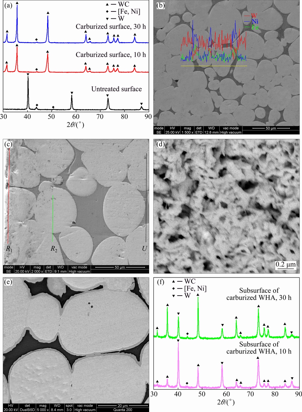
Fig. 2 XRD patterns of untreated and carburized alloy (a), microstructure and element distribution of untreated alloy (b), cross-sectional microstructure of C10 alloy (c), magnified microstructure of R1 and R2 zones of C10 alloy (d, e), and subsurface XRD patterns of C10 and C30 alloys (f)
3.2 Weibull distribution
After the RCF tests, the cycles that the rods experienced can be calculated by the equations referred to Ref. [35]. Two-parameter Weibull distribution was employed to characterize the RCF life of the tested WHAs. Figure 3 shows the Weibull curves of the fatigue life of the untreated and carburized alloys using a confidence level of 95%. The ordinate axis illustrates the failure probability of the rod specimens while the abscissa represents the number of stress cycles to fail. The fatigue life of the samples displays highly discrete characteristics. From the Weibull distribution, the L10, L50, L63.2 lives which are also named characteristic life La and Weibull slope (β) for the untreated and carburized alloys can be read and listed in Table 1. The L10, L50, La lives and the value of shape parameter (β) of the untreated alloy are 1.654×10⁵, 2.985×10⁵, and 3.348×10⁵ cycles and 3.191 under the maximum Hertz contact pressure of 6 GPa, respectively, which are larger than those of the C10 and C30 alloys. Further, the RCF lifetime of C30 alloy is shorter than that of the C10 alloy. The results indicate that carburization decreased the RCF lifetime of the WHA. Further, prolonging the carburizing time was invalid to improve the RCF performance of the WHA.

Fig. 3 Weibull plots of fatigue life of untreated and carburized alloys using 95% confidence level
Table 1 Typical RCF life and Weibull curve slope of tested alloys

3.3 Worn surface observation and failure mechanism analysis
To identify the failure mechanism of the untreated and carburized alloys, the worn surfaces of the failure samples were examined. Figure 4 shows the worn surfaces of the untreated alloy with different RCF lives. The untreated alloy specimens were damaged by two main modes, i.e., spalling and delamination. The main failure mode of each specimen is listed in Table 2. The untreated samples failed in the delamination mode are more than those failed in the spalling mode. Figure 4(a) shows the spalling morphology of the failed specimen with a fatigue life of 3.5×10⁵ cycles. There are some typical pittings on the worn surface. Figure 4(b) shows the magnified micrograph of the zone tagged by the blue ellipse in Fig. 4(a). Although the white particles represent W phase and the black zone is γ-(Ni, Fe) phase demonstrated by the spectra in Figs. 4(c) and (d), the W particles were strongly deformed to be ellipsoidal and the particles aggregation of binding matrix took place. The aggregation of the binding matrix causes a severe increases of the tungsten–tungsten interfaces in Fig. 4(b). There are four kinds of fracture modes [36] in a WHA: cleavage of the tungsten grain (Wc); avulsion of the matrix (Ma); interface separation of the tungsten grain and the matrix (W-M); interface separation of the tungsten grains (W-W). Among the four kinds of fracture modes, the binding strength of W-W interfaces is the weakest to resist the failure load, so that the increase of the W-W interface means an increase of the weaker binding interface. It will cause the occurrence probability of the nucleation, growth and connection of RCF cracks at the W-W interface greatly increasing under the actions of an alternating force. The numerous cracks at the W-W interfaces are pointed out by the red arrows. The ring-type crack formed when the single crack at W-W interface connected with each other, denoted as the arcs in Figs. 4(a) and (b). The ring-type crack can be often found in some typical and structural materials under the rolling contact such as nitrided steel [34], coatings [37], and silicon nitride ceramic [38]. Figure 4(e) shows the overall view of the delamination mode with a RCF life of 1.8×10⁵ cycles. There are also ring-type cracks generated along the W-W interface. Figure 4(f) shows the magnified morphology of the worn surface, located by the ellipse in Fig. 4(e). In Fig. 4(f), the transgranular fracture (Wc) can be seen clearly by the arrow, which is not easy to occur in the plain fracture such as tensile and impact failure because it needs more energy [39]. A W grain is surrounded by cracks displayed by the ellipse in Fig. 4(f), which rarely appeared in this work. Furthermore, the deformation of the body outside the worn zone displays different characteristics. The deformation direction in different locations and the rolling direction form an obtuse angle (referred to α). However, the obtuse angle next to the worn zone is larger than that distant from the worn zone, which is associated with the action of shear force. It can be also seen that the deformation of the body in the delamination mode is more severe than that in the spalling mode in Fig. 4(a). The previous, global W grains were deformed to be oblate.

Fig. 4 Worn surfaces of untreated WHA
Table 2 Main failure mode for each sample under maximum Hertz contact pressure of 6 GPa

Figure 5(a) shows the overview of the delamination of the untreated alloy with a RCF life of 2.95×10⁵ cycles, accompanied with a spalling. A large scale of body with some main cracks vertical to the rolling direction on its surface hangs upon the substrate. Figure 5(b) gives the cross-sectional and magnified observation of the spalling tagged by the dotted line 2 in Fig. 5(a). The subsurface main cracks can be seen clearly, which is parallel to the rolling direction, denoted by the green arrows. The second cracks appeared next to the final fracture location, labeled by the blue arrows, and propagated into the body along the W-W interface. From the magnified morphology of the spalling, we can see a pore at the end of the ring-type crack. The pore has not reached the contact interface and the fracture could not spread to this point, which means the ring-type crack grew on the subsurface. Generally, the ring-type crack can propagate both upwards to the surface and downwards into the body [38]. In the rectangle frame of Fig. 5(b), the W grains were strongly deformed in the radial direction because they suffered the heavy, normal, and alternating loads. Therefore, the fibrous microstructure appeared, which was revealed in Ref. [40]. Moreover, the amount of deformation of the samples in the radial direction is larger than that parallel to the rolling direction. Figure 5(c) shows the surface profile of the worn surface labeled by the dotted line 1 in Fig. 5(a). In Fig. 5(c), the depth of the spalling can be deemed as 31.06 μm, which is relatively identical to the depth of the maximum shear stress of 132.86 μm. In addition, there are two shoulders at the edge of the contact due to the plastic deformation of the body under the alternating loads. The depth of the spalling and delamination of each untreated, damaged sample was obtained by examining the profiles of the failure specimens, which is described in Fig. 5(d). Most of the depths of the profiles were close to the depth of the maximum shear stress. This indicates that the subsurface main crack initiated from the subsurface where the maximum shear stress existed and propagated in parallel to the rolling direction along the W-W interface. Therefore, the formation of final fractures (both spalling and delamination) was caused by the linking of the subsurface main crack and the ring-type crack.

Fig. 5 Overall view of delamination of untreated alloy with a RCF life of 2.95×10⁵ cycles (a), cross-sectional and magnified observation (b) in subsurface of spalling indicated by dash 2 in (a), surface profile (c) of delamination indicated by dash 1 in (a) and depths obtained by worn profile of each untreated, worn specimen (d)
Figure 6(a) shows the overall view of the worn surface of the C10 alloy with a RCF life of 1.5×10⁵ cycles. It presents a “U” shape which is low in the center and high on both sides. This correlates with the distribution of the normal load. The normal load decreased from the center to the side under the rolling contact. The deformation of the subsurface body in the center was more intense than that at the edges. Figure 6(b) shows the magnified morphology of the selected zone in Fig. 6(a). Spalling of WC particles left lots of pits indicated by the ellipses. There were two reasons for the spalling of WC particles. On one hand, the adhesive strength between WC and WC particles was weak. Meanwhile, WC phase was brittle and difficult to deform. Thus, WC particles were easy to spall off from the surface under the alternating loads. On the other hand, perhaps the surface could not undergo the heavy normal load and be collapsed due to its porous structure in WC layer. These are also helpful to explaining why carburization decreased the RCF lifetime of the WHA. The surface was also severely destroyed by abrasion. WC particles are hard and sharp. Peeling WC particles acted as the third body rather than to be a roller like the sub-micron spherical silica particles at the interfaces of the balls and rod and intensified the abrasion of the carburized surface [41,42], demonstrated by many deep and wide furrows.
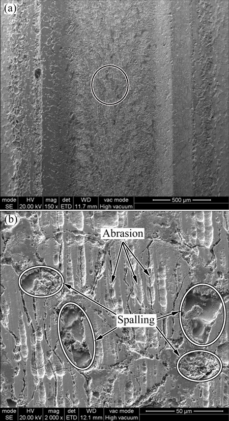
Fig. 6 Overall view of worn surface of C10 alloy with RCF life of 1.5×10⁵ cycles (a), and its magnified observation (b) of selected zone by blank ellipse in (a)
Figure 7 shows the surface profiles of the unused ball and the balls rolling against different counter rods. It is an arc for the unused ball surface. The surface shape of the ball rolling against the untreated alloy is similar to that of the unused ball. It indicates that the ball surface was scarcely damaged by the untreated alloy. However, the surface profiles of the balls rolling against the carburized alloys are significantly different from that the unused ball. The top becomes a straight line rather than an arc. Especially, the edges of the contact zone present obvious material defects. At the beginning, the normal maximum stress located at the center. The central material of the ball was worn by the hard WC layer and the subsurface body of the carburized alloy deformed under the alternating normal loads. With the test proceeding and the removal of the material in the center, normal stress distribution changed and the edges suffered main normal stress at some stage. At this time, the pure rolling transformed into rolling/sliding. The edges of the balls were seriously damaged. This indicates that the wear resistance of the WHA itself was improved by the formation of the hard WC layer through pack carburization. However, the RCF performance of the carburized alloys was not better than that of the untreated alloy. Generally, high strength and high hardness can increase the wear resistance. High ductility and high toughness can prolong the RCF life.

Fig. 7 Surface profiles of unused ball and balls against different counter rods
4 Conclusions
1) The calculated depth and the maximum shear stress are respectively 132.86 μm and 2.08 GPa under the maximum Hertz contact pressure of 6 GPa. After carburization, the surface of the WHA was composed of the outer, porous WC layer and the subsurface layer with each W grain surrounded by a WC shell. Moreover, the depth of the carburized layer increased with the carburizing time. Carburization not only decreased the RCF performance of the WHA but also aggravated the wear of the counter balls regardless of the carburizing time.
2) The W grains of the untreated alloy were severely deformed and especially the fibrous microstructure appeared in the radial direction under the action of alternating loads. The untreated alloy was damaged by two modes, i.e., spalling and delamination. The ring-type crack was initiated on the subsurface of the body and the subsurface main crack initiated from the location where the maximum shear stress existed. The RCF cracks preferred to initiating and propagating along the W–W interface. The final fracture was caused by the linking of the subsurface main crack and the ring-type crack.
3) The main failure mechanism of the carburized alloys was spalling with the abrasion because of the hard and sharp WC particles acting a third-body at the rolling contact. The same failure mechanism is that prolonging the carburizing time cannot improve the RCF performance of the WHA.
References
[1] HU K, LI X Q, YANG CH, LI Y Y. Densification and microstructure evolution during SPS consolidation process in W-Ni-Fe system [J]. Transactions of Nonferrous Metals Society of China, 2011, 21: 493-501.
[2] KIRAN U R, RAO A S, SANKARANARAYANA M, NANDY T K. Swaging and heat treatment studies on sintered 90W-6Ni-2Fe-2Co tungsten heavy alloy [J]. Int J Refract Met Hard Mater, 2012, 33: 113-121.
[3] LI X Q, XIN H W, HU K, LI Y Y. Microstructure and properties of ultra-fine tungsten heavy alloys prepared by mechanical alloying and electric current activated sintering [J]. Transactions of Nonferrous Metals Society of China, 2010, 20: 443-449.
[4]  KARAKAYA
  , KALKANLI A. Processing and microstructural characterization of liquid phase sintered tungsten–nickel–cobalt heavy alloys [J]. Int J Refract Met Hard Mater, 2015, 50: 106-112.
[5] LI Y Y, HU K, LI X Q, AI X, QU SH G. Fine-grained 93W-5.6Ni-1.4Fe heavy alloys with enhanced performance prepared by spark plasma sintering [J]. Mater Sci Eng A, 2013, 573: 245-252.
[6] KHALID F A. Characterization of in-situ carbide coating of tungsten alloy [J]. Mater Sci Eng A, 2002, 338: 76-80.
[7] KOBAYASHIA A, SHARAFAT S, GHONIEM N M. Formation of tungsten coatings by gas tunnel type plasma spraying [J]. Surf Coat Tech, 2006, 200: 4630-4635.
[8] LIU G Y, NI S, SONG M. Effect of indentation size and grain/sub-grain size on microhardness of high purity tungsten [J]. Transactions of Nonferrous Metals Society of China, 2015, 25: 3240-3246.
[9] MA B, RAO Q H, HE Y H. Effect of crystal orientation on tensile mechanical properties of single-crystal tungsten nanowire [J]. Transactions of Nonferrous Metals Society of China, 2014, 24: 2904-2910.
[10] LUO A, SHIN K S, JACOBSON D L. Effects of thoria particles on the high-temperature tensile properties of a W-26wt.%Re alloy [J]. Mater Sci Eng A, 1992, 150: 67-74.
[11] HSU C, LIN S. Coalescence of tungsten grains around molybdenum grains in the presence of a liquid phase [J]. Scripta Mater, 2002, 46: 869-873.
[12] KEMP P B, GERMAN R M. Mechanical properties of molybdenum alloyed liquid phase-sintered tungsten-based composites [J]. Metall Mater Trans A, 1995, 26: 2187-2189.
[13] BOSE A, GERMAN R M. Microstructural refinement of W-Ni-Fe heavy alloys by alloying additions [J]. Metall Mater Trans A, 1988, 19: 3100-3103.
[14] CHEN CH L, HUANG CH L. Milling media and alloying effects on synthesis and characteristics of mechanically alloyed ODS heavy tungsten alloys [J]. Int J Refract Met Hard Mater, 2014, 44: 19-26.
[15] LUO A, SHIN K S, JACOBSON D L. High temperature tensile properties of WReThO2 alloys [J]. Mater Sci Eng A, 1991, 148: 219-229.
[16] PARK S, KIM D, LEE S, RYU H J, HONG S H. Dynamic deformation behavior of an oxide-dispersed tungsten heavy alloy fabricated by mechanical alloying [J]. Metall Mater Trans A, 2001, 32: 2011-2020.
[17] RYU H J, HONG S H. Fabrication and properties of mechanically alloyed oxide-dispersed tungsten heavy alloys [J]. Mater Sci Eng A, 2003, 363: 179-184.
[18] WU G C, YOU Q, WANG D. Influence of the addition of lanthanum on a W-Mo-Ni-Fe heavy alloy [J]. Int J Refract Met Hard Mater, 1999, 17: 299-304.
[19]  Swaging of liquid phase sintered 90W-7Ni-3Fe tungsten heavy alloy [J]. Int J Refract Met Hard Mater, 2013, 36: 260-264.
[20] EKBOM L, ANTONSSON T. Tungsten heavy alloy: Deformation texture and recrystallization of tungsten particles [J]. Int J Refract Met Hard Mater, 2002, 20: 375-379.
[21] ZHANG ZH H, WANG F CH, LI SH K, WANG L. Deformation characteristics of the 93W-4.9Ni-2.1Fe tungsten heavy alloy deformed by hydrostatic extrusion [J]. Mater Sci Eng A, 2006, 435-436: 632-637.
[22] CHEN B H, CAO SH H, XU H, JIN Y, LI SH K, XIAO B. Effect of processing parameters on microstructure and mechanical properties of 90W-6Ni-4Mn heavy alloy [J]. Int J Refract Met Hard Mater, 2015, 48: 293-300.
[23] UPADHYAYA A, TIWARI S K, MISHRA P. Microwave sintering of W-Ni-Fe alloy [J]. Scripta Mater, 2007, 56: 5-8.
[24] SONG X, LIU X, ZHANG J. Neck formation and self-adjusting mechanism of neck growth of conducting powders in spark plasma sintering [J]. J AM Ceram Soc, 2006, 89: 494-500.
[25] HU K, LI X Q, QU SH G, LI Y Y. Effect of heating rate on densification and grain growth during spark plasma sintering of 93W-5.6Ni-1.4Fe heavy alloys [J]. Metall Mater Trans A, 2013, 44: 4323-4336.
[26] GONG X, FAN J L, DING F, SONG M, HUANG B Y. Effect of tungsten content on microstructure and quasi-static tensile fracture characteristics of rapidly hot-extruded W-Ni-Fe alloys [J]. Int J Refract Met Hard Mater, 2012, 30: 71-77.
[27] HUMAIL I S, AKHTAR F, ASKARI S J, TUFAIL M, QU X H. Tensile behavior change depending on the varying tungsten content of W-Ni-Fe alloys [J]. Int J Refract Met Hard Mater, 2007, 25: 380-385.
[28] PASALIC M, RUSTEMPASIC F, IYENGAR S, MELINB S, NOAHC E. Fatigue testing and microstructural characterization of tungsten heavy alloy Densimet 185 [J]. Int J Refract Met Hard Mater, 2014, 42: 163-168.
[29] LORENZO P, MIRALDA M, IYENGAR S, MELIN S, NOAH E. Fatigue properties and characterization of tungsten heavy alloys IT180 & D176 [J]. Int J Refract Met Hard Mater, 2013, 41: 250-258.
[30] YAO J H, ZHANG Q L, GAO M X, ZHANG W. Microstructure and wear property of carbon nanotube carburizing carbon steel by laser surface remelting [J]. Appl Surf Sci, 2008, 254: 7092-7097.
[31] BATAEV A, GOLKOVSKII M G, LOSINSKAYA A A, BATAEV A A, POPELYUKH AI, HASSEL T, GOLOVIN D D. Non-vacuum electron-beam carburizing and surface hardening of mild steel [J]. Appl Surf Sci, 2014, 322: 6-14.
[32]  F, USTA M. Kinetics and mechanical study of plasma electrolytic carburizing for pure iron [J]. Appl Surf Sci, 2011, 257: 4014-4020.
[33] JUNG S W, KIM D K, LEE S H, NOH J W, KANG S J. Effect of surface carburization on dynamic deformation and fracture of tungsten heavy alloys [J]. Metall Mater Trans A, 2013, 44: 4323-4336.
[34] WANG G H, QU SH G, LAI F Q, LI X Q, FU ZH Q, YUE W. Rolling contact fatigue and wear properties of 0.1C-3Cr-2W-V nitride steel [J]. Int J Fatigue, 2015, 77: 105-114.
[35] GLOVER D. A ball-rod rolling contact fatigue tester [M]. ASTM STP, 1982: 107-124.
[36] CHURM K S, GERMAN R M. Fracture behavior of W-Ni-Fe heavy alloys [J]. Metall Mater Trans A, 1984, 15: 331-338.
[37] ZHANG X C, XU B S, XUAN F Z, WANG Z D, TU S T. Failure mode and fatigue mechanism of laser-remelted plasma-sprayed Ni alloy coatings in rolling contact [J]. Surf Coat Tech, 2011, 205: 3119-3127.
[38] KIDA K, SAITO M, KITAMURA K. Flaking failure originating from a single surface crack in silicon nitride under rolling contact fatigue [J]. Fatigue Fract Engng Mater Struct, 2005, 28: 1087-1097.
[39] KIRAN U R, PANCHAL A, SANKARANARAYANA M, NANDY T K. Tensile and impact behavior of swaged tungsten heavy alloys processed by liquid phase sintering [J]. Int J Refract Met Hard Mater, 2013, 37: 1-11.
[40] ZHANG H, WANG F C H. Research on the deformation strengthening mechanism of a tungsten heavy alloy by hydrostatic extrusion [J]. Int J Refract Met Hard Mater, 2001, 19: 177-182.
[41] XING X S, LI R K Y. Wear behavior of epoxy matrix composites filled with uniform sized sub-micron spherical silica particles [J]. Wear, 2004, 256: 21-26.
[42] THAKARE M R, WHARTON J A, WOOD R J K, MENGER C. Effect of abrasive particle size and the influence of microstructure on the wear mechanisms in wear-resistant materials [J]. Wear, 2012, 276-277: 16-28.
王光宏,屈盛官,和锐亮,胡 可,李小强
华南理工大学 国家金属材料近净成形工程技术研究中心,广州 510640
摘 要:采用固体渗碳法对95W-3.4Ni-1.6Fe高比重合金进行了渗碳处理,并在球棒试验机上研究了渗碳处理对钨合金接触疲劳性能的影响。利用SEM、EDS、XRD、表面形貌仪等手段对渗碳钨合金的显微组织和疲劳损伤形貌等进行了表征。结果表明,渗碳处理后钨合金表面由较薄的多孔碳化钨层和被碳化钨包裹的改性钨颗粒层组成。渗碳处理不仅降低了钨合金的接触疲劳性能而且加剧了对偶件钢球的磨损。钨合金的损坏机制为剥落和层状分离,次表层主裂纹易在最大剪切应力处萌生并沿着钨–钨界面扩展。渗碳钨合金的损坏是由碳化钨颗粒的剥落造成,同时剥落后的碳化钨颗粒在接触界面间充当第三体,加剧了渗碳钨合金的表面磨损。
关键词:钨合金;接触疲劳;渗碳;剥落
(Edited by Xiang-qun LI)
Foundation item: Project (9140A18070114JW16001) supported by the Advanced Research Fund of Department of Defense, China; Project (2014M562171) supported by the China Postdoctoral Science Foundation
Corresponding author: Sheng-guan QU; Tel: +86-20-87111983; Fax: +86-20-87112111; E-mail: qusg@scut.edu.cn
DOI: 10.1016/S1003-6326(16)64448-5

