Experimental simulation investigation of influence of depth on spalling characteristics in circular hard rock tunnel
��Դ�ڿ������ϴ�ѧѧ��(Ӣ�İ�)2020���3��
�������ߣ�����ǿ ���� ��Ϧ�� ������
����ҳ�룺891 - 910
Key words��deep underground engineering; circular tunnels; spalling; strain rockburst; true-triaxial loading; V-shaped notch
Abstract: A series of true-triaxial compression tests were performed on red sandstone cubic specimens with a circular hole to investigate the influence of depth on induced spalling in tunnels. The failure process of the hole sidewalls was monitored and recorded in real-time by a micro-video monitoring equipment. The general failure evolution processes of the hole sidewall at different initial depths (500 m, 1000 m and 1500 m) during the adjustment of vertical stress were obtained. The results show that the hole sidewall all formed spalling before resulting in strain rockburst, and ultimately forming a V-shaped notch. The far-field principal stress for the initial failure of the tunnel shows a good positive linear correlation with the depth. As the depth increases, the stress required for the initial failure of the tunnels clearly increased, the spalling became more intense; the size and mass of the rock fragments and depth and width of the V-shaped notches increased, and the range of the failure zone extends along the hole sidewall from the local area to the entire area. Therefore, as the depth increases, the support area around the tunnel should be increased accordingly to prevent spalling.
Cite this article as: LUO Yong, GONG Feng-qiang, LI Xi-bing, WANG Shan-yong. Experimental simulation investigation of influence of depth on spalling characteristics in circular hard rock tunnel [J]. Journal of Central South University, 2020, 27(3): 891-910. DOI: https://doi.org/10.1007/s11771-020-4339-5.

J. Cent. South Univ. (2020) 27: 891-910
DOI: https://doi.org/10.1007/s11771-020-4339-5

LUO Yong(����)1, 2, GONG Feng-qiang(����ǿ)2, 3, LI Xi-bing(��Ϧ��)2, WANG Shan-yong(������)4
1. School of Resources Environment and Safety Engineering, University of South China,Hengyang 421001, China;
2. School of Resources and Safety Engineering, Central South University, Changsha 410083, China;
3. School of Civil Engineering, Southeast University, Nanjing 211189, China;
4. ARC Centre of Excellence for Geotechnical Science and Engineering, Faculty of Engineering and
Built Environment, The University of Newcastle, Callaghan, NSW 2238, Australia
 Central South University Press and Springer-Verlag GmbH Germany, part of Springer Nature 2020
Abstract: A series of true-triaxial compression tests were performed on red sandstone cubic specimens with a circular hole to investigate the influence of depth on induced spalling in tunnels. The failure process of the hole sidewalls was monitored and recorded in real-time by a micro-video monitoring equipment. The general failure evolution processes of the hole sidewall at different initial depths (500 m, 1000 m and 1500 m) during the adjustment of vertical stress were obtained. The results show that the hole sidewall all formed spalling before resulting in strain rockburst, and ultimately forming a V-shaped notch. The far-field principal stress for the initial failure of the tunnel shows a good positive linear correlation with the depth. As the depth increases, the stress required for the initial failure of the tunnels clearly increased, the spalling became more intense; the size and mass of the rock fragments and depth and width of the V-shaped notches increased, and the range of the failure zone extends along the hole sidewall from the local area to the entire area. Therefore, as the depth increases, the support area around the tunnel should be increased accordingly to prevent spalling.
Key words: deep underground engineering; circular tunnels; spalling; strain rockburst; true-triaxial loading; V-shaped notch
Cite this article as: LUO Yong, GONG Feng-qiang, LI Xi-bing, WANG Shan-yong. Experimental simulation investigation of influence of depth on spalling characteristics in circular hard rock tunnel [J]. Journal of Central South University, 2020, 27(3): 891-910. DOI: https://doi.org/10.1007/s11771-020-4339-5.
1 Introduction
With the increasing demand for mineral resources and continuous consumption of shallow resources, a large number of mines and tunnels are gradually turned to deep underground [1, 2]. After tunnels (or caverns) excavation, many stress- induced failures usually occur under high tangential stress conditions, which seldom occur at shallow depths [3, 4]. When the process of rock failure occurs in an unstable manner, it usually accompanies the rapid release of strain energy, resulting in a large amount of rock suddenly failing and ejecting (i.e., rockburst). Thin rock slabs are formed layer by layer spalling, leading to the failure of the support structure and the formation of V-shaped failure zones (i.e., V-shaped notches) on the tunnel sidewall. Under extreme stress conditions, the spalling process can lead to a complete collapse and seriously influence the long-term stability of tunnels. Rockburst often causes casualties,equipment damage and construction delays [5-7], which creates an enormous potential for safety hazards during the otherwise safe and efficient construction of tunnels. However, as tunnel depth increases, the problems of spalling and rockburst become more prominent, which has aroused widespread concern of rock mechanics researchers [8-16].
Spalling can be violent or non-violent and in some cases it is a slow, time-dependent process that can occur before strain rockburst, forming unstable parallel thin rock slabs that provide the conditions for a sudden release of elastic strain energy [17]. When the rock slabs break, and suddenly separate from the tunnel sidewall, rockburst occurs [18]. To study the mechanism of spalling, DU et al [19] performed a true-triaxial unloading test on granite and red sandstone cube specimens, and found that the failure mode of hard rock will change from shear failure to spalling when the intermediate principal stress is greater than 20 MPa. Using the unique fracture mechanics code FRACOD for modeling, SHEN et al [20] studied the tunnel spalling mechanism. It is pointed out that the shallow spalling of the tunnel sidewall is caused by tensile fracture from tensile strain although no tensile stress exists there. GONG et al [21] performed an on-site analysis of the rock failure phenomenon after the excavation of a deep tunnel in marble at the Jinping II Hydropower Station. It was found that the typical high-stress-induced failure phenomenon occurred after tunnel excavation, i.e., non-violent spalling and rockburst. In addition, four specimens were obtained from the site to perform true-triaxial tests under the same stress conditions as the in situ field. The spalling and rockburst failure phenomena observations from the four specimens are consistent with the observations of the corresponding excavation site. To predict the failure and deformation process of rock mass in the zone of spalling failure, HIDALGO et al [22] performed numerical analysis of two mine roadways to study strains developing during the rock failure process, and compared the experimental results and numerical model data. It is noted that the strain and failure-deformation process of developed spalling in underground excavations can be predicted by using results laboratory test data. SU et al [23] performed true-triaxial tests on rectangular prismatic granite specimens. The process of granite strain rockburst was successfully simulated, and the spalling failure was observed in the process of rockburst. According to the true-triaxial loading-unloading tests and analysis of the rockburst cases, QIU et al [24] indicated that the rock spalling induced by high stress has a significant effect on the evolution and formation of buckling rockburst in deep tunnels. To simulate the process of impact rockburst in tunnel, HE et al [25] performed a true-triaxial test using cubic sandstone specimens (110 mm��110 mm��110 mm) with a circular hole (��50 mm), and the results show that spalling will appear before rockburst and only one side of the sidewalls produces a V-shaped notch. KUSUI et al [26, 27], and VILLAESCUSA et al [28] developed a two-dimensional loading device, and carried out the loading tests on cuboid sandstone and granite specimens (400 mm��400 mm��200 mm, prefabricated a circular hole with a diameter of 200 mm), and spalling and rockburst were observed on the hole sidewall. Therefore, we concluded that spalling can occur with strain rockburst or can independently involve the slow separation of rock slabs from the sidewall.
However, rock failure is generally related to the mechanical characteristics of the rock and the magnitude of the geostress. At shallow depths or low geostress conditions, rock mass failure is controlled by the continuity and distribution of the natural cracks in the rock mass. At deep depths, the failure of a rock mass primarily depends on the stress around the tunnel caused by excavation disturbances [29]. Geostress is the fundamental reason for the deformation and failure of underground rock engineering. Geostress is a very important factor controlling the stress distribution and the failure zone around underground caverns [30]. At intermediate depths, the stress-induced failure zone occurs only in local areas around the tunnel, while at greater depths, the failure zone will extend along the entire tunnel excavation boundary [29]. As the depth increases, the stress-induced failure can be transformed from superficial spalling to intense rockburst [31]. In addition, spalling and strain rockburst is the result of the dissipation and release of elastic strain energy stored in the rock mass [32]. As the depth increases, the elastic strain energy stored in the rock mass increases accordingly, so more elastic strain energy will be released when rock failure occurs. Therefore, rock masses at different depths will exhibit different mechanical response characteristics, and a better understanding of the influence of depth on the stress-induced failure in hard rock tunnels is of great significance for the prevention of spalling and rockburst and for guiding the support design of tunnels. GONG et al [33-35] and LUO et al [36] performed a true-triaxial loading test on cubic specimen with a prefabricated circular hole, successfully simulating the process of spalling and induced rockburst in a hard rock tunnel but did not consider the influence of depth. Therefore, based on the research of GONG et al [33], this paper performed an experimental investigation on the influence of depth on tunnel-induced spalling. Cubic red sandstone specimens with a prefabricated circular hole were each loaded by a true-triaxial testing system, and the failure process of the sidewall of the holes was monitored and recorded in real-time by monitoring equipment specially developed in-house. The test results were analysed and summarized in detail, and the validity of the test loading process and the rationality of the test loading path were discussed.
2 Experimental method
2.1 Specimen description
In this study, the specimens were cut from massive intact, medium-fine-grained red sandstone, from Linyi city, Shandong Province, China. Referring to the test of HE et al [25] and KUSUI et al [27], the red sandstone was processed into cubic specimens (100 mm��100 mm��100 mm) with a circular hole (��50 mm��100 mm) to study the spalling characteristics of hard rock tunnels at different depths, as shown in Figures 1(a) and (b). The uniaxial compressive strength (��c), elastic modulus, density and longitudinal wave velocity of red sandstone are 97.5 MPa, 18.6 GPa, 2.43 g/cm3 and 3180 m/s, respectively.
2.2 Experimental scheme
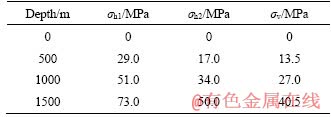
To investigate the influence of depth on induced spalling in hard rock tunnels, the failure process of the rock surrounding four tunnels at different depths (0, 500, 1000 and 1500 m, where 0 m is a control group) was simulated experimentally. A TRW-3000 large-size rock true-triaxial electrohydraulic servo testing system (see Figures 2(a)-(d)) was used to perform true-triaxial compression tests on cubic specimens with a prefabricated circular hole. During the tests, the sidewall failure process of the specimens was monitored and recorded in real-time by monitoring equipment specially developed in-house (see Figures 2(e) and (f)). The true-triaxial test system and monitoring equipment have been described in detail by GONG et al [33], so this information will not be restated here. According to the calculation method of in situ stress used by GONG et al [33], the in situ stresses (vertical principal stress (��v), maximum horizontal principal stress (��h1) and minimum horizontal stress (��h2)) at the three depths (500, 1000 and 1500 m) were obtained, and the in situ stress of the 0 m specimen is set to 0 MPa. The in situ stress at four depths is presented in Table 1.
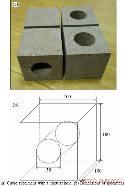
Figure 1 Experimental specimens:(Unit: mm)
For a certain geostress environment, the tunnel can be excavated in any horizontal direction. However, spalling and rockburst are affected by the lateral stress and axial stress, but the lateral stress is more obvious, and the smaller the lateral stress, the more severe the failure [33]. This indicates that the greater the difference of the two principal stresses in the tunnel cross-section, the more severe the tunnel failure. Therefore, in this study, a series of simulation experiments were performed on the most serious case of tunnel failure (i.e., the tunnel excavation direction is parallel to the direction of the maximum horizontal principal stress, as shown in Figure 3) to investigate the influence of depth on tunnel-induced spalling. The initial in situ stress of the four depth tunnels is shown in Figure 4.
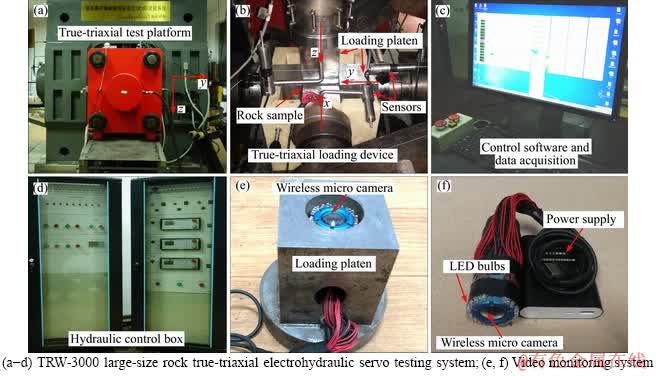
Figure 2 Testing equipment [33]:
Table 1 In situ stress at four depths
After hard rock tunnel excavation, stress redistribution leads to the formation of a stress concentration in the rock around the tunnel. When the induced stress exceeds the strength of the surrounding rock, the instability is primarily associated to the rock spalling or rockburst. Generally, spalling and rockburst are local failure of hard rock tunnels, i.e., the overall instability of the tunnel does not occur after spalling or rockburst. Therefore, the overall failure of the specimens should be prevented as much as possible during the test. To better simulate the process of induced spalling in hard rock tunnels, the stress loading path proposed by GONG et al [33] was used in the experiment, as shown in Figure 5.
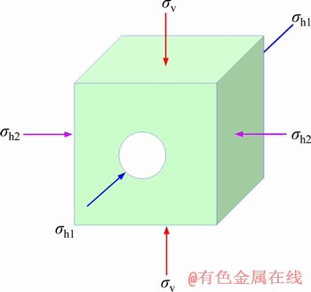
Figure 3 Schematic illustration of tunnel arrangements
3 Test results and analysis
3.1 Stress path and failure mode
As shown in Figure 6, the specimen at 0 m is loaded only in the vertical direction (z), and the other three specimens (500, 1000 and 1500 m) are loaded in all three directions (x, y and z). As the horizontal principal stresses are 0 MPa, overall failure occurred in a short period in the specimen at 0 m after a small amount of rock fragments ejection appeared on both sidewalls (see Figure 7(a)), so the loading curve has no step loading and a sudden stress drop occurs in the continuous loading stage. The other three specimens are affected by the horizontal principal stresses owing to the increase in depth; all of them are loaded by step loading after the obvious spalling occurs in both sidewalls. Although the occurrence of serious failure was observed along the sidewalls of these three specimens, they do not undergo overall failure (see Figures 7(b)-(d)). In addition, as the depth increases, the initial stress threshold of the step loading and the maximum vertical stress of the specimens are significantly increased. For example, the specimen at 0 m failed to enter the step loading stage even though overall failure occurred (peak of ��z is 39.8 MPa), and the initial stress threshold of the step loading and the maximum vertical stress of the other three specimens are 55, 73 and 99 MPa and 70, 95 and 112 MPa, respectively. This indicates that as the depth increases, the stress required for the sidewall initial failure and the bearing capacity of the hard rock tunnel increases.
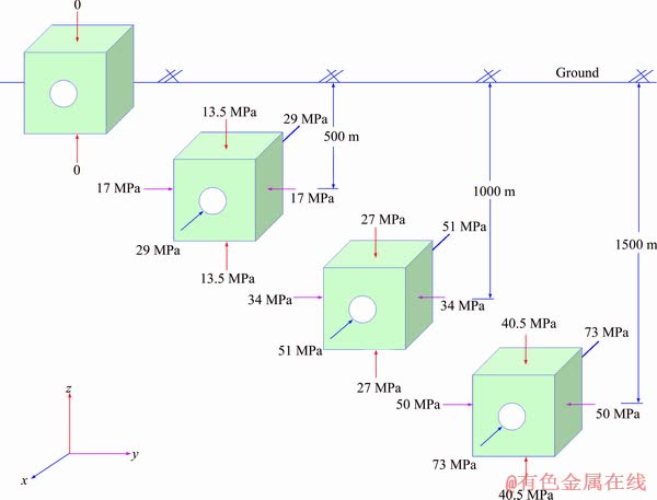
Figure 4 In situ stress of four depth tunnels
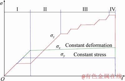
Figure 5 Schematic illustration of loading path (I: Initial loading; II: Continuous loading; III: Step loading; IV: Constant loading) [33]
Figure 7 presents the overall and local failure of four specimens after the experiment. As shown, the failure zones, with different severity, are formed on both sidewalls of the four specimens, and the locations of the failure zones of each specimen are basically symmetrical and in the middle of the sidewall. Four specimens all exhibit that the width of the failure zones gradually decreases as the distance to the holes increases, and the shape of the failure zones exhibits a ��V�� shape (i.e., V-shaped notch). For the specimen at 0 m, due to the absence of the horizontal principal stresses, a small amount of rock fragments ejection occurred at the sidewalls under the low stress level, followed by the overall failure of the specimen and the formation of several macroscopic shear cracks, running through the top and bottom, the top and sidewall and the bottom and sidewall. A small amount of rock fragments accumulated at the bottom of the hole, and the fragments are small; the depth and width of the failure zones on both sidewalls are shallow and narrow, respectively (see Figure 7(a)). The specimen at 500 m did not undergo overall failure, but a shear crack running through the top and sidewall is produced on the right side of the specimen surface. Two obvious V-shaped notches form on the sidewalls owing to the occurrence of the rock fragments flaking and ejection, and the width and depth of the V-shaped notches are significantly greater than those of the specimen at 0 m. As a result, more rock fragments are produced, and the fragments are also larger than those of the specimen at 0 m. On the right sidewall, some obvious buckling rock slabs (i.e., spalling) form (see Figure 7(b)). Overall failure of the specimen at 1000 m did not occur, but there is a considerable difference in the failure on either sidewall; some rock fragments formed, serious flaking and ejection occurred, and an obvious V-shaped notch formed on the right sidewall. In addition, a long tensile crack located on the upper side of the V-shaped notch runs through nearly the entire axial length of the hole. On the left sidewall, slight spalling appeared only in a small area (the failure zone on the right sidewall has extended through the axial length of the hole, and serious failure occurred; to prevent the sudden overall failure of the specimen, no further loading was applied), and no obvious flaking or ejection of rock fragments occurred. Therefore, the difference in failure between the sidewalls is very significant, which may be caused by the loading set-up and specimen processing precision. Although obvious rock fragments flaking and ejection occurred only on one sidewall, a large number of rock fragments accumulated at the bottom of the hole owing to the serious spalling and rockburst failure that occurred on the right sidewall, and the rock fragments were relatively large (see Figure 7(c)). At high loading stress level of the specimen at 1500 m, extremely serious spalling and rockburst failure occurred on both sidewalls, but the specimen did not undergo overall failure. A large number of large rock fragments accumulated at the bottom of the hole, and the width and depth of the V-shaped notches on both sidewalls are respectively wide and deep, but no cracks that run through the overall specimen formed. On the left and right sidewalls, respectively, the formation of large rock slabs will cause instability (see Figure 7(d)).
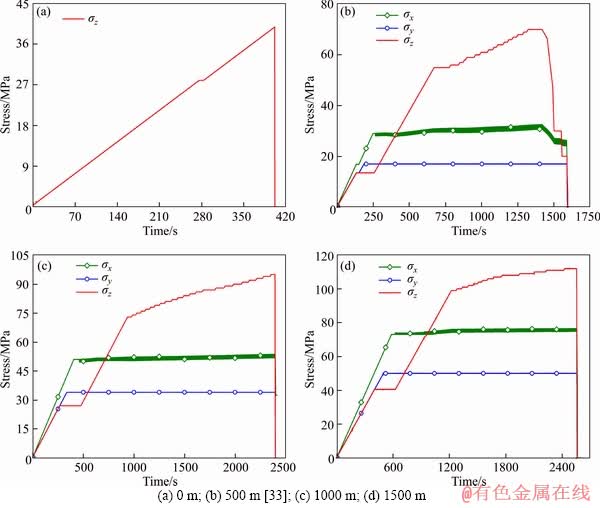
Figure 6 Loading paths of tests:
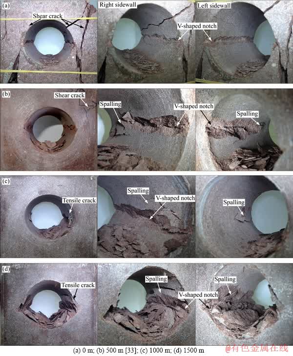
Figure 7 Failure mode of specimens representing different depths:
Therefore, as the depth increases, hard rock tunnel primarily undergoes tensile failure, the tensile cracks extend along the direction of the approximately parallel excavation surface, and the spalling became more intense; the stress required for the initial failure of the tunnels clearly increased, the size and mass of the rock fragments and depth and width of the V-shaped notches increased, and the range of the failure zone gradually develops from the local area to the entire periphery of the tunnel; the support area around the tunnel should be increased to prevent spalling.
Figure 8 shows the field failure of the sidewall in hard rock tunnel and raise. As shown, symmetrical V-shaped notches formed on both sidewalls in the direction perpendicular to the maximum principal stress. At the end of the experiments in this study, the four specimens also formed symmetrical V-shaped notches on both sidewalls perpendicular to the direction of the vertical principal stress (��z), and the geometry and location of the failure zones in the experiments are very similar to those observed in the field failure of the hard rock tunnel and raise. Therefore, to a certain extent, the experimental simulation in this study can effectively reflect the process of induced spalling in hard rock tunnels.
3.2 Failure process of induced spalling
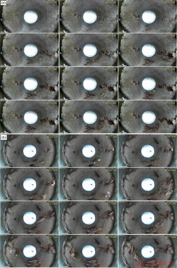
During the experiment, monitoring equipment specially developed in-house was used to record the whole failure process of the sidewall. By stopping the video of the failure process of the holes at different times (only part of the obvious failure was captured), the process of induced spalling of the holes at different depths was obtained, as shown in Figure 9. As shown, the failure processes along the sidewalls of the four specimens before the overall failure occurs are basically similar and can be described as follows. At the early stage of failure, the sidewall begins to undergo failure at the location of the maximum tangential stress (midpoint of the sidewall); this failure is primarily the rapid ejection of small rock fragments and particles, which fly from the sidewall to the open space of the hole at a certain initial velocity (capturing a clear picture with the mini-camera is difficult owing to the influence of the small size and the background colour of the hole, so these failure pictures are not captured, but this process can be observed from the dynamic process of video playback). Because the red sandstone is hard, it is difficult to observe obvious deformation of the sidewalls before failure. As the vertical principal stress (��z) increases, the cracks around the hole propagate farther and coalesce to form rock slabs (i.e., spalling) approximately parallel to the hole surface, and then the rock slabs flake or suddenly broke to cause rock fragments ejection (i.e., rockburst). At this stage, an obvious failure zone formed along the sidewalls, buckling deformation of the rock slabs was observed, and the size of the rock fragments increased. At each timestep, a large number of rock fragments were ejected; although there will be a quiet period, obvious rock fragments ejection will occur again only after the vertical stress is increased to a higher stress level, so rockburst occurs intermittently as the vertical principal stress increases. During the failure process, rock slabs on both sidewalls developed discontinuously, layer by layer, from the exposed surface to the inside of the rock, and the rock fragments flaked or ejected continuously to form a V-shaped notch on both sidewalls. The geometry of the V-shaped notch changes constantly with the development of the sidewall failure: the width and depth of the V-shaped notch increase. However, there are some differences in the failure process of specimens at different depths. As the depth increases, the size of rock fragments produced by spalling and the rock fragment mass of each ejection or flaking event increase, and the failure becomes more intense. This indicates that the geometrical characteristics and severity of spalling in hard rock tunnels are significantly affected by the depth.
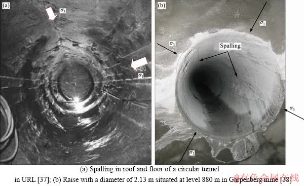
Figure 8 Field failure mode of sidewall in hard rock tunnel and raise:
to be continued
continued
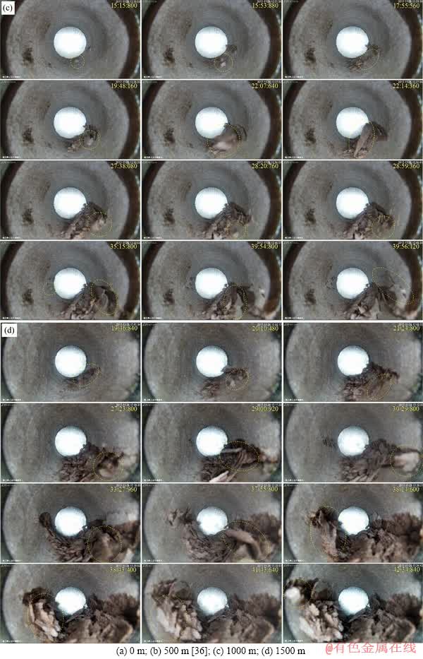
Figure 9 Failure process along sidewalls of specimens representing different depths (digits in the picture are time, min:s:ms):
3.3 Stress characteristics of sidewalls initial failure
Using the loading data (load-time curve) collected and the failure videos of the sidewall recorded by the mini-camera during the experiment, the loading stress states corresponding to the failure of the sidewalls at any moment can be obtained. To analyse the stress of a sidewall initial failure at different depths, first observe the video recorded to determine the timing of the sidewall initial failure, and then obtain the stress corresponding to the timing of the sidewall initial failure by the load-time curve. According to the method described above, the vertical principal stress of the sidewall initial failure (��zi), the tangential stress of the sidewall initial failure (����i) (assuming that the rock mass can be regarded as an elastic body before its failure, so ����i=3��zi-��y, where ��y is the stress in the y direction) can be obtained and are listed in Table 2.
Table 2 Stress characteristics of sidewalls initial failure at different depths
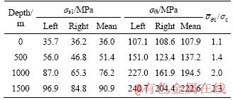
Figure 10 presents the variation of the vertical principal stress and the tangential stress required for the sidewalls initial failure with the increase in depth. As shown in Figure 10(a), as the depth increases, the vertical principal stress required for the sidewalls initial failure increases, but there are some differences in the ��zi between the two sidewalls of the same specimen. For example, the stress difference in ��zi between the two sidewalls is small, 0.5 MPa, when the depth is 0 m. When the depths are 500 m, 1000 m and 1500 m, the stress differences in ��zi between the two sidewalls are large: 9.2, 21.7 and 12.1 MPa, respectively. This result may be caused by the influence of the loading set-up and sample processing precision. To obtain the relationship between ��zi and the depth, the mean value of ��zi was analysed along both sidewalls of the same specimen. The results show that there is a good linear relationship between
 and the depth of the specimens, exhibiting an increasing trend with the increase in the depth. For example, when the depth increases from 0 m to 1500 m, increases by 152.5%. Therefore, as the depth increases, the far-field maximum principal stress required for the sidewall initial failure of the tunnel gradually increases, i.e., the tunnel carrying capacity is enhanced.
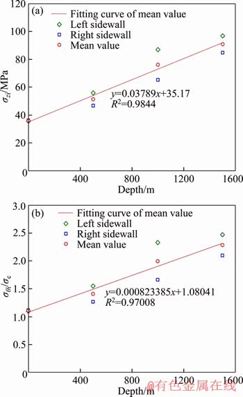
Figure 10 Stress characteristics of sidewalls initial failure at different depths
Figure 10(b) shows the relationship between the ����i/��c ratio and the depth. As shown, ����i/��c increases with the increase in the depth, the ratios of (
( is the mean value of ����i) of the four depths are 1.1, 1.4, 2.0 and 2.3, respectively, and exhibits a good linear relationship with the depth within a certain error range. Generally, spalling occurs when the ratio of the tangential stress to the strength reaches 0.4-0.5 in field tunnels [20]. In this paper, the ratios of ����i/��c at different depths are significantly greater than 0.4-0.5. The author believes that the main reasons for this result are as follows. 1) Since the experiment uses a reduced-scale tunnel model, the results are affected by the scale effect to some extent. MARTIN [39] performed uniaxial compression tests on 13 granite specimens with different hole diameters (from 5 mm to 103 mm) and found that the ����i/��c ratios are greater than 1 when the hole diameter is less than 75 mm. It is reported that this is attributed to the strength size effect; the smaller the diameter is, the more obvious the strength size effect is. In this study, when the depth is 0 m, the specimen is loaded in only the vertical direction, so the rocks around the hole have a unidirectional stress state and will be damaged when the tangential stress around the hole reaches its uniaxial compressive strength (i.e., ����i/��c=1). However, the test result of this study is ����i/��c>1 (hole diameter (F50 mm) is less than 75 mm), which is generally consistent with the results obtained by MARTIN [39]. 2) The difference in surrounding rock strength between the field tunnel and tunnel model. Practical experience indicates that the field strength of rock massive is approximately one half the laboratory strength [39], which results in test results greater than field results. 3) Due to the true-triaxial loading test performed in this paper (except for specimen with a depth of 0 m), the sidewall initial failure is affected by the axial stress. In general, the tunnel is simplified to a plane strain problem for mechanical analysis, considering only the two principal stresses in the plane of the tunnel cross-section and neglecting the influence of the stress in the axial direction of the tunnel. Therefore, in most cases, the rock around the tunnel is approximately considered to be in a unidirectional stress state. However, the experimental results in this study show that, as the
depth increases (i.e., axial stress increase), ����i/��c gradually increases and reaches 2.3 when the depth is 1500 m, which indicates that a large error arises when approximating the rock with a unidirectional stress state when the depth of the tunnel is deep. A large number of studies have shown that the intermediate principal stress (��2) will affect the rock strength [40-43]. Generally, it is believed that the rock strength increases gradually with the intermediate principal stress (��2) in the case of constant minimum principal stress (��3) [40]. Based on the strength criterion proposed by WANG et al [41], rock strength will increase at least 18%, 40% and 75% when ��2/��c=0.2, 0.5 and 1.0, respectively. The true-triaxial compression tests were performed on rocks by HAIMSON et al [42], who found that the rock strength increases by approximately 40%-50% when ��2/��c= 0.1 and ��3=0. MURRELL [43] noted that the rock strength will increase by 100% when ��2/��c=0.5 and ��3=0. Based on these studies, it can be concluded that the rock around the tunnel cannot be regarded as a unidirectional stress state, and the failure of the rock around the tunnel is affected by the axial stress. For the experiments in this study, the stress state of the rock around the holes is ��1=����i (��1 is the maximum principal stress), ��2=��x (i.e., axial stress) and ��3=0 when the sidewall initial failure occurs. Therefore, for the rock around the holes, the tangential stress required for its initial failure (i.e., spalling strength) is mainly affected by the corresponding axial stress. When the depth is 500 m (��2/��c=0.3), spalling strength around the hole is increased by 40.7%. The spalling strength around the hole is increased by 99.5% when the depth is 1000 m (��2/��c=0.52), and the spalling strength around the hole is increased by 128.3% when the depth is 1500 m (��2/��c=0.75) (to facilitate the analysis, the mean value of the tangential stress ����i corresponding to the depth is used in the calculation, which does not consider the influence of the strength size effect). This indicates that the axial stress can improve the spalling strength of the rock around the tunnels within a certain stress range.
Therefore, we concluded that the far-field maximum principal stress and the tangential stress required for the initial failure of the rock around the tunnels increase with depth, and both exhibit a good linear relationship with the tunnel depth. The strength of the rock around the tunnels is affected by the axial stress, and the influence becomes increasingly significant as the depth increases. In engineering practice, the stability analysis and support design of deep hard rock tunnels should fully consider the influence of axial stress. Because the diameter of tunnels is generally much larger than 75 mm, the influence of the strength size effect on the surrounding rock is negligible, but the influence of the strength size effect should be considered for deep boreholes with diameters less than 75 mm.
3.4 Size characteristics of rock fragments
According to the analysis in Section 3.1, there is a significant difference in the rock fragments caused by spalling on the sidewalls of the specimens at different depths. To further analyse the influence of depth on the failure characteristics of the specimen sidewalls, the rock fragments of each specimen are screened. The rock fragments from the four specimens are screened by sieving with different mesh numbers to obtain the mass and the corresponding mass fraction in different particle size ranges, and the results are listed in Table 3.
Figure 11 presents the mass percentage distribution characteristics of the four specimens. As shown, when the rock fragment size is in the range of 0-0.5 mm, 0.5-1.18 mm and 1.18-2.36 mm, the rock fragment mass fraction of the 0 m specimen is greater than that of the other three specimens; generally, the greater the depth is, the smaller the mass fraction of the rock fragment. When the rock fragment size is in the range of 2.36-10 mm, 10-15 mm and >15 mm, the largest mass fraction of rock fragments is 500, 1000 and 1500 m, respectively. Therefore, the rock fragment size increased from 2.36-10 mm to 10-15 mm, and then increased to >15 mm, and the depth corresponding to the largest mass fraction of rock fragments in each size range gradually increases. When the sizes of the rock fragments increase to >15 mm, the greater the depth, the larger the corresponding rock fragment mass fraction, which is completely opposite to the results of the rock fragment sizes less than 2.36 mm. This indicates that spalling tends to produce smaller rock fragments when the depth of the tunnel is shallow, and as the depth increases, the spalling tends to produce larger rock fragments, resulting in an increase in the mass percentage of the larger rock fragments. Therefore, shallow tunnel spalling produces small rock fragments and narrow failure zones (see Figure 7(a)), while deep tunnel spalling tends to produce large rock fragments with wide failure zones (see Figure 7(d)). For shallow hard rock tunnels, only local areas around the tunnel need to be supported, while deep hard rock tunnels need to support the entire perimeter of the tunnel.
4 Test results and analysis
4.1 Validity of spalling test simulation process
As mentioned in Section 2.2, when the sidewall failure is obvious, the loading method in the z direction is changed from continuous loading to step loading to prevent the overall failure of the specimen during the experiment. Due to the influence of the different loading stress conditions, although the step loading method is adopted in the late stage of loading, it is still difficult to prevent the specimens from undergoing overall failure and to achieve good simulation results during the test. Therefore, there are two types of loading curves for this test, as shown in Figure 12. The first loading curve causes the overall failure of the specimen during the process of continuous loading, and a rapid stress drop appears on the loading curve (see Figure 12(a)), i.e., the overall failure of the specimen occurs before the test enters the stage of step loading. For example, the specimen at 0 m belongs to the case of Figure 12(a) (see Figure 6(a)). The second loading curve for the test includes the stage of step loading; obvious spalling occurs, a serious failure zone forms on both sidewalls under the action of high stress, and induced spalling in tunnels is effectively simulated. Therefore, artificial unload is performed at the end of the experiment, and the specimens of 500, 1000 and 1500 m belong to the case of Figure 12(b) (see Figures 6(b)-(d)).
Table 3 Size characteristics of rock fragments at different simulated depths
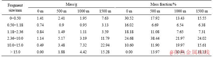
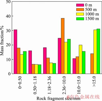
Figure 11 Size distribution characteristics of rock fragments at different depths
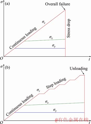
Figure 12 Two loading curves that may occur during true-triaxial test simulation of tunnel-induced spalling
According to field case analysis, MARTIN [3] noted that the geometry of the V-shaped notch will provide sufficient confinement to stop the failure at the notch tip after the V-shaped notch has reached a certain depth (see Figure 13(a)). DIEDERICHS [17] reported that the failure geometry is often a notch shaped and that the surrounding rock is self-stable after failure in the case of in situ stress ratios greater than or less than 1 (see Figure 13(b)). Therefore, the range of the failure zone caused by spalling or rockburst in a tunnel is limited, and the surrounding rock can maintain self-stability after failure is developed to a certain depth, without causing overall instability of the tunnel. In addition, spalling and rockburst is the process of dissipating and releasing elastic strain energy stored in a rock mass; that is, the energy required for its failure comes from internal rather than external energy or work (see Figure 13(c)). Therefore, during the test simulation of tunnel-induced spalling, the specimens should not undergo overall failure throughout the loading process (i.e., the loading curve should belong to the type shown in Figure 12(b)) to ensure that sidewall failure (flaking or ejection) is caused by the dissipation and release of the elastic strain energy stored in the specimen, to more accurately simulate the process of induced spalling in hard rock tunnels. For the specimen with a loading curve of the type shown in Figure 12(a), the occurrence of sidewall failure before specimen overall failure was caused by the dissipation and release of the elastic strain energy stored within the specimens. However, except for the elastic strain energy stored in the specimen, the energy required for rock fragments ejection caused by the specimen overall failure is mostly provided by the work done by the test machine when the stress suddenly drops. This process is not consistent with the process of induced rockburst in field hard rock tunnels. For example, Figure 14 shows the extremely intense ejection of rock fragments caused by the overall failure of the 0 m specimen. As shown, only a small amount of rock fragments is ejected before specimen overall failure occurs, owing to the release of the elastic strain energy stored in the specimen (see Figure 14(a)). At the moment of specimen overall failure, a large amount of rock fragments from both sidewalls suddenly spurt (the energy required primarily comes from the testing machine doing work) and instantly fill the entire hole space (see Figures 14(b)-(e)). Finally, three macro-cracks that run through the entire specimen formed on the sidewalls (see Figure 14(f)). Therefore, the rock fragments ejection process shown in Figures 14(b)-(f) cannot realistically simulate the process of induced rockburst of tunnels and is ineffective.
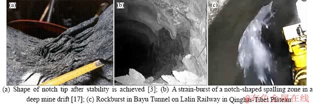
Figure 13 Spalling and rockburst in hard rock tunnel:
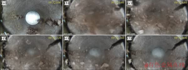
Figure 14 Overall instability process of 0 m specimen
Therefore, in the relevant experimental simulation investigation of spalling or rockburst in hard rock tunnels, it should be ensured that the specimen does not undergo overall failure and only local failure occurs, so the test results are effective, i.e., the sudden drop of stress can not occur on the stress path curve (except for artificial unloading), otherwise the test results are invalid.
4.2 Rationality of loading path of ��loading after excavation��
As we all know, the excavation of underground tunnel or caverns will have an unloading effect on the surrounding rock. Currently, in the indoor tunnel test simulation, it is difficult to achieve the unloading process by drill a hole in rock specimen under true-triaxial loading conditions to consider the influence of the excavation unloading effect on the surrounding rock. Therefore, the loading path of ��loading after excavation�� is primarily used in physical model testing of tunnels in the laboratory [25-28, 44, 45], i.e., first drill a hole in the specimen and then loading the specimen.
At present, there are two kinds of excavation methods in hard rock tunnels, i.e., the tunnel boring machine (TBM) and the drill-blasting methods. Different excavation methods have different unloading rates for the rock around the tunnel. In general, unloading time of the drill-blasting method is in milliseconds (ms), while the unloading time of the TBM method is in seconds (s). LU et al [46] and YAN et al [47] performed in-depth studies of the surrounding rock damage and rockburst caused by these two excavation methods. It is reported that the strain rate caused by the unloading with the TBM method is less than 10-1/s, the surrounding rock is relatively stable, and the unloading effect caused by excavation has little influence on the rockburst. The strain rate caused by unloading with the drill-blasting method is greater than 10-1/s and is transient dynamic unloading, and the unloading effect produced has a greater effect on the surrounding rock damage. It is also noted that the blasting disturbance is not the decisive factor of the occurrence of rockburst but only a triggering factor. HE et al [48] performed strain rockburst tests on cubic sandstone specimens with a prefabricated circular hole using a ��step loading + disturbance�� loading method. It was found that when the step loading stress (i.e., static stress) is lower than a certain threshold, the applied disturbance will not cause rock failure; only when the step loading stress increases to a certain level will the applied disturbance induce the occurrence of rock fragment ejection. This result indicates that static loading is the dominant factor inducing rockburst. In addition, the case analysis of on-site rockburst shows that the vast majority of rockbursts occurred during the process of stress adjustment after tunnel excavation. For example, JIANG et al [49] and YAN et al [47] performed a statistical analysis of the rockburst occurrence time of the pilot tunnels at the Jinping II Hydropower Station. The results indicate that the peak period of rockburst occurred within a few hours after tunnel excavation, usually within 20 h (see Figure 15(a)). Currently, it has been a long time since unloading due to machinery or blasting excavation, and the rock around the tunnel is in a quasi-static stress field. Meanwhile, YAN et al [47] also performed a statistical analysis on the distance from the location of the rockburst to the tunnel face of the pilot tunnels at the Jinping II Hydropower Station; the results indicate that the majority of rockbursts occurred in the range of 6-12 m away from the tunnel face (see Figure 15(b)) and that this trend is similar to those of rockburst in other rock engineering applications. CHEN et al [50] analysed the occurrence time of rockburst and noted that rockburst generally lagged more than 6 h after tunnel excavation and that the distance from the location of the rockburst to the tunnel face was generally greater than 5 m. In addition, field engineering practices have indicated that the location of spalling generally lags behind the tunnel face by a certain distance [51, 52]. Therefore, most of the spalling and rockburst occurred primarily owing to the static stress loading of the surrounding rock caused by the stress redistribution when the tunnel face advanced, and the unloading effect due to excavation is not the main reason for spalling and rockburst.
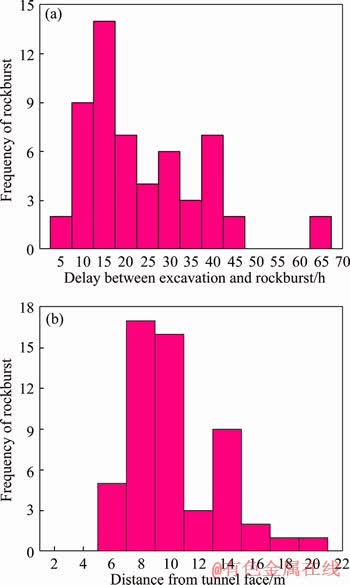
Figure 15 Time (a) and spatial (b) distribution of rockburst in pilot tunnels of Jinping II Hydropower Station [47, 49]
In this study, the test successfully reproduces the process of the rock fragments flaking and ejection in tunnels under the condition of considering the three-dimensional unbalanced static stress loading only, also exhibiting that the static stress is the dominant factor of spalling and rockburst. Therefore, within a certain error range, it is reasonable to use the loading path of ��loading after excavation�� to simulate spalling or rockburst in tunnels. Certainly, in future research, we will look for the test method that can realize ��loading before excavation�� under true-triaxial loading conditions, to perform the experimental investigation of tunnel-induced spalling under the conditions of considering the excavation unloading and static stress adjustment process.
5 Conclusions
A series of true-triaxial compression tests were performed on red sandstone cubic specimens with a prefabricated circular hole to investigate the influence of depth on induced spalling in hard rock tunnels, and the monitoring equipment that was specially developed in-house was used to monitor and record the process of induced spalling along the hole sidewalls in real-time. The process of induced spalling in hard rock tunnels at different depths was reproduced, and the validity of the test loading process, the rationality of the test loading method and the test results were systematically analysed and discussed. The main conclusions are as follows.
1) Spalling of the rocks around hard rock tunnels is affected by the depth, and the greater the depth, the more significant the impact. As the depth increases, hard rock tunnel primarily undergoes tensile failure, the tensile cracks extend along the direction of the approximately parallel tunnel surface, and the spalling becomes more intense; the size and mass of the rock fragments increase, and the range of the failure zone gradually develops from the local area to the entire periphery of the tunnel. Therefore, the tunnel support area should be increased accordingly to prevent spalling as the depth increases.
2) The far-field principal stress and tangential stress required for the initial failure of a tunnel both increase with depth, and both exhibit a good positive linear correlation with depth. As the depth increases, the axial stress of the tunnel exhibits an increasingly significant influence on spalling. Therefore, the stability analysis and support design of deep hard rock tunnels should consider the influence of axial stress. In addition, for deep small diameter boreholes, the effects of strength size effect should be considered when evaluating their stability, especially for boreholes less than 75 mm in diameter.
3) The general evolution process of the sidewall failure of hard rock tunnels during the advancement of the tunnel face is obtained. When the tangential stress exceeds the strength of the rock around the tunnel, the early stage of sidewall failure primarily exhibits ejection of a few small particles. As the stress further increases, the cracks propagate along the direction approximately parallel to the tunnel surface to form buckling rock slabs (spalling). When the buckling rock slabs suddenly create instability, a large number of rock fragments are ejected to form rockburst, and a V-shaped bursting pit is formed on the sidewall.
4) For the indoor simulation test of tunnel induced spalling or rockburst, it should be ensured that the specimen is intact and only local failure occurs, so as to ensure that the rock failure is caused by the release of elastic strain energy stored inside the rock.
References
[1] LI Xi-bing, GONG Feng-qiang, TAO Ming, DONG Long-jun, DU Kun, MA Chun-de, ZHOU Zi-long, YIN Tu-bing. Failure mechanism and coupled static-dynamic loading theory in deep hard rock mining: A review [J]. Journal of Rock Mechanics and Geotechnical Engineering, 2017, 9(4): 767-782. DOI: 10.1016/j.jrmge.2017.04.004.
[2] XIE He-ping, GAO Ming-zhong, ZHANG Ru, PENG Gao-you, WANG Wen-yong, LI An-qiang. Study on the mechanical properties and mechanical response of coal mining at 1000 m or deeper [J]. Rock Mechanics and Rock Engineering, 2019, 52(5): 1475-1490. DOI: 10.1007/ s00603-018-1509-y.
[3] MARTIN C D. Seventeenth Canadian geotechnical colloquium: The effect of cohesion loss and stress path on brittle rock strength [J]. Canadian Geotechnique Journal, 1997, 34(5): 698-725. DOI: 10.1139/t97-030.
[4] ZHAO Xing-guang, CAI Ming. Influence of specimen height-to-width ratio on the rockburst characteristics of Tianhu granite under true-triaxial unloading conditions [J]. Canadian Geotechnique Journal, 2015, 52(7): 890-902. DOI: 10.1139/cgj-2014-0355.
[5] ZHOU Hui, MENG Fan-zhen, ZHANG Chuan-qing, HU Da-wei, YANG Fan-jie, LU Jing-jing. Analysis of rockburst mechanisms induced by structural planes in deep tunnels [J]. Bulletin of Engineering Geology and the Environment, 2015, 74(4): 1435-1451. DOI: 10.1007/s10064-014-0696-3.
[6] ZHOU Hui, LU Jing-jing, XU Rong-chao, ZHANG Chuan- qing, MENG Fan-zhen. Critical problems of study of slabbing failure of surrounding rock in deep hard rock tunnel and research progress [J]. Rock and Soil Mechanics, 2015, 36(10): 2737-2749. DOI: 10.16285/j.rsm.201 5.10.001. (in Chinese)
[7] ZHAO Xing-dong, ZHANG Hong-xun, ZHU Wan-cheng. Fracture evolution around pre-existing cylindrical cavities in brittle rocks under uniaxial compression [J]. Transactions of Nonferrous Metals Society of China, 2014, 24(3): 806-815. DOI: 10.1016/S1003-6326(14)63129-0.
[8] ZUO Yu-jun, LI Xi-bing, ZHOU Zi-long. Determination of ejection velocity of rock fragments during rock burst in consideration of damage [J]. Journal of Central South University, 2005, 12(5): 618-622. DOI: 10.1007/s11771- 005-0133-7.
[9] MITELMAN A, ELMO D. Analysis of tunnel support design to withstand spalling induced by blasting [J]. Tunnelling and Underground Space Technology, 2016, 51: 354-361. DOI: 10.1016/j.tust.2015.10.006.
[10] JIA Peng, ZHU Wan-cheng. Dynamic-static coupling analysis on rockburst mechanism in jointed rock mass [J]. Journal of Central South University, 2012, 19(11): 3285- 3290. DOI: 10.1007/s11771-012-1405-7.
[11] ZHANG Chuan-qing, FENG Xia-ting, ZHOU Hui, QIU Shi-li, WU Wen-ping. Case histories of four extremely intense rockbursts in deep tunnels [J]. Rock Mechanics and Rock Engineering, 2012, 45(3): 275-288. DOI: 10.1007/s00 603-011-0218-6.
[12] FENG Xia-ting, XU Hong, QIU Shi-li, LI Shao-jun, YANG Cheng-xiang, GUO Hao-sen, CHENG Yuan, GAO Yao-hui. In situ observation of rock spalling in the deep tunnels of the China Jinping underground laboratory (2400 m depth) [J]. Rock Mechanics and Rock Engineering, 2018, 51(4): 1193-1213. DOI: 10.1007/s00603-017-1387-8.
[13] TANG Li-zhong, XIA Kai-wen. Seismological method for prediction of areal rockbursts in deep mine with seismic source mechanism and unstable failure theory [J]. Journal of Central South University, 2010, 17(5): 947�C953. DOI: 10.1007/s11771-010-0582-5.
[14] GONG Feng-qiang, YAN Jing-yi, LI Xi-bing, LUO Song. A peak-strength strain energy storage index for rock burst proneness of rock materials [J]. International Journal of Rock Mechanics and Mining Sciences, 2019, 117: 76-89. DOI: 10.1016/j.ijrmms.2019.03.020.
[15] JIANG Bang-you, GU Shi-tan, WANG Lian-guo, ZHANG Guang-chao, LI Wen-shuai. Strainburst process of marble in tunnel-excavation-induced stress path considering intermediate principal stress [J]. Journal of Central South University, 2019, 26(4): 984-999. DOI: 10.1007/s11771- 019-4065-z.
[16] LI Tian-zheng, LI Yong-xin, YANG Xiao-li. Rock burst prediction based on genetic algorithms and extreme learning machine [J]. Journal of Central South University, 2017, 24(9): 2105-2113. DOI: 10.1007/s11771-017-3619-1.
[17] DIEDERICHS M S. The 2003 Canadian geotechnical colloquium: Mechanistic interpretation and practical application of damage and spalling prediction criteria for deep tunnelling [J]. Canadian Geotechnique Journal, 2007, 44(9): 1082-1116. DOI: 10.1139/T07-033.
[18] DYSKIN A V, GERMANOVICH L N. Model of rockburst caused by cracks growing near free surface [C]// Rockbursts and Seismicity in Mines. Balkema, Rotterdam, 1993: 169-174. https://eurekamag.com/research/023/047/ 023047419.php.
[19] DU Kun, TAO Ming, LI Xi-bing, ZHOU Jian. Experimental study of slabbing and rockburst induced by true-triaxial unloading and local dynamic disturbance [J]. Rock Mechanics and Rock Engineering, 2016, 49(9): 3437-3453. DOI: 10.1007/s00603-016-0990-4.
[20] SHEN Bao-tang, BARTON N. Rock fracturing mechanisms around underground openings [J]. Geomechanics and Engineering, 2018, 16(1): 35-47. DOI: 10.12989/gae.2018. 16.1.035.
[21] GONG Qiu-ming, YIN Li-jun, WU Shi-yong, ZHAO Jian, TING Yi-lee. Rock burst and slabbing failure and its influence on TBM excavation at headrace tunnels in Jinping II hydropower station [J]. Engineering Geology, 2012, 124: 98-108. DOI: 10.1016/j.enggeo.2011.10.007.
[22] HIDALGO K P, NORDLUND E. Failure process analysis of spalling failure��Comparison of laboratory test and numerical modelling data [J]. Tunnelling and Underground Space Technology, 2012, 32: 66-77. DOI: 10.1016/j.tust. 2012.05.005.
[23] SU Guo-shao, JIANG Jian-qing, ZHAI Shao-bin, ZHANG Gang-liang. Influence of tunnel axis stress on strainburst: An experimental study [J]. Rock Mechanics and Rock Engineering, 2017, 50(6): 1551-1567. DOI: 10.1007/ s00603-017-1181-7.
[24] QIU Shi-Li, FENG Xia-ting, ZHANG Chuan-qing, XIANG Tian-bing. Estimation of rockburst wall-rock velocity invoked by slab flexure sources in deep tunnels [J]. Canadian Geotechnique Journal, 2014, 51(5): 520-539. DOI: 10.1139/cgj-2013-0337.
[25] HE Man-chao, LIU Dong-qiao, GONG Wei-li, WANG Cheng-chao, KONG Jie, DU Shuai, ZHANG Shen. Development of a testing system for impact rockbursts [J]. Chinese Journal of Rock Mechanics and Engineering 2014, 39(9): 1729-1739. DOI: 10.13722/j.cnki.jrme. 2014.09.001. (in Chinese)
[26] KUSUI A, VILLAESCUSA E, FUNATSU T. Mechanical behaviour of scaled-down unsupported tunnel walls in hard rock under high stress [J]. Tunnelling and Underground Space Technology. 2016, 60: 30-40. DOI: 10.1016/j.tust. 2016.07.012
[27] KUSUI A, VILLAESCUSA E. Seismic response prior to spalling failure in highly stressed underground tunnels [C]// Proceedings of the Seventh International Conference and Exhibition on Mass Mining. Sydney, Australia, 2016. https://www.researchgate.net/publication/303495024.
[28] VILLAESCUSA E, KUSUI A. Evaluating the performance of high energy dissipation capacity surface support systems [C]// Proceedings of International Symposium on Earth Science and Technology. Kyushu, Japan, 2018. https://www. researchgate.net/publication/329826685.
[29] MARTIN C D, KAISER P K, MCCREATH D R. Hoek-brown parameters for predicting the depth of brittle failure around tunnels [J]. Canadian Geotechnique Journal, 1999, 36(1): 136-151. DOI: 10.1139/t98-072.
[30] ZHU Wan-cheng, LI Zhan-hai, ZHU Li-kai, TANG Chun-an. Numerical simulation on rockburst of underground opening triggered by dynamic disturbance [J]. Tunnelling and Underground Space Technology, 2010, 25(5): 587-599. DOI: 10.1016/j.tust.2010.04.004.
[31] MAZAIRA A, KONICEK P. Intense rockburst impacts in deep underground constructions and their prevention [J]. Canadian Geotechnique Journal, 2015, 52(10): 1426-1439. DOI: 10.1139/cgj-2014-0359.
[32] KAISER P K, CAI M. Design of rock support system under rockburst condition [J]. Journal of Rock Mechanics and Geotechnical Engineering, 2012, 4(3): 215-227. DOI: 10.3724/SP.J.1235.2012.00215.
[33] GONG Feng-qiang, LUO Yong, LI Xi-bing, SI Xue-feng, TAO Ming. Experimental simulation investigation on rockburst induced by spalling failure in deep circular tunnels [J]. Tunnelling and Underground Space Technology, 2018, 81: 413-427. DOI: 10.1016/j.tust.2018.07.035.
[34] GONG Feng-qiang, SI Xue-feng, LI Xi-bing, WANG Shan-yong. Experimental investigation of strain rockburst in circular caverns under deep three-dimensional high-stress conditions [J]. Rock Mechanics and Rock Engineering, 2019, 52(5): 1459-1474. DOI: 10.1007/s00603-018-1660-5.
[35] GONG Feng-qiang, WU Wu-xing, LI Tian-bin, SI Xue-feng. Experimental simulation and investigation of spalling failure of rectangular tunnel under different three-dimensional stress states [J]. International Journal of Rock Mechanics and Mining Sciences, 2019, 122: 104081. DOI: 10.1016/j.ijrmms. 2019.104081.
[36] LUO Yong, GONG Feng-qiang, LIU Dong-qiao, Wang Shan-yong, SI Xue-feng. Experimental simulation analysis of the process and failure characteristics of spalling in D-shaped tunnels under true-triaxial loading conditions [J]. Tunnelling and Underground Space Technology, 2019, 90: 42-61. DOI: 10.1016/j.tust.2019.04.020.
[37] CHANDLER N. Developing tools for excavation design at Canada��s Underground Research Laboratory [J]. International Journal of Rock Mechanics and Mining Sciences, 2004, 41(8): 1229-1249. DOI: 10.1016/j.ijrmms. 2004.09.002.
[38] EDELBRO C. Numerical modelling of observed fallouts in hard rock masses using an instantaneous cohesion-softening friction-hardening model [J]. Tunnelling and Underground Space Technology, 2009, 24(4): 398-409. DOI: 10.1016/ j.tust.2008.11.004.
[39] MARTIN C D. Strength of massive Lac du Bonnet granite around underground openings [D]. Winnipeg: University of Manitoba, 1993. https://www.researchgate.net/publication/ 35053164.
[40] CAI Ming. Influence of intermediate principal stress on rock fracturing and strength near excavation boundaries�Cinsight from numerical modeling [J]. International Journal of Rock Mechanics and Mining Sciences, 2008, 45(5): 763-772. DOI: 10.1016/j.ijrmms.2007.07.026.
[41] WANG R, KEMENY J M. A new empirical failure criterion for rock under polyaxial compressive stresses [C]// Proceedings of the 35th US rock mechanics symposium. Balkema, Rotterdam, 1995: 453-482. https://www.onepetro. org/conference-paper/ARMA-95-0453
[42] HAIMSON B, CHANG C. A new true triaxial cell for testing mechanical properties of rock, and its use to determine rock strength and deformability of Westerly granite [J]. International Journal of Rock Mechanics and Mining Sciences, 2000, 37(1, 2): 285-296. DOI: 10.1016/S1365- 1609(99)00106-9.
[43] MURRELL S A F. A criterion for brittle fracture of rocks and concrete under triaxial stress and the effect of pore pressure on the criterion [C]// Proceedings of the fifth US rock mechanics symposium. 1963: 563-577. https://www. researchgate.net/publication/290486280.
[44] CHEON D S, JEON S, PARK C, SONG W K, PARK E S. Characterization of brittle failure using physical model experiments under polyaxial stress conditions [J]. International Journal of Rock Mechanics and Mining Sciences, 2011, 48(1): 152-160. DOI: 10.1016/j.ijrmms. 2010.10.001.
[45] LI Tian-bin, WANG Xiang-feng, MENG Lu-bo. A physical simulation test for the rockburst in tunnels [J]. Journal of Mountain Science, 2011, 8(2): 278-285. DOI: 10.1007/ s1162 9-011-2116-5.
[46] LU Wen-bo, ZHOU Chuang-bing, CHEN Ming, JIN Li,YAN Peng. Research on transient characteristics of excavation unloading [J]. Chinese Journal of Rock Mechanics and Engineering, 2008, 27(11): 2184-2192. http://www.rockmec h.org/CN/Y2008/V27/I11/2184. (in Chinese)
[47] YAN Peng, ZHAO Zhen-guo, LU Wen-bo, FAN Yong, CHEN Xiangrong, SHAN Zhi-gang. Mitigation of rock burst events by blasting techniques during deep-tunnel excavation [J]. Engineering Geology, 2015, 188: 126-136. DOI: 10.1016/j.enggeo.2015.01.011.
[48] HE Man-chao, XIA Hong-man, JIA Xue-na, GONG Wei-li, ZHAO Fei, LIANG Kang-yuan. Studies on classification, criteria and control of rockbursts [J]. Journal of Rock Mechanics and Geotechnical Engineering, 2012, 4(2): 97-114. DOI: 10.3724/SP.J.1235.2012.00097.
[49] JIANG Quan, FENG Xia-ting, XIANG Tian-bing, SU Guo-shao. Rockburst characteristics and numerical simulation based on a new energy index: A case study of a tunnel at 2500 m depth [J]. Bulletin of Engineering Geology and the Environment, 2010, 69(3): 381-388. DOI: 10.1007/ s10064-010-0275-1.
[50] CHEN Bing-rui, FENG Xia-ting, MING Hua-jun, ZHOU Hui, ZENG Xiong-hui, FENG Guang-liang, XIAO Ya-xun. Evolution law and mechanism of rockburst in deep tunnel: Time-delayed rockburst [J]. Chinese Journal of Rock Mechanics and Engineering, 2012, 31(3): 561-569. http:// www.rockmech.org/CN/Y2012/V31/I3/561. (in Chinese)
[51] MARTIN C D, READ R S, MARTINO J B. Observations of brittle failure around a circular test tunnel [J]. International Journal of Rock Mechanics and Mining Sciences, 1997, 34(7): 1065-1073. DOI: 10.1016/S1365-1609(97)90200-8.
[52] JIANG Quan, FENG Xia-ting, FAN Yi-lin, FAN Qi-xiang, LIU Guo-feng, PEI Shu-feng, DUAN Shu-qian. In situ experimental investigation of basalt spalling in a large underground powerhouse cavern [J]. Tunnelling and Underground Space Technology, 2017, 68: 82-94. DOI: 10.1016/j.tust.2017.05.020.
(Edited by FANG Jing-hua)
���ĵ���
�����Բ��Ӳ�����������ƻ�����Ӱ���ģ������
ժҪ��Ϊ���о������Բ�������շ������ƻ���Ӱ�죬�Ժ�Բ�ο����������ɰ������������һϵ�е�������ѹ�����飬���������Ƶ�����Ƶ����豸�Կ������ƻ����̽�����ʵʱ���ͼ�¼���õ��˲�ͬ��ʼ����(500��1000��1500 m)Բ����������ֱӦ�����������ж����ƻ������ݻ����̡�������������������ڷ���Ӧ�����ұ�֮ǰ�����γ��˰����ƻ����������γ�V-�Ͳۡ�������ʼ�ƻ������Զ����Ӧ���������������ء�������ȵ����ӣ��������ڳ�ʼ�ƻ������Ӧ�������������ƻ����Խ���ң���Ƭ�ijߴ��������V-�Ͳ۵���ȺͿ��Ⱦ������ƻ����ķ�Χ�����������ھֲ��������������ڡ���ˣ�������ȵ����ӣ�����֧������Ӧ��Ӧ�����Է�ֹ�����ƻ��ķ�����
�ؼ��ʣ�����¹��̣�Բ�������������ƻ���Ӧ�����ұ�����������أ�V-�Ͳ�
Foundation item: Projects(41877272, 41472269) supported by the National Natural Science Foundation of China; Project(2017zzts167) supported by the Fundamental Research Funds for the Central Universities, China
Received date: 2019-01-30; Accepted date: 2019-10-25
Corresponding author: GONG Feng-qiang, PhD, Professor; Tel: +86-18175973819; E-mail: fengqiangg@126.com; ORCID: 0000-0002- 2040-4294

