����CaO��Y��ZK40þ�Ͻ�ĸ�ʴ��Ϊ
��Դ�ڿ����й���ɫ����ѧ��(Ӣ�İ�)2018���3��
�������ߣ�Ricardo Henrique BUZOLIN Marta MOHEDANO Chamini Lakshi MENDIS Beatriz MINGO Domonkos TOLNAI Carsten BLAWERT Karl Ulrich KAINER Haroldo PINTO Norbert HORT
����ҳ�룺427 - 439
�ؼ��ʣ�þ�Ͻ�ZK40��Y���ӣ�CaO���ӣ���ʴ��Ϊ
Key words��Mg alloy; ZK40; Y addition; CaO addition; corrosion behaviour
ժ Ҫ���о������� ZK40������2% (��������)CaO������1% (��������)Y ��ZK40 þ�Ͻ������֯���������˽����仯���������ò�ͷֲ�������ZK40���紦��ɢ�Ľ����仯�����������������CaO��Y��ZK40������֯����Ϊ�ؾ���ֲ��Ľ����仯����İ���������ṹ������֯��û�м�CaO�� Ca ����������������γɵĽ����仯����Ca2Mg6Zn3�С�����͵绯ѧ�����迹������ʾ������CaO��Ͻ������������ߣ�������Y ȴ��ZK40����ʴ���и���Ӱ�졣������������ʾ�����صľֲ���ʴ���ؽ����仯����ĸ�ʴ��ZK40-Y�Ͻ�ĸ�ʴ��������ҪӰ�죬��ZK40 ��ZK40-CaO �Ͻ�ľֲ���ʴ�����ԡ�ZK40�Ͻ��Ц�-Mg �����е���ƫ�����Ը��ڼ�CaO��Y��ZK40�Ͻ��������ý�ϺϽ�����γ��˸����ȶ�����ʴ����ZK40-CaO�Ͻ����ʴ������ߵ���Ҫԭ��
Abstract: The microstructures of as-cast ZK40, ZK40 with 2% (mass fraction) CaO and ZK40 with 1% (mass fraction) Y were investigated, and the intermetallic phase morphology and the distribution were characterised. By having discrete intermetallic particles at the grain boundaries for the ZK40, the microstructure was modified to a semi-continuous network of intermetallic compounds along the grain boundaries for the ZK40 with CaO or Y additions. The CaO was not found in the microstructure. However, Ca was present in Ca2Mg6Zn3 intermetallic compounds which were formed during casting. Hydrogen evolution and electrochemical impedance spectroscopy tests revealed that the addition of CaO slightly enhanced the corrosion resistance whereas Y had a negative effect on the corrosion resistance of ZK40. Immersion tests showed that severe localised corrosion as well as corrosion along the intermetallic compounds played an important role in the corrosion process of ZK40-Y whereas the localised corrosion was not pronounced for ZK40 or ZK40-CaO alloys. Micro-segregation in the ��-Mg matrix was notably higher for the ZK40 alloy compared with the modified alloys. The combination of this effect with a possible formation of a more stable corrosion layer for the ZK40-CaO was attributed as the main reason for an improved corrosion resistance for the ZK40-CaO alloy.
Trans. Nonferrous Met. Soc. China 28(2018) 427-439
Ricardo Henrique BUZOLIN1,2, Marta MOHEDANO1,3, Chamini Lakshi MENDIS1,4, Beatriz MINGO3, Domonkos TOLNAI1, Carsten BLAWERT1, Karl Ulrich KAINER1, Haroldo PINTO5, Norbert HORT1
1. Magnesium Innovation Centre, Helmholtz-Zentrum Geesthacht, Max-Planck-Strasse 1, D 21502, Geesthacht, Germany;
2. Institute of Materials Science, Joining and Forming, Graz University of Technology, Kopernikusgasse 24/I, 8010 Graz, Austria;
3. Departamento de Ciencia de Materiales, Facultad de Ciencias  , Universidad Complutense, Av. Complutense, s/n, 28040 Madrid, Spain;
4. Brunel Centre for Advanced Solidification Technology, Brunel University London, Uxbridge, Middlesex, UB8 3PH, UK;
5. Department of Materials Engineering, University of Sao Paulo, Av. Joao Dagnone, 1100 Jd. Sta Angelina, 13563-120, Sao Carlos, Brazil
Received 15 February 2017; accepted 3 August 2017
Abstract: The microstructures of as-cast ZK40, ZK40 with 2% (mass fraction) CaO and ZK40 with 1% (mass fraction) Y were investigated, and the intermetallic phase morphology and the distribution were characterised. By having discrete intermetallic particles at the grain boundaries for the ZK40, the microstructure was modified to a semi-continuous network of intermetallic compounds along the grain boundaries for the ZK40 with CaO or Y additions. The CaO was not found in the microstructure. However, Ca was present in Ca2Mg6Zn3 intermetallic compounds which were formed during casting. Hydrogen evolution and electrochemical impedance spectroscopy tests revealed that the addition of CaO slightly enhanced the corrosion resistance whereas Y had a negative effect on the corrosion resistance of ZK40. Immersion tests showed that severe localised corrosion as well as corrosion along the intermetallic compounds played an important role in the corrosion process of ZK40-Y whereas the localised corrosion was not pronounced for ZK40 or ZK40-CaO alloys. Micro-segregation in the ��-Mg matrix was notably higher for the ZK40 alloy compared with the modified alloys. The combination of this effect with a possible formation of a more stable corrosion layer for the ZK40-CaO was attributed as the main reason for an improved corrosion resistance for the ZK40-CaO alloy.
Key words: Mg alloy; ZK40; Y addition; CaO addition; corrosion behaviour
1 Introduction
Mg alloys show potential use as lightweight structural materials, due to their satisfactory specific strength. However, one of the main obstacles that impede the use of Mg alloys [1] is the insufficient corrosion resistance in combination with an appropriate property profile.
Alloys based on the Mg-Zn system, such as ZK40, have the potential to be developed as low cost Mg alloys with high strength [2]. ZK (Mg-Zn-Zr) alloys are one of the highest strength commercially available alloys [3]. ZK60 has the highest strength among the ZK series and among most Mg alloys. However, its strength at room temperature and elevated temperature is lower than that of Al alloys. Recently, there have been numerous attempts to enhance the strength and ductility through the modification of alloy chemistry with the addition of quaternary and quinary alloying elements [4,5]. A commercial alloy based on the Mg-Zn system, ZE41 (Mg-4Zn-0.5Zr-1RE alloy) is used in the as-cast condition in the aerospace industry. Its corrosion behaviour was investigated [6,7] and the intermetallic phases in the ZE41 do not act as a corrosion barrier preventing the progress of the corrosion front as observed in the AZ (Mg-Al-Zn) alloys [8,9]. The ZK alloy system provides a potential pathway to develop novel alloys via the addition of quaternary alloying elements to ZE41.
The mechanical properties [10], microstructure modification [11], and texture randomisation [12,13] caused by Ca additions have been investigated previously. The addition of Ca to Mg-Zn alloys refines the grain size, contributes to solid solution hardening and enhances the precipitation hardening response [14,15]. Ca-containing Mg alloys [16] show similar increase in hardness and yield strength and weakened deformation texture achieved in Mg alloys containing RE. The addition of Ca to Mg is also attributed to an improved ignition resistance of Mg alloys [17]. WIESE et al [18] demonstrated that CaO reduces to form MgO and Mg2Ca during casting and solidification, which can provide an easier route to add Ca to Mg alloys. The formation of thermally stable intermetallic phases that stabilizes the microstructure during heat treatments and thermo- mechanical processes is of interest for applications at elevated temperatures [19]. Ca addition to ZK series alloys enhances creep resistance due to the refinement of the rod-like b1 and plate-like b2 precipitates [20]. The creep properties of the as-cast and heat-treated Mg-Zn-Ca alloys were enhanced both in tension [21] and compression [22]. Mg-Zn-Ca alloys also show promising applications as biodegradable implants [23,24] as both Zn and Ca are metabolized by the human body. Ca improves corrosion resistance of Mg alloys through the modification of the oxide layer [25]. JEONG and KIM [26] showed that for as-cast Mg-Ca alloys the increase of Ca additions significantly influences the anodic and cathodic polarisation to the detriment of the corrosion resistance. The corrosion behaviour of Mg-Zn-Ca has also been reported in Refs. [27,28]. BAKHSHESHI RAD et al [27] reported that the addition of Zn to the Mg-Ca-Zn system alloys improved corrosion resistance and LU et al [29] attributed the formation of galvanic corrosion as a major influence on the corrosion resistance of Mg-3Zn-0.3Ca alloys. The additions of Ca to Mg-Zn-Ca alloys seem to form adherent and insoluble corrosion products that are more stable than Mg(OH)2 [28].
The role of Y in Mg alloys has been studied extensively. The ratio of Y to Zn determines the microstructure and mechanical properties of Mg-Zn based alloys via the modification of intermetallic phases. A systematic investigation of the ternary Mg-Zn-Y phase diagram shows the presence of three equilibrium phases (W-phase, Mg3Zn3Y2; Z-phase, Mg3Zn6Y; and X-phase, Mg12ZnY) [30]. The W-phase has a structure similar to AlMnCu2, the Z-phase is identified as an icosahedral quasicrystalline phase and the X-phase is a long periodic structure with an 18R stacking sequence [30]. The X-phase transforms to 14H upon annealing [31,32]. Fine scaled LPSO (long period stacking ordered) structures are observed [33] when the ratio Y/Zn is large. Icosahedral phases containing Y and Zn are observed with intermediate ratios of Y/Zn [34-36]. The ratio between compressive and tensile yield strengths is closed to one unity in extruded alloys containing icosahedral phases [34], and the increased strength was attributed to the improved load transfer between the matrix and the intermetallic phase [37]. Enhanced tensile yield strength and ultimate tensile strength are observed with addition of Y to Mg-Zn alloys without significant loss in ductility [35]. The role of the microstructure on the corrosion behaviour of Mg-Y-RE-Zr alloys [38] shows that the Zr segregation within the grain was the main influence on corrosion resistance of these alloys and that the dissolution of the ��-Mg initiated between the grain centres and the grain boundary. Comparable corrosion behaviour was also reported by SONG et al [39] where filiform corrosion started in the central regions of the ��-Mg matrix in a T6 Mg-5.8Zn-0.9Y- 0.55Zr alloy.
However, more detailed investigations are needed in order to have a better understanding of the influence of Ca and Y additions on the corrosion behaviour of ZK alloys. In this work, the aim is to investigate the role of the microstructure features of as-cast ZK40 alloys produced with individual additions of CaO and Y on the corrosion resistance in naturally-aerated 0.5% (mass fraction) NaCl solution.
2 Experimental
2.1 Materials
Pure Mg, Zn, CaO and master alloys Mg-10%Y and Mg-33%Zr (Zirmax ) (mass fraction) were used to prepare the alloys used in the investigation. Molten Mg was held at 750 ��C in an electric resistance furnace under a protective atmosphere of Ar with 2% (volume fraction) SF6. At 750 ��C the alloying elements were added to the melt. Due to the protective atmosphere that is formed over the melt avoiding burning, a stirrer using a propeller with four blades was used to stir the melt for 10 min. This procedure aims to guarantee that the alloying additions are properly dissolved and well mixed in the melt before pouring. The melt was poured into a preheated thin-walled steel mould with a diameter of 10 cm and held at 660 ��C for 15 min and then the mould was immersed into water at a rate of 10 mm/s until the top of the melt was in line with the cooling water [40]. This casting procedure was adopted to provide a homogeneous microstructure. The actual compositions of the alloys were measured with a Brucker S5 X-ray fluorescence (Ca) and a Spectrolab spark analyser (Zn, Cu, Fe, Ni, Y and Zr).
2.2 Differential thermal analysis (DTA)
Differential thermal analysis (DTA) was conducted using a Mettler Toledo DTA model SDTA 851 under an Ar atmosphere in a steel crucible at heating and cooling rates of 10 K/min in the temperature range of 300-700 ��C. The heating and cooling cycles were repeated at least three times for each sample to ensure reproducibility of the measurement. In each cycle, the previous microstructure is destroyed due to melting of the material at temperature higher than 670 ��C and a new microstructure is formed during cooling.
2.3 Specimen preparation and characterisation
Specimens for metallographic characterisation were ground with SiC abrasive papers from P500 to P2500, followed by polishing with 3 ��m diamond suspension and then with a mixture of OPS and 1 ��m diamond suspension. The specimens used for optical microscopy (OM) were etched with an acetic picral solution [41], and imaged using a Leica DMI 5000 reflected light microscope. Grain size was determined according to the ASTM standard E112-12 using the linear intercept method. Scanning electron microscopy (SEM) was conducted on the unetched samples using a Carl Zeiss FEG-SEM Ultra 55 and a Tescan Vega3 SEM. Stereological measurements of the area fraction of intermetallic compounds were performed by using a minimum of 10 random BSE (backscattered electron) macrographs and analysing them using ImageJ software. The SEM was equipped with energy dispersive X-ray spectrometer (EDXS) and EDXS line scans were recorded across the length of the grains to determine the elemental distribution. A Savitzky-Golay [42] filter with 20 points of window and a 4-degree polynomial was applied to smooth the EDXS lines cans.
Synchrotron radiation diffraction (SRD) was conducted to determine the intermetallic phases present in the as-cast specimens. The diffraction patterns were obtained using the facilities of P07 beamline of Petra III, DESY (Deutsches Elektronen-Synchrotron). A mono- chromatic beam with energy of 100 keV (��=0.0124 nm) and with a cross-section of 1.0 mm �� 1.0 mm was used and diffraction patterns were recorded with a PerkinElmer 1622 flat panel detector (a pixel size of (200 ��m)2) placed at a sample-to-detector distance of 1535 mm (calibrated with a LaB6 standard powder sample). The information on possible phases was obtained using the Pearson crystallographic database. CaRIne crystallographic software was used to calculate the diffraction patterns.
Scanning Kelvin probe force microscopy (SKPFM) working in tapping mode was performed using a Nanoscope IIIa MultiMode microscope. The topographic and surface potential maps were obtained simultaneously using a silicon tip with a platinum coating of 20 nm in thickness with a constant sample distance at 100 nm. The SKPFM samples were polished with a 0.25 ��m diamond suspension. All measurements were performed at room temperature, with the relative humidity in the range of 40%-65%. SEM-EDXS measurements were performed on the regions examined with SKPFM to identify the intermetallic phases.
2.4 Electrochemical measurements
A Gill AC computer-controlled potentiostat was used for electrochemical measurements in a stirred aqueous 0.5% (mass fraction) NaCl solution at (22��0.5) ��C. A three-electrode cell was used with the specimen as the working electrode (0.5 cm2 exposed area), a saturated Ag/AgCl electrode as the reference electrode, and a platinum mesh as the counter electrode.
Electrochemical impedance spectroscopy (EIS) measurements were performed for immersion times ranging from 1 to 24 h at room temperature in the frequency range from 30 kHz to 0.01 Hz with a sinusoidal signal amplitude of 10 mV RMS with respect to the OCP. The impedance spectra were analysed using ZView software. The errors for the individual parameters of the equivalent electrical circuits (such as CPE and R) were <5% and with values of the goodness of fit of the simulated spectra corresponded to c2<0.01.
2.5 Immersion testing
The immersion tests were conducted for 4, 8 and 24 h in 0.5% (mass fraction) NaCl naturally-aerated solution to investigate the initiation of corrosion. Prior to immersion tests, the sample surfaces were ground with P2500 SiC paper and polished with OPS to observe the phases and their role in the corrosion process. The corroded surface was investigated with SEM after the removal of the corrosion products in a solution containing 200 g/L CrO3 at room temperature for 5-10 min according to the ASTM standard G1-90, Designation C5.2.
2.6 Hydrogen evolution testing
Hydrogen evolution measurements were performed in 0.5% (mass fraction) NaCl naturally-aerated solution up to 14 days. Details of the design, procedure, and the relationship between the volume of hydrogen evolved and the mass loss of the specimen was reported in Refs. [43,44].
After the hydrogen evolution tests, the cross-section of the specimens was characterized with SEM to investigate the distribution, morphology and composition of the corrosion products.
3 Results
Table 1 gives the actual compositions of the alloys. The impurity content (Fe, Cu and Ni) was low. The Ca and Y contents were ~1% (mass fraction) for the ZK40-CaO and ZK40-Y, respectively. Figure 1 shows the optical and scanning electron microscopy images of the microstructures for ZK40, ZK40-CaO and ZK40-Y. A relatively uniform microstructure was observed for each alloy. ZK40-Y has the most pronounced dendritic microstructure, while ZK40-CaO has the most uniform and globular microstructure. The average grain sizes were (72.4��2.6), (75.9��5.0) and (86.0��4.5) ��m for ZK40, ZK40-CaO and ZK40-Y alloys, respectively.
The volume fractions of intermetallic phases based on SEM investigation of ZK40, ZK40-CaO and ZK40-Y alloys were (1.57��0.48)%, (6.53��0.89)% and (3.11��0.50)%, respectively. In the ZK40 alloy, discrete particles of the intermetallic phase are observed at triple points and grain boundaries, with segregation of Zn observed from the centre of grains to the intermetallic area as illustrated by brighter region surrounding the grain boundaries (insert in Fig. 1(b)). The ZK40-CaO and ZK40-Y alloys contain a semi-continuous distribution of intermetallic phases along the grain boundaries with a more established network being present in the ZK40-CaO alloy. No discrete particles of CaO were found in the microstructure.
Table 1 Actual chemical compositions measured using X-ray fluorescence (Ca) and spark analyser (Zn, Cu, Fe, Ni, Y, Zr)

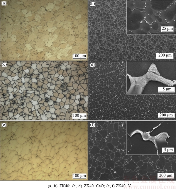
Fig. 1 Optical micrographs (a, c, e) and SEM micrographs (b, d, f) typical of as-cast alloys
The EDXS line scans show the segregation of alloying additions in the ��-Mg matrix of the investigated alloys (Fig. 2). In ZK40, Zn segregates and a higher concentration of Zn was observed near the grain boundary. The segregation is less pronounced in the ZK40-Y alloy while Zn segregation is negligible in ZK40-CaO. The EDXS line scans show inverse segregation of Zr in the ZK40-CaO and ZK40-Y. Ca and Y were detected in the ��-Mg matrix of the ZK40-CaO and ZK40-Y, respectively. However, no appreciable segregation of these elements was observed.

Fig. 2 EDXS line scans for as-cast alloy
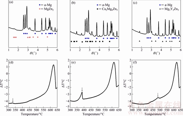
Fig. 3 SRD line profiles (a, b, c) and DTA cooling curves (d, e, f) for ZK40 (a, d), ZK40-CaO (b, e) and ZK40-Y (c, f) alloys
SRD diffraction patterns (Figs. 3(a-c)) show diffraction due to ��-Mg and intermetallic phases, and the intermetallic phases were alloy dependent. The intermetallic phase present in the ZK40 alloy was identified as MgZn2. The ZK40-CaO and ZK40-Y contained Ca2Mg6Zn3 and Mg3Y2Zn3 intermetallic phases, respectively. The DTA curves showed an exothermic peak during cooling from 700 ��C and the formation of ��-Mg occurred in the temperature range of 636-638 ��C (Figs. 3(d-f)). A single peak at 337.7 ��C was observed in ZK40 during cooling. For the ZK40-CaO the peak was at 390.0 ��C and for the ZK40-Y at 499.3 ��C. However, for ZK40-Y, the presence of another exothermic peak may be indicated in the range of 425-450 ��C. On the other hand, only one intermetallic compound was identified in the SRD diffraction pattern (Figs. 3(a-c)). Additionally, the microstructure investigation reveals that only one intermetallic compound was observed. This possible peak can be explained by a minor phase formation or transformation that could not be detected in the SRD diffraction patterns. The same phenomena can also be observed for the ZK40 alloy but significantly less pronounced.
The surface potential differences between micro constituents of the as-cast alloys were investigated using scanning Kelvin probe force microscopy (SKPFM) [45]. Surface potential maps and potential profiles (Fig. 4) show the surface potential difference between the intermetallic phase and the ��-Mg matrix. The intermetallic phases are cathodic with respect to the ��-Mg matrix with the potential difference between the intermetallic compounds and the ��-Mg matrix of (50��20), (50��10) and (65��10) mV for ZK40, ZK40-CaO and ZK40-Y, respectively.
Figure 5 shows the evolution of the hydrogen volume with time for the studied materials in 0.5% (mass fraction) NaCl solution up to 250 h of immersion for ZK40 and ZK40-CaO and 200 h for ZK40-Y (due to a severer corrosion process). For short immersion periods (after 2 days), the total amounts of hydrogen were (1.84��0.05), (0.81��0.06) and (0.14��0.09) mL/cm2 for ZK40-Y, ZK40 and ZK40-CaO alloys, respectively. The amount of hydrogen produced by ZK40-Y was 2.5 times that of the ZK40 and approximately 13 times that of ZK40-CaO. For longer times of immersion, the volume of hydrogen evolved after 200 h exposure is the highest for ZK40-Y followed by ZK40 and the lowest for ZK40-CaO. A peak in hydrogen evolution volume was observed for the ZK40-Y after 75 h.
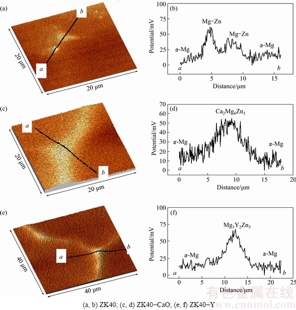
Fig. 4 Surface potential maps (a, c, e) and potential profiles (b, d, f) in selected areas

Fig. 5 Hydrogen evolution in 0.5% NaCl solution for ZK40, ZK40-CaO and ZK40-Y
Figures 6(a-d) shows the EIS results (Nyquist plots and Bode plots) for the investigated alloys after 1 h and 24 h of immersion in 0.5% NaCl solution. Additionally, the equivalent circuit that was used to fit the data is shown with the calculated Nyquist diagrams for the investigated alloys after 24 h immersion (Fig. 6(e)).
The Nyquist plots show a capacitive semi-circle at high and intermediate frequencies, which can be attributed to the charge transfer reaction during the Mg corrosion process. The Randles circuit [46] was chosen as the equivalent circuit (insert in Fig. 6(e)) and it shows the uncompensated solution resistance (Rel), the time constant related to the corrosion process that can be described by the double layer capacitance on the electrolyte/metal interface (CPEdl) and the charge transfer resistance (Rct). A constant phase element (CPE) is used instead of capacitance, so that the non-ideal behaviour of the system can be better modelled [47]. The corresponding calculated electrochemical parameters are given in Table 2. The inductive loop at low frequencies, indicating localised corrosion processes at the Mg surface, was neglected.
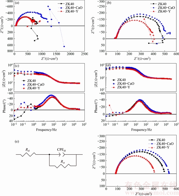
Fig. 6 Nyquist diagrams for investigated alloys obtained by EIS experiment in 0.5% NaCl solution after 1 h (a) and 24 h (b) immersion; Bode plots after 1 h (c) and 24 h (d) immersion; calculated Nyquist diagrams for ZK40 alloy after 24 h immersion as well as equivalent circuit for EIS analysis (e)
Table 2 Simulated parameters used to model EIS data from investigated ZK40, ZK40-CaO and ZK40-Y alloys after 24 h immersion

Rel values were in the range between 80 and 90 ����cm2 and are comparable for all measurements. The estimated resistance values from the diameter of the arcs of the Nyquist plots (Fig. 6(b)) of the ZK40-CaO is ~450 ����cm2, which is higher than that of the ZK40 (~400 ����cm2), and ZK40-Y (~300 ����cm2), indicating higher corrosion resistance of the ZK40-CaO. This tendency can also be observed by the comparison of the calculated charge transfer resistance (Rct) values. ZK40-CaO showed the highest value (1093.0 ����cm2) after 1 h immersion, followed by the ZK40 (702.9 ����cm2). The lowest value was exhibited by ZK40-Y (665.8 ����cm2). All alloys show a continuous decrease of charge transfer resistance with time. After 24 h immersion, the ZK40-CaO alloy exhibited the highest value of Rct (451.3 ����cm2). ZK40 showed a slightly lower value (412.3 ����cm2), whereas the ZK40-Y exhibited the lowest value (329.1 ����cm2) after 24 h immersion. The CPEdl-T value of the dielectric layer of ZK40-CaO (59.2 ��F��cm-2) after 24 h immersion was lower than that of the ZK40 alloy (75.1 ��F��cm-2) and the ZK40-Y alloy (80.8 ��F��cm-2).
Figure 7 shows the results of immersion tests in 0.5% NaCl solution. It provides information on the areas where corrosion attack is more likely to initiate and/or the way it propagates. The surface morphologies of the tested alloys after the removal of the corrosion products after 4 h immersion (Figs. 7(a-c)), 8 h immersion (Figs. 7(d-f)) and 24 h immersion (Figs. 7(g-i)) are shown. Preferential corrosion is observed in the centre of the ��-Mg matrix while the intermetallic phases remain unchanged for the tested alloys. The progress of the dissolution of Mg was alloy dependent. Different types of localised corrosion were responsible for the initial stages of corrosion. For the investigated immersion times, no severe localised corrosion was found for the ZK40 and ZK40-CaO alloys. The three tested alloys showed Mg dissolution from the centre of the grains. ��Microcraters�� with a diameter of ~1 ��m within the grains were present, as highlighted in the inserts of Fig. 7 and most visible in the insert of Fig. 7(f). The regions close to the grain boundary were relatively preserved for the ZK40 and ZK40-CaO alloys, which could also be seen for the ZK40-Y alloy for 4 h (Fig. 7(c)) and for 8 h (Fig. 7(f)) immersions. After 8 h of immersion, the craters were more pronounced in the ZK40-Y (insert in Fig. 7(f)). For the ZK40, the ��microcraters�� appear to coalescence after 24 h immersion (insert in Fig. 7(g)). Larger sites of localised corrosion (��larger craters��) were observed for the ZK40-CaO after 8 h immersion. However, those localised corrosion sites did not evolve into severe localised corrosion after 24 h immersion (Fig. 7(h)). For ZK40-Y, severe corrosion of the ��-Mg matrix was found after 24 h immersion (Fig. 7(i)). In this case, not only the ��-Mg matrix was severely corroded, but also localised corrosion in regions close to the intermetallic compounds was found (insert in Fig. 7(i)). This suggests that the corrosion front rapidly propagates simultaneously in the ��-Mg matrix and grains within the near vicinity.

Fig. 7 SEM-secondary electron (SE) images of planar view with removal of corrosion products after immersion in 0.5% NaCl for 4 h (a-c), 8 h (d-f) and 24 h (g-i)
4 Discussion
The addition of CaO and Y modified the as-cast microstructure of the ZK40 alloy. The modified Mg alloys contained a semi-continuous network of intermetallic phases along the grain boundaries (Fig. 1). During solidification, the first phase to form is the ��-Mg. The ��-Mg nucleation point eventually grows into dendrites due to the fast cooling rate. Zr is a powerful grain refiner for Mg alloys [48]. Thus, the investigated alloys do not exhibit pronounced dendritic microstructure but a near globular morphology. Proceeding the solidification, the inter-dendritic liquid solidifies into intermetallic compounds in the inter- dendritic region. In the case of the ZK40 alloy, the amount of intermetallic compounds that are formed is smaller compared with the modified alloys. These particles are mostly located at triple points because they are normally the last region to solidify. For the modified ZK40-CaO and ZK40-Y alloys, due to the presence of Ca and Y, respectively, the solidification of the inter- dendritic liquid in the last stage is modified. In this case, the amount of intermetallic compounds that are formed is increased and it forms a semi-continuous network in the inter-dendritic region, which corresponds to the grain boundaries of the as-cast material. In the ZE41 alloy, a similar microstructure to that of ZK40-CaO and ZK40-Y alloys was observed [7]. A relatively large segregation of Zn is observed for the ZK40 while a smaller amount of segregation was found in the ZK40-Y (Figs. 2(a, c)). Zr segregation was not pronounced but some inverse segregation was observed in ZK40-CaO and ZK40-Y. The Ca and Y did not segregate within the Mg grains and were distributed along the grain boundaries in the intermetallic phases. Only one intermetallic phase was identified for each investigated alloy, MgZn2, Ca2Mg6Zn3 and Mg3Y2Zn3 for the ZK40, ZK40-CaO and ZK40-Y, respectively. CaO was not observed in the as-cast microstructure, which agrees with WIESE et al [18] who has reported that CaO disassociates during melting and a Ca-rich intermetallic phase was observed in ZK40-CaO. The chemical reaction for the dissociation of CaO is reported by WIESE et al [18] and described as
3Mg+CaO��Mg2Ca+MgO (1)
EIS and hydrogen evolution tests show the highest corrosion resistance for the ZK40-CaO and deterioration of the corrosion resistance for the ZK40 with Y addition. In the EIS, the Nyquist plots show a capacitive loop at high and intermediate frequencies, which is attributed to the charge transfer reaction during Mg dissolution [49]. The equivalent circuit (Fig. 6(e)) shows that the time constant related to the corrosion process can be described by the double layer capacitance on the electrolyte/metal interface (CPEdl) and the charge transfer resistance (Rct). Constant phase elements (CPE) are used instead of capacitance in order to account for non-ideal behaviour of the system [47]. The Rct has decreased for all alloys. The higher Rct in ZK40-CaO alloy indicates lower dissolution of Mg, thus higher corrosion resistance. CPEdl values of the dielectric layer of ZK40-Y are slightly higher than those of ZK40 and ZK40-CaO alloys and attributed to a greater active area in ZK40-Y alloy exposed to the electrolyte due to the increased roughness as the corrosion progressed.
Hydrogen evolution shows different corrosion kinetics over time (Fig. 5). After immersion in an aqueous solution, the film of MgO that forms in contact with air will transform into a porous film of Mg(OH)2. The porous microstructure of the Mg(OH)2 layer in the surface film is attributed to volume expansion from MgO to Mg(OH)2, which causes the disruption of the surface film [50,51]. During the initial stages of corrosion, an incubation period with a low volume of hydrogen evolution is observed, approximately 25 h for the ZK40-Y and 50 h for the ZK40 and ZK40-CaO. Two major factors play a role in the incubation period. The surface layer that exists prior to immersion needs to be dissolved or broken down in order for the ��-Mg matrix to be exposed to the electrolyte and corrode. The breakdown of the corrosion layer is not homogeneous in Mg alloys and repairing the corrosion film is relatively difficult [52]. Even though the dissolved Mg2+ can react with OH- and form Mg(OH)2 on the Mg surface, the loosely deposited Mg(OH)2 film does not necessarily cover the defects on the corrosion layer [52]. Simultaneously, production of hydrogen bubbles in the corroding areas can crack the hydroxide/oxide layer causing localised disruptions to the deposited Mg(OH)2 preventing the corroding areas from being fully covered with the Mg(OH)2. Thus, the ��-Mg matrix is constantly exposed to corrosion and preferential corrosion of the anodic area of the ��-Mg matrix plays the major role, as observed in the immersion tests (Fig. 7). Thus, this corrosion leads to an accelerated period of hydrogen evolution, which reaches a peak at 75 h for the ZK40-Y. This period of accelerated corrosion was not clearly observed for the other alloys. After this period of intensive localised corrosion, the pH tends to increase (intrinsically related to the redox reactions of Mg, which produce OH- as one of the products) [52]. The Mg corrosion products are thermodynamically stable under conditions of high pH [53,54]. Thus, the corrosion front is stabilised, leading to a nearly linear hydrogen volume increase. This is observed after approximately 175 h for all alloys.
The immersion tests (Fig. 7) reveal differences in the initiation of corrosion for the investigated alloys. They show that localised corrosion plays an important role. Chemical segregation and microgalvanic effects are considered to play the major role and they explain the differences in corrosion resistance. Figure 2 shows the EDXS line scans and the difference in intensity along the line is directly related with the difference in chemical composition. For ZK40, the segregation of Zn is notable. At the centre of the grain, the Zn content is lower, and within a region of ~15 ��m along the grain boundary, the Zn content increases in relation to its proximity to the grain boundary. No significant chemical segregation is observed for the ZK40-CaO; whereas for the ZK40-Y, segregation of Zn is similar to ZK40. The regions with higher content of alloying elements act as cathodes compared with the regions with low alloying element content. Such an effect was found for Zn-rich Mg alloys [39] and Zr, RE-rich Mg alloys [38]. In Refs. [55-58], it is also reported that micro-galvanic corrosion can occur between the ��-Mg matrix and the intermetallic phases and between the ��-Mg matrix and the impurities due to higher nobility of the intermetallic particles or impurities compared with the Mg matrix.
The results of the immersion tests after 4 and 8 h show that the grain boundaries were preserved, highlighted in the insert of Figs. 7(a-f). Localised corrosion within the grains was observed. The dissolution of the ��-Mg matrix in the centre of the grain was also observed for 24 h immersion. However, for ZK40-Y, the matrix shows severe corrosion; whereas the general corrosion has not advanced to severe corrosion for ZK40 and ZK40-CaO alloys, which only exhibit localised corrosion at the centre of the grain. The preserved grain boundary regions are attributed to the segregation of Zn resulting in grain boundaries acting as cathodic regions and the middle of the grains as anodic regions.
For the tested alloys, the SKPFM results (Fig. 4) show that the intermetallic compounds were cathodic with respect to the matrix, but the surface potential difference between the ��-Mg matrix and the intermetallic phases was smaller compared with those observed between impurities and the ��-Mg matrix, as reported in Ref. [9]. Thus, it is suggested that the nobility of secondary phases is not sufficiently high to form strong galvanic coupling, which would play an important role in the initiation of corrosion, i.e., localised corrosion at the interface between the intermetallic compounds and the ��-Mg matrix. For Al-Mn inclusions, it is suggested that these particles suffer rapid passivation [59] and therefore show very little influence on the corrosion process and that these inclusions are trapped in intermetallic phase regions with less corrosion susceptibility [60]. The relatively low impurity concentration (Table 1) and significantly higher volume fraction of intermetallic compounds compared with the isolated impurity inclusions suggest that these impurities do not play an important role in the corrosion of the investigated alloys.
After 24 h immersion the more general corrosion exhibiting at earlier time turns into severe localised corrosion for ZK40-Y, suggesting that this alloy was more susceptible to localised corrosion compared with the ZK40 and ZK40-CaO. Galvanic corrosion between the intermetallic compounds and ��-Mg starts to play a role for ZK40-Y after 24 h immersion, as can be seen by the propagation of corrosion along the grain boundaries of the neighbouring grains where severe localised corrosion was observed (insert in Fig. 7(i)). Onset of the severe localised corrosion can explain the accelerated period of hydrogen evolution after 24 h immersion observed in ZK40-Y.
For AZ series Mg alloys [8,9], the intermetallic particles can act as a barrier along the grain boundaries to prevent the advancement of corrosion fronts into the ��-Mg matrix depending on the amount and distribution. However, the presence of intermetallic particles along the grain boundary does not guarantee an effective barrier against corrosion, as observed previously in ZE41 alloy [6]. For the ZK40 modified with 1% Y, the propagation of corrosion along the semi-continuous network of intermetallic compounds indicates it does not provide an effective ��barrier�� hindering corrosion propagation for this alloy. The severe corrosion at early stages, the absence of the ��barrier effect�� and the galvanic corrosion acting on the propagation of corrosion indicate the higher tendency of Mg dissolution in 0.5% NaCl for the ZK40-Y, which can explain its worse corrosion resistance. For the ZK40 modified with addition of CaO, intensive localised corrosion was not observed at the early stages of corrosion. Additionally, the dissolution of the ��-Mg was observed to occur mainly in the region within the grains. No evidence of localised corrosion at the interface between the intermetallic compounds and the ��-Mg matrix was found for this alloy. An important factor that can degenerate the corrosion resistance of an alloy is the chemical segregation in the matrix (micro-segregation). In this case, anodic and cathodic regions will be formed, degenerating the corrosion resistance. The chemical segregation (especially Zn) was found to be significantly smaller for the ZK40-CaO compared with the ZK40 alloy. Furthermore, it is reported by MANDAL et al [28] that Ca can enhance the adherence and insolubility of the Mg(OH)2 layer, which would also enhance the corrosion resistance of Mg alloy containing Ca. In this way, the combination of the mentioned factors can explain the improved corrosion resistance of the ZK40-CaO compared with the ZK40.
5 Conclusions
1) The addition of CaO and Y modified the as-cast microstructure of the ZK40 alloy and CaO was not detected in the as-cast microstructure of the ZK40-CaO alloy. CaO decomposes and is incorporated as Ca forming the intermetallic compounds.
2) The results indicated that the corrosion resistance of ZK40 magnesium alloy is improved with the addition of Ca (ZK40-CaO). The incorporation of Y (ZK40-Y) leads to an inferior corrosion resistance.
3) Due to the low level of impurities, their presence seems to play no important role in the corrosion behaviour of the tested alloys.
4) Chemical segregation and microgalvanic effects are attributed as the main reasons for the differences in corrosion resistance.
5) The lower susceptibility of severe localised corrosion and the formation of more adherent and insoluble corrosion products that are more stable than the Mg(OH)2 due to incorporation of Ca can explain the slightly improved corrosion resistance of the ZK40-CaO. Alternatively, the worse corrosion resistance exhibited by the ZK40-Y can be explained by the severe corrosion at early stages of the corrosion progress, the absence of the ��barrier effect�� and the galvanic corrosion acting on the propagation of corrosion.
Acknowledgements
The authors acknowledge the Deutsches Elektronen-Synchrotron (DESY) for the provision of facilities within the framework of proposal I-20130434. Ricardo Henrique Bozolin acknowledges University of Sao Paulo for granting the fellowship ��Bolsa Empreendedorismo��. Marta MOHEDANO acknowledges the Alexander von Humboldt foundation for the provision of financial support in the form of post-doctoral fellowship.
References
[1] KAINER K U. Magnesium alloys and technology [M]. Weiheim: Wiley-VCH, 2003.
[2] HE S M, PENG L M, ZENG X Q, DING W J, ZHU Y P. Comparison of the microstructure and mechanical properties of a ZK60 alloy with and without 1.3 wt.% gadolinium addition [J]. Materials Science and Engineering A, 2006, 433: 175-181.
[3] WU An-ru, XIA Chang-qing, WANG Jie-wen. Distribution, evolution and the effects of rare earths Ce and Y on the mechanical properties of ZK60 alloys [J]. Journal of University of Science and Technology Beijing, Mineral, Metallurgy, Material, 2006, 13(5): 424-428.
[4] HOMMA T, MENDIS C L, HONO K, KAMADO S. Effect of Zr addition on the mechanical properties of as-extruded Mg-Zn-Ca-Zr alloys [J]. Materials Science and Engineering A, 2010, 527(9): 2356-2362.
[5] CHANG Si-young, TEZUKA Hiroyasu, KAMIO Akihiko. Mechanical properties and structure of ignition-proof Mg-Ca-Zr alloys produced by squeeze casting [J]. Materials Transactions, JIM, 1997, 38(6): 526-535.
[6] ZHAO M C, LIU M, SONG G L, ATRENS A. Influence of microstructure on corrosion of as-cast ZE41 [J]. Advanced Engineering Materials, 2008, 10(1-2): 104-111.
[7] NEIL W C, FORSYTH M, HOWLETT P C, HUTCHINSON C R, HINTON B R W. Corrosion of magnesium alloy ZE41�CThe role of microstructural features [J]. Corrosion Science, 2009, 51(2): 387-394.
[8] COY A E, VIEJO F, SKELDON P, THOMPSON G E. Susceptibility of rare-earth-magnesium alloys to micro-galvanic corrosion [J].Corrosion Science,2010, 52(12): 3896-3906.
[9] APACHITEI I, FRATILA-APACHITEI L E, DUSZCZYK J. Microgalvanic activity of an Mg-Al-Ca-based alloy studied by scanning Kelvin probe force microscopy [J]. Scripta Materialia, 2007, 57(11): 1012-1015.
[10] SUSUKI A, SADDOCK N D, TERBUSH J R, POWELL B R, JONES J W, POLOCK T M. Precipitation strengthening of a Mg-Al-Ca-based AXJ530 die-cast alloy [J]. Metallurgical and Materials Transactions A, 2008, 39(3): 696-702.
[11] HOFSTETTER J, BECKER M, MARTINELLI E, WEINBERG A M, MINGLER B, KILIAN H, POGATSCHER S, UGGOWITZER P J, L FFLER J F. High-strength low-alloy (HSLA) Mg-Zn-Ca alloys with excellent biodegradation performance [J]. The Journal of the Minerals, Metals & Materials Society (TMS), JOM, 2014, 66(4): 566-572.
[12] CHINO Y, UEDA T, OTOMATSU Y, SASSA K, HUANG X, SUZUKI K, MABUCHI M. Effects of Ca on tensile properties and stretch formability at room temperature in Mg-Zn and Mg-Al alloys [J]. Materials Transactions, 2011, 52(7): 1477-1482.
[13] ZHANG B, WANG Y, GENG L, LU C. Effects of calcium on texture and mechanical properties of hot-extruded Mg-Zn-Ca alloys [J]. Materials Science and Engineering A, 2012, 539: 56-60.
[14] GENG L, ZHANG B P, LI A B, DONG C. C. Microstructure and mechanical properties of Mg-4.0Zn-0.5Ca alloy [J]. Materials Letters, 2009, 63(5): 557-559.
[15] SOMEKAWA Hidetoshi, MUKAI Toshiji. High strength and fracture toughness balance on the extruded Mg-Ca-Zn alloy [J]. Materials Science and Engineering A, 2007, 459(1): 366-370.
[16] STANFORD, N. The effect of calcium on the texture, microstructure and mechanical properties of extruded Mg-Mn-Ca alloys [J]. Materials Science and Engineering A, 2010, 528(1): 314-322.
[17] SEONG-HO H A, JIN-KYU L E E, HYUNG-HO J O, SEUNG-BOO J U N G, SHAE K K. Behavior of CaO and Calcium in pure Magnesium [J]. Rare Metals, 2006, 25(6): 150-154.
[18] WIESE B, MENDIS C L, TOLNAI D, STARK A, SCHELL N, REICHEL H P, BR��CKNER R, KAINER K U, HORT N. CaO dissolution during melting and solidification of a Mg-10wt.%CaO alloy detected with in situ synchrotron radiation diffraction [J]. Journal of Alloys and Compounds, 2015, 618: 64-66.
[19]  VLACH M. Structural and mechanical characteristics of Mg-4Zn and Mg-4Zn-0.4Ca alloys after different thermal and mechanical processing routes [J]. Materials Science and Engineering A, 2013, 586: 284-291.
[20] BETTLES C J, GIBSON M A, VENKATESAN K. Enhanced age-hardening behaviour in Mg-4 wt.% Zn micro-alloyed with Ca [J]. Scripta Materialia, 2004, 51(3): 193-197.
[21] GAO X S M Z, ZHU S M, MUDDLE B C, NIE J F. Precipitation- hardened Mg-Ca-Zn alloys with superior creep resistance [J]. Scripta Materialia, 2005, 53(12): 1321-1326.
[22] KATSAROU L, SURESH K, RAO K P, HORT N, BLAWERT C, MENDIS C L, DIERINGA H. Microstructure and properties of magnesium alloy Mg-1Zn-1Ca (ZX11) [C]//Magnesium Technology 2015. Springer International Publishing, 2015: 419-423.
[23] SEONG J W, KIM W J. Development of biodegradable Mg�CCa alloy sheets with enhanced strength and corrosion properties through the refinement and uniform dispersion of the Mg2Ca phase by high-ratio differential speed rolling [J]. Acta Biomaterialia, 2015, 11: 531-542.
[24] GUNDE P,  A C, SOLOGUBENKO A S, UGGOWITZER P J. High-strength magnesium alloys for degradable implant applications [J]. Materials Science and Engineering A, 2011, 528(3): 1047-1054.
[25] YANG Ming-bo, CHENG Liang, PAN Fu-sheng. Comparison about effects of Ce, Sn and Gd additions on as-cast microstructure and mechanical properties of Mg-3.8Zn-2.2Ca (wt%) magnesium alloy [J]. Journal of Materials Science, 2009, 44(17): 4577-4586.
[26] JEONG Y S, KIM W J. Enhancement of mechanical properties and corrosion resistance of Mg-Ca alloys through microstructural refinement by indirect extrusion [J]. Corrosion Science, 2014, 82: 392-403.
[27] RAD B, REZA HBAKHSHESHI RAD Hamid Reza, IDRIS Mohd Hasbullah, KADIR Mohammed Rafiq Abdul, FARAHANY Saeed, FEREIDOUNI Amir, YAHYA Mohd Yazid. Characterization and corrosion behavior of biodegradable Mg-Ca and Mg-Ca-Zn implant alloys [J]. Applied Mechanics and Materials Trans Tech Publications, 2012, 121-126: 568-572.
[28] MANDAL M, MOON A P, DEO G, MENDIS C L, MODAL K. Corrosion behavior of Mg-2.4 Zn alloy micro-alloyed with Ag and Ca [J]. Corrosion Science, 2014, 78: 172-182.
[29] LU Y, BRADSHAW A R, CHIU Y L, JONES I P. Effects of secondary phase and grain size on the corrosion of biodegradable Mg-Zn-Ca alloys [J]. Materials Science and Engineering C, 2015, 48: 480-486.
[30] LUO Z P, ZHANG S Q. High-resolution electron microscopy on the X-Mg12ZnY phase in a high strength Mg-Zn-Zr-Y magnesium alloy [J]. Journal of Materials Science Letters, 2000, 19(9): 813-815.
[31] ITOI T, SEIMIYA T, KAWAMURA Y, HIROHASHI M. Long period stacking structures observed in Mg97Zn1Y2 alloy [J]. Scripta Materialia, 2004, 51(2): 107-111.
[32] MATSUDA M, LI S, KAWAMURA Y, IKUHARA Y, MISHIDA M. Variation of long-period stacking order structures in rapidly solidified Mg97Zn1Y2 alloy [J]. Materials Science and Engineering A, 2005, 393(1): 269-274.
[33] YOSHIMOTO Shintaro, YAMASAKI Michiaki, KAWAMURA Yoshihito. Microstructure and mechanical properties of extruded Mg-Zn-Y alloys with 14H long period ordered structure [J]. Materials Transactions, 2006, 47(4): 959-965.
[34] SINGH A, WATANABE M, KATO A, TSAI A P. Microstructure and strength of quasicrystal containing extruded Mg-Zn-Y alloys for elevated temperature application [J]. Materials Science and Engineering A, 2004, 385(1): 382-396.
[35] XU D K, LIU L, XU Y B, HAN E H. Effect of microstructure and texture on the mechanical properties of the as-extruded Mg-Zn-Y-Zr alloys [J]. Materials Science and Engineering A, 2007, 443(1): 248-256.
[36] KAWAMURA Yoshihito, YAMASAKI Michiaki. Formation and mechanical properties of Mg97Zn1RE2 alloys with long-period stacking ordered structure [J]. Materials Transactions, 2007, 48(11): 2986-2992.
[37] CHINO Yasumasa, SASSA Kensuke, MABUCHI Mamoru. Texture and stretch formability of a rolled Mg-Zn alloy containing dilute content of Y [J]. Materials Science and Engineering A, 2009, 513: 394-400.
[38] BEN-HAMU G, ELIEZER D, SHIN K S, COHEN S. The relation between microstructure and corrosion behavior of Mg-Y-RE-Zr alloys [J]. Journal of Alloys and Compounds, 2007, 431(1): 269-276.
[39] SONG Y, SHAN D, CHEN R, HAN E H. Effect of second phases on the corrosion behaviour of wrought Mg-Zn-Y-Zr alloy [J]. Corrosion Science, 2010, 52(5): 1830-1837.
[40] ELSAYED F R, HORT N, SALGADO ORDORICA M A, KAINER K U. Magnesium permanent mold castings optimization [J]. Materials Science Forum, 2011, 690: 65-68.
[41] AVEDESIAN M M, BAKER H. Magnesium and magnesium alloys, ASM speciality handbook [M]. United States of America: ASM International, 1999.
[42] LUO J, YING K, HE P, BAI J. Properties of Savitzky�CGolay digital differentiators [J]. Digital Signal Processing, 2005, 15(2): 122-136.
[43] SONG Guang-ling, ATRENS Andrej. Understanding magnesium corrosion-a framework for improved alloy performance [J]. Advanced Engineering Materials, 2003, 5(12): 837-858.
[44] SONG Guang-ling, ATRENS Andrej, STJOHN David. An hydrogen evolution method for the estimation of the corrosion rate of magnesium alloys [CJ]//Magnesium Technology 2001. New Orleans: TMS, 2001: 254-262.
[45] JNSSON M. Atmospheric corrosion of magnesium alloys [M]. Influence of Microstructure and Environment. Stockholm, Sweden: Kungliga Tekniska Hgskolan, 2007.
[46] HLADKY K, CALLOW L M, DAWSON J L. Corrosion rates from impedance measurements: An introduction [J]. British Corrosion Journal, 1980, 15(1): 20-25.
[47] BRUNG G J, van den EEDEN A L G, SLUYTERS-REHBACH M, SLUYTERS J H. The analysis of electrode impedances complicated by the presence of a constant phase element [J]. Journal of Electroanalytical Chemistry and Interfacial Electrochemistry, 1984, 176(1-2): 275-295.
[48] STJOHN D H, QIAN M A, EASTON M A, CAO P, HILDEBRAND Z. Grain refinement of magnesium alloys [J]. Metallurgical and Materials Transactions A, 2005, 36(7): 1669-1679.
[49] BARIL Genevi��ve, BLANC Christine,  Nadine. AC impedance spectroscopy in characterizing time-dependent corrosion of AZ91 and AM50 magnesium alloys characterization with respect to their microstructures [J]. Journal of the Electrochemical Society, 2001, 148(12): B489-B496.
[50] SHAW A, in CRAMER S D, COVINO JR B S. Corrosion of magnesium and magnesium-base alloys [M]. Vol. 13A. Materials Park: ASM International, 2003.
[51] YAO H B, LI Y, WEE A T S. An XPS investigation of the oxidation/corrosion of melt-spun Mg [J]. Applied Surface Science, 2000, 158(1): 112-119.
[52] SONG G L. Corrosion of magnesium alloys [M]. Oxford: Woodhead Publishing, 2011.
[53] SONG Guan-ling, ATRENS Andrej. Corrosion mechanisms of magnesium alloys [J]. Advanced Engineering Materials, 1999, 1(1): 11-33.
[54] NORDLIEN J H, ONO S, MASUKO N, NUSANCIONGLU K. A TEM investigation of naturally formed oxide films on pure magnesium [J]. Corrosion Science, 1997, 39(8): 1397-1414.
[55] ZHAO M C, LIU M, SONG G L, ATRENS A. Influence of homogenization annealing of AZ91 on mechanical properties and corrosion behaviour [J]. Advanced Engineering Materials, 2008, 10(1-2): 93-103.
[56] IZUMI Shogo, YAMASAKI Michiaki, KAWAMURA Yoshihito. Relation between corrosion behavior and microstructure of Mg-Zn-Y alloys prepared by rapid solidification at various cooling rates [J]. Corrosion Science, 2009, 51(2): 395-402.
[57] LISITSYN V, BEN-HAMU G, ELIEZER D, SHIN K S. Some particularities of the corrosion behaviour of Mg-Zn-Mn-Si-Ca alloys in alkaline chloride solutions [J]. Corrosion Science, 2010, 52(7): 2280-2290.
[58] BIRBILIS N, EASTON M A, SUDHOLZ A D, ZHU S M, GIBSON M A. On the corrosion of binary magnesium-rare earth alloys [J]. Corrosion Science, 2009, 51(3): 683-689.
[59] MATHIEU S, RAPIN C, STEINMETZ J, STEINMETZ P. A corrosion study of the main constituent phases of AZ91 magnesium alloys [J]. Corrosion Science, 2003, 45(12): 2741-2755.
[60] MINGO B, ARRABAL R, MOHEDANO M, PARDO A, MATYKINA E, RIVAS A. Enhanced corrosion resistance of AZ91 alloy produced by semisolid metal processing [J]. Journal of The Electrochemical Society, 2015, 162(4): C180-C188.
Ricardo Henrique BUZOLIN1,2, Marta MOHEDANO1,3, Chamini Lakshi MENDIS1,4, Beatriz MINGO3, Domonkos TOLNAI1, Carsten BLAWERT1, Karl Ulrich KAINER1, Haroldo PINTO5, Norbert HORT1
1. Magnesium Innovation Centre, Helmholtz-Zentrum Geesthacht, Max-Planck-Strasse 1, D 21502, Geesthacht, Germany;
2. Institute of Materials Science, Joining and Forming, Graz University of Technology, Kopernikusgasse 24/I, 8010 Graz, Austria;
3. Departamento de Ciencia de Materiales, Facultad de Ciencias , Universidad Complutense, Av. Complutense, s/n, 28040 Madrid, Spain;
4. Brunel Centre for Advanced Solidification Technology, Brunel University London, Uxbridge, Middlesex, UB8 3PH, UK;
5. Department of Materials Engineering, University of Sao Paulo, Av. Joao Dagnone, 1100 Jd. Sta Angelina, 13563-120, Sao Carlos, Brazil
ժ Ҫ���о������� ZK40������2% (��������)CaO������1% (��������)Y ��ZK40 þ�Ͻ������֯���������˽����仯���������ò�ͷֲ�������ZK40���紦��ɢ�Ľ����仯�����������������CaO��Y��ZK40������֯����Ϊ�ؾ���ֲ��Ľ����仯����İ���������ṹ������֯��û�м�CaO�� Ca ����������������γɵĽ����仯����Ca2Mg6Zn3�С�����͵绯ѧ�����迹������ʾ������CaO��Ͻ������������ߣ�������Y ȴ��ZK40����ʴ���и���Ӱ�졣������������ʾ�����صľֲ���ʴ���ؽ����仯����ĸ�ʴ��ZK40-Y�Ͻ�ĸ�ʴ��������ҪӰ�죬��ZK40 ��ZK40-CaO �Ͻ�ľֲ���ʴ�����ԡ�ZK40�Ͻ��Ц�-Mg �����е���ƫ�����Ը��ڼ�CaO��Y��ZK40�Ͻ��������ý�ϺϽ�����γ��˸����ȶ�����ʴ����ZK40-CaO�Ͻ����ʴ������ߵ���Ҫԭ��
�ؼ��ʣ�þ�Ͻ�ZK40��Y���ӣ�CaO���ӣ���ʴ��Ϊ
(Edited by Bing YANG)
Corresponding author: Ricardo Henrique BUZOLIN; E-mail: ricardo.buzolin@tugraz.at
DOI: 10.1016/S1003-6326(18)64676-X

