Comparison on construction of strut-and-tie models for reinforced concrete deep beams
来源期刊:中南大学学报(英文版)2011年第5期
论文作者:仇一颗 刘霞
文章页码:1685 - 1692
Key words:reinforced concrete deep beam; topology optimization; strut-and-tie model; genetic evolutionary structural optimization
Abstract: With consideration of the differences between concrete and steel, three solutions using genetic evolutionary structural optimization algorithm were presented to automatically develop optimal strut-and-tie model for deep beams. In the finite element analysis of the first method, the concrete and steel rebar are modeled by a plane element and a bar element, respectively. In the second method, the concrete and steel are assigned to two different plane elements, whereas in the third method only one kind of plane element is used with no consideration of the differences of the two materials. A simply supported beam under two point loads was presented as an example to verify the validity of the three proposed methods. The results indicate that all the three methods can generate optimal strut-and-tie models and the third algorithm has powerful capability in searching more optimal results with less computational effort. The effectiveness of the proposed algorithm III has also been demonstrated by other two examples.
J. Cent. South Univ. Technol. (2011) 18: 1685-1692
DOI: 10.1007/s11771-011-0889-x![]()
QIU Yi-ke(仇一颗), LIU Xia(刘霞)
School of Civil Engineering, Hunan University, Changsha 410082, China
? Central South University Press and Springer-Verlag Berlin Heidelberg 2011
Abstract: With consideration of the differences between concrete and steel, three solutions using genetic evolutionary structural optimization algorithm were presented to automatically develop optimal strut-and-tie model for deep beams. In the finite element analysis of the first method, the concrete and steel rebar are modeled by a plane element and a bar element, respectively. In the second method, the concrete and steel are assigned to two different plane elements, whereas in the third method only one kind of plane element is used with no consideration of the differences of the two materials. A simply supported beam under two point loads was presented as an example to verify the validity of the three proposed methods. The results indicate that all the three methods can generate optimal strut-and-tie models and the third algorithm has powerful capability in searching more optimal results with less computational effort. The effectiveness of the proposed algorithm III has also been demonstrated by other two examples.
Key words: reinforced concrete deep beam; topology optimization; strut-and-tie model; genetic evolutionary structural optimization
1 Introduction
Reinforced concrete deep beams, whose span-depth ratio is less than or equals 5, are frequently used in basement facades, frame-supported shear walls and technical equipment beam-type transition floors. Experimental and theoretical studies have revealed very different mechanical behaviors of deep beams in comparison with shallow beams with large span-depth ratio. Shear failure model of reinforced concrete deep beam is dominated by baroclinic model [1]. Experiments [2-3] in 1980s showed that strut-and-tie models can be introduced for deep beam to simulate its stress mechanism. For instance, the stress mechanism of simply supported deep beams with no hole is usually simulated using the tie-arch model. In practice, holes with different sizes are often opened in deep beams in order to meet the needs posed by pedestrian passage or installation of equipment channels, which makes the stress distribution of deep beams with holes more complex. Currently, a combination of experiment and finite element method is widely used to analyze deep beams with holes. However, no effective algorithm is yet available for building strut-and-tie models of deep beams.
Available tools for generating strut-and-tie models include the program of ANDERHEGGEW and SCHLAICH [4] where a linear programming is used to maximize the plastic capacity of the proposed strut-and- tie model. ALSHEGEIR [5] developed a software utilizing finite-element analysis in which the user should align the strut-and-tie model with the directions of the principal stress. However, ALSHEGEIR did not justify the use of the elastic analysis. In fact, many designs deviate from the elastic strain distribution and yet they are deemed to be good designs [6]. ALI and WHITE [6] presented a consistent and rational approach to generate optimal strut-and-tie models for disturbed D-regions in concrete structures, including criteria for practical reinforcement layout. This approach also moved the D-region design process much closer to the philosophy used in the existing flexural design methods. BRUGGI [7] proposed a simple implementation for minimum compliance optimization relying on the finite element library. GUEST and MOEN [8] employed topology optimization techniques to automate the design of reinforced concrete members. KWAK and NOH [9] introduced the basic idea of the ESO method to determine more rational strut-and-tie models. In their works, in order to prevent the structural instability that may occur during the evolutionary optimization process, a brick element composed of six truss elements was designed as a basic element unit. Several RC structures have been used as examples to demonstrate the capability of the proposed method and to verify the efficiency in application to real design problems. PERERA and VIQUE [10] presented genetic algorithms to automatically produce optimal strut-and-tie models for the design of reinforced concrete beams. In the optimal configuration of their methods, compressive struts are not enforced to be parallel, which allows for representing the physical reality of the flow of forces more consistently. Furthermore, they claimed that the method was more simple and easier than the methods based on the concepts of evolutionary structural optimization. YUN and KIM [11] presented a grid strut-and-tie model approach which allowed for a consistent and effective design of structural concrete, and employed a single type of grid strut-tie model where various load combinations can be considered. The approach performed an automatic selection of the optimal strut-and-tie model by evaluating the capacities of struts and ties using a simple optimization algorithm. Eight reinforced concrete deep beams were tested to failure and the shear wall with two openings were used to verify the validity and effectiveness of the presented approach.
Evolutionary structural method (ESO) [12] is based on the simple idea by slowly removing the inefficient material from a ground structure, and then the residual part evolves towards an optimum. Currently, with the aid of powerful finite element software, evolutionary structural method can be conveniently applied to various structural topological optimization problems, and can provide satisfactory optimal solution. The research on ESO is quite extensive and covers problems with stress, stiffness/displacement, frequency and buckling load constraints [13-16]. The ESO method is considered to be practical and effective optimal method to solve different problems. LIANG et al [17-19] applied this method to construct strut-and-tie models for reinforced concrete structures and pre-stressed concrete structures. To get stronger ability to find the optimal solution, LIU et al [20] improved the classic ESO method and proposed genetic ESO algorithm (GESO). This work focuses on the application of GESO algorithm on building strut-and-tie models of deep reinforced concrete beams. In particular, based on the difference in the elements used in finite element analysis and the treatment in constitutive relation of concrete and cracking characteristics, three different optimization algorithms were proposed to build strut-and-tie models of deep beams. Besides, the performances of the three algorithms were compared to select the algorithm which is most suitable for the problem.
2 Genetic evolutionary structural optimiza- tion (GESO)
GESO combines the genetic algorithm with ESO, in which all elements of a structure generated by finite element analysis constitute the whole population, i.e. each element is an individual of the population. As the evolution progresses, the fittest elements with higher sensitivity values will be conserved while the elements with lower sensitivity values will be deleted. GESO is heuristic, rather than adding and/or removing elements deterministically (according to optimal criteria) in ESO and BESO. An element that satisfies the removing criterion will be deleted or be reserved by chance according to probabilistic mechanism in evolutionary generations. The basic procedure of GESO can be summarized as follows:
1) Build up an original finite element model and determine boundary and load conditions.
2) Impose an n-bits length chromosome whose values of genes are all ‘1’ to each element in the case of the present FEA mesh (n is selected arbitrarily).
3) Solve structural static equation.
4) Calculate sensitivity number αi for each element.
5) Rank individuals according to the sensitivity number αi;
6) Operate mutation over the last m individuals according to ranking, where mutation is slightly different from that of GA and only changes a nonzero gene to zero.
7) Operate crossover in population.
8) Reduce the depths of the elements whose genes have only one ‘0’ to interim depth if the problem is difficult for GESO or skip this step.
9) Remove elements whose values of genes are all ‘0’.
10) Repeat steps 3)-9) until an optimum is reached, or one of the constraints reaches its limit.
3 Three algorithms
3.1 Algorithm I
3.1.1 Analysis model
In the finite element model of reinforcement and concrete, non-coordinated plane elements with four nodes are used, and initially the member is full of reinforcement elements and concrete elements, as shown in Fig.1.
3.1.2 Concrete cracking and treatment of cracking
When the tensile stress of the concrete under loading exceeds the ultimate tolerable stress, the concrete cracks. Cracks reduce the rigidness of the concrete, because the tensile stress can no longer be carried along the surface of cracks, although it can still be carried in the direction parallel to the surface of cracks. In other words, the material gets orthotropic. The modulus of elasticity becomes zero in the direction perpendicular to the surface of crack, and remains the same in the direction parallel to the surface of crack. Therefore, the elasticity matrix Dc of concrete after cracking is [14]
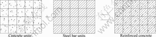
Fig.1 Initial finite element model of reinforced concrete member in Algorithm I
 (1)
(1)
where βG (0≤β≤1) is the shearing modulus along the surface of cracks, reflecting the interlocking of aggregates along the surface, β is dependent on the roughness of the surface and the width of crack, which decreases gradually with the increase of crack width, and equals zero when the crack width is large enough and there is no interlocking among aggregates.
Equation (1) holds in the local coordinate system with x′ axis parallel to the surface of crack (as shown in Fig.2). In the global coordinate system, the elasticity matrix of concrete is
Dc=T![]() T T (2)
T T (2)
where T is the coordinate transformation matrix,
 (3)
(3)
where c=cosθ; s=sinθ.
3.1.3 Failure and treatment after failure of concrete
There are two failure modes for concrete: crushing failure and cracking failure. After cracks appear in concrete elements, the strength of the material is not completely lost, and this situation can be dealt with the method presented in Section 3.1.2. However, with deepening of the evolution process and reduction of reinforcement elements, cracks might appear in new direction. This indicates that the concrete will be divided by two groups of cracks which are along different directions, thus the strength of the material is completely lost and the elastic matrix of the concrete becomes zero.

Fig.2 Stress states of concrete before and after cracking: (a) Before cracking; (b) After cracking
When the principal compressive strain of concrete element is beyond the ultimate tolerable strain, the concrete is crushed and cannot bear stress any more, which implies that the elastic matrix becomes zero. The concrete member is considered to reach the state of failure when a certain number of concrete elements are crushed.
3.1.4 Stress and yielding of reinforcement
Considering that plane unit is used for reinforcement, Mises stress ss of reinforcement is calculated according to Mises yielding conditions in plastic pattern. Ideal elastic-plastic model is used for the constitutive relation of reinforcement:
![]() (4)
(4)
The element does not yield and its modulus of elasticity remains unchanged when ss
3.1.5 Optimization model
The aim of building strut-and-tie models of deep reinforced concrete beams is to find the main force transmission path. In reinforced concrete member, the tensile strength of the concrete varies largely. Therefore, in the evolution process, the concrete elements with tensile stress beyond tolerable the strength will automatically be out of work, and the remaining elements under compression resemble the compressive bars in truss model. Besides, the compression strength of the reinforcement almost remains unchanged in the evolution process, and will not be out of work due to the similar compressive and tensile strength. Therefore, it is optimal to set reinforcement with high working efficiency as tensile bars in truss model. Algorithm I starts with aligning reinforcement elements all over the member, then eliminates the reinforcement elements with low working efficiency and retains more effective elements through calculation, achieving the total elements of reinforcements at last.
The whole process can be formulated as solving an optimization problem:
min ![]()

 (5)
(5)
where Wi is the weight of the reinforcement element i; xi is the indicator of the state of the reinforcement element, and taken to be 1 if reinforcement element exists, and taken to be 0 otherwise; n is the total number of reinforcement elements in the initial model; u is the displacement of the constrained point in the structure; u* is the maximum tolerable displacement of the constrained point in the structure, and can be determined according to specific codes;εc and εcu are the compressive strain and the tolerable compressive strain of concrete, respectively; σs and fy are the tensile stress and tensile strength of the reinforcement, respectively.
3.1.6 Example of simply supported deep flexural member
The example involves a simply supported beam subjected to two concentrated loads, as shown in Fig.3. The two concentrated loads are P1=P2=1 200 kN; the modulus of elasticity of the concrete is taken to be Ec= 28.6 GPa; the modulus of elasticity of the reinforcement is taken to be Es=210 GPa; the Poisson ratio is taken to be ν=0.15; the width of the beam is b=250 mm; the thickness of the reinforcement unit is t=25 mm; εcu= 0.003 3;εtu=0.000 15. In the finite element model, the square length of 100 mm is used to divide the units. The stopping criterion is taken to be the exceed of deflection at the mid-span over the tolerable deflection u*=l/1 500= 12 mm.
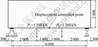
Fig.3 Simple supported beam (Unit: mm)
Figure 4 shows the strut-and-tie model obtained by algorithm I, where the compressive bars in truss model represent concrete elements and the tensile bars represent reinforcement elements. Figure 4 also shows that the force transmission system consists of concrete compressive arc, longitudinal tensile reinforcement bars at the bottom and the inclined reinforcement bars at the bottom.
3.2 Algorithm II
3.2.1 Analysis model
In the reinforced concrete member, different dividing elements are used for reinforcement and concrete, i.e. non-coordinated plane unit with four nodes used for concrete and bar unit used for reinforcement. Initially, the reinforcement units are aligned along the four sides and the diagonal of the concrete unit, as shown in Fig.5.
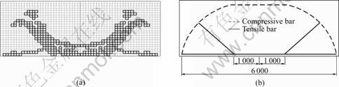
Fig.4 Strut-and-tie model obtained by Algorithm I: (a) Result obtained by GESO: (b) Truss model
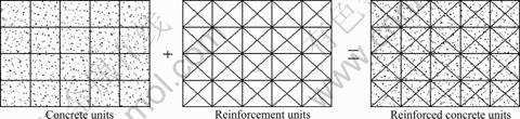
Fig.5 Initial finite element model used in algorithm II
The treatment for cracking and failure of concrete is the same as that presented in Section 2. The evolution process stops if any yielding is found in the reinforcement.
3.2.2 Optimization model
The aim of topology optimization of reinforcement is to find the optimal reinforcement bars layout satisfying the strength and deformation requirements. To achieve this, GESO algorithm starts with aligning reinforcement units all over the member, then eliminates the reinforcement units with low working efficiency and retains more effective units through calculation, achieving the total of reinforcements at last.
The whole process can be formulated as solving an optimization problem:
min ![]()
(6)
3.2.3 Example of simply supported deep flexural member
The same model involving simply supported deep beam in Section 3.1.6 is used here, with the same parameters for the model and the optimization algorithm. Also, the same stopping criterion is used for the optimization algorithm. Figure 6 shows the layout of the reinforcement bars obtained by algorithm II, with the ratio of volume of 5.2%.
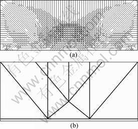
Fig.6 Results obtained by algorithm II: (a) Calculation result; (b) Distribution of steel bars
3.3 Algorithm III
3.3.1 Analysis model
According to GB 50010―2002 [21], the limit state design method is adopted. When structural member reaches its limit state, the concrete in tension will crack and be out of bearing loading. Thus, the loading can be considered to pass through the uncracked tensile reinforcement bars and compressive concrete bars. Therefore, in the application of GESO algorithm to build strut-and-tie model, nonlinear property of the concrete can be neglected and the whole concrete and reinforcement is considered as linearly elastic in finite element analysis. Moreover, performance index is introduced to guide the progress of GESO algorithm. For a displacement optimization problem, the performance index can be calculated by
![]() (7)
(7)
where Ip is the performance index; W0 and Wi are the weights of the original design and the i-th step design, respectively; u0 and ui are the original and the i-th step displacement of controlled point, respectively.
The topology with maximal value of performance index provides the optimal strut-and-tie model. This means that in algorithm III, it is unnecessary to distinguish concrete units with reinforcement units. In algorithm III, the dimension of the cross section of the concrete and the quantity of the reinforcement bars can be designed according to the stress in the compressive and tensile bars in the obtained strut-and-tie model.
3.3.2 Optimization process
The process of algorithm III can be summarized as follows:
1) Considering all the boundary conditions and loading conditions, use plane units to establish the initial finite element model of the structure.
2) Use finite element analysis to evaluate the sensitivity of each unit.
3) Delete the units with low sensitivity after mutation and crossover operator.
4) Compute the structural performance parameter.
5) If the performance parameter is not less than 1, repeat steps 2)-4) until the performance parameter is less than 1. Then, topology with maximal performance parameter value is selected.
6) Build the strut-and-tie model based on the optimal topology, and compute the internal forces in the bars.
7) Based on the calculated internal forces, determine the type of material, the quantity of reinforcement bars and the dimension of the cross section of concrete, which provides the optimal design.
3.3.3 Example of simply supported deep beam
The same model involving simply supported deep beam in Section 3.1.6 is used here, with the same geometric parameters. The results obtained by algorithm III are shown in Fig.7(a), and the corresponding strut- and-tie model is shown in Fig.7(b). The bending moments at the joints are calculated to be very small, implying that the joints in the strut-and-tie model can be assumed to be rigid, which is consistent with the real situation. The model can be treated as compressive and tensile bar model. Also the internal forces in the bars are calculated and shown in Fig.7(b). It is noted that the model in Fig.7(b) is not a truss model, because the joints involved are not hinge joints.
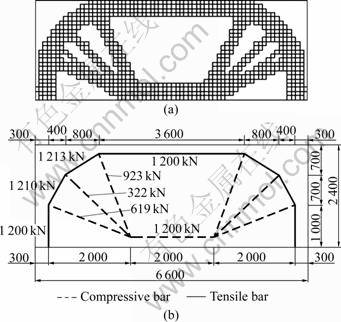
Fig.7 Strut-and-tie model obtained by algorithm III: (a) Result obtained by GESO; (b) Strut-and-tie model (Unit: mm)
Based on the obtained strut-and-tie model and relevant concrete design codes, the dimension of the cross section of the member is designed to be 210 mm × 2 400 mm, HRB400 class of reinforcement bar (fy= 360 N/mm2) and C30 concrete (fc=14.3 N/mm2, ft= 1.43 N/mm2) are used for the member. The cross sectional area of the reinforcement at the mid-span of the member is designed to be 3 333 mm2, and the area values of the three inclined reinforcement bars are 2 564, 894, and 1 719 mm2, respectively, leading to the volume of 0.029 m3 for the reinforcement used in the member. Compared with the total volume of 0.055 m3 for the reinforcement designed according to GB 50010―2002 [21], it can be seen that nearly half of the reinforcement can be reduced using algorithm III.
3.4 Comparison on three algorithms
In this work, three algorithms using GESO are proposed to find the optimal reinforcement alignment, and their performances are illustrated by examples involving a simply supported deep beam. Table 1 shows the comparison results of the three algorithms.
On the whole, algorithm III is the best one among the three algorithms because of its simplicity, practicability and best fitness to GESO algorithm. In algorithm I, although reinforcement is expected to be in tension, and concrete is expected to be in compression, GESO algorithm cannot automatically distinguish between units in tension and those in compression. This means that there will be large quantity of reinforcement in compression if additional condition is not added. On the contrary, the result obtained by GESO will get much worse if additional condition is added to discard the reinforcement element in compression. The topology changes continuously in evolution process, and the element, which is in compression in one evolution step, may be in tension in another evolution step, thus it is not reasonable to discard the element just because it is once in compression during the evolution process.
In algorithm II, bar and plane are respectively used for reinforcement and concrete, and the influence of cracks is also considered, which makes the modeling in this algorithm more consistent with the real simulation, compared with algorithms I and III. However, the result obtained by algorithm II is the worst among the three algorithms, because the result is greatly affected by the meshing and the initial cross-sectional area of the unit. In the initial finite element model adopted by GESO, the meshing and the direction of the reinforcement unit are both specific, and the cross sectional area of the bar (determined from experience) remains the same during the evolution process. As a result, less reinforcement elements are aligned at the places with higher reinforcement demand, more reinforcement elements are aligned at the places with lower reinforcement demand, and the evolution process stops earlier than expected. Although GESO algorithm can adjust the cross sectional area of the bar in evolution process, that is, adjust the quantity of used reinforcement, the resulting effect is still not satisfactory. The reason is that the topology in the process is not the final optimal topology, and the change of cross sectional area in evolution process may change the force transmission path of the member, leading to the derivation of the search path from the optimal solution. In algorithm II, the optimization in topology and cross sectional area is expected to be operated simultaneously, and the result is not up to satisfaction.
Table 1 Comparison of three algorithms
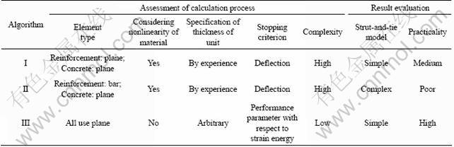
Furthermore, in both algorithm I and algorithm II, it cannot be guaranteed that all reinforcements are in tension in the final topology. Besides, in these two algorithms, the deflection is used as the stopping criterion, and it is required to specify the thickness of the unit or the cross sectional area of the unit from experience, which violates the intension of optimization. According to GB 50010―2002 [21], the quantity of the reinforcement is determined by the ultimate limit state of the structure, thus it is acceptable not to consider the stiffness of the reinforcement and the nonlinearity of concrete when establishing strut-and-tie model. With this insight, in algorithm III, the performance index is used to control the evolution process, leading to the simplicity in calculation process while ensuring the correct alignment of compressive and tensile bars. In conclusion, algorithm III is the best one (among the three algorithms) for building the strut-and-tie model of reinforced concrete member.
4 Two examples
Two examples of the algorithm III are presented in this section. The first one is a simply supported beam in which the ratio of span to height is 2 (see Fig.8(a)). The GESO result is shown in Fig.8(b) and Fig.8(c) is the strut-and-tie model which consists of semi-circle compression and radial tensile bars. The second one is two-pin supported beam in which the ratio of span to height is 2/3 (see Fig.9(a)), the GESO result is shown in Fig.9(b) and Fig.9(c) is its strut-and-tie model which consists of three compressive bars. The difference of the strut-and-tie models between these two deep beams is stemmed from the relative location between the loadings and the bearings. According to the two strut-and-tie model, reinforcements location can be determined. For the beam in Fig.8, the reinforcements should be placed along the radius of the semi-circle; while for the beam in Fig.9, there is no need for any reinforcement to support the loading acting on the top. Then, it can be concluded that it is convenient to acquire practical reinforcement layout for designers with the aid of algorithm III.
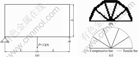
Fig.8 Simply supported beam―Example 1: (a) Ground field; (b) GESO result; (c) Strut-and-tie model
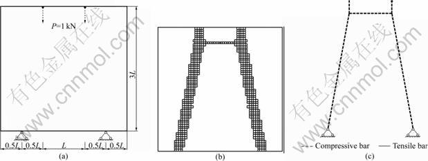
Fig.9 Simply supported beam―Example 2: (a) Ground field; (b) GESO result; (c) Strut-and-tie model
5 Conclusions
1) Algorithm III has powerful capacity in searching more optimal results with less computational effort.
2) The effectiveness of the proposed algorithm III has also been demonstrated from the strut-and-tie models which can be easily used to determine the places of reinforcements of deep beams.
3) Algorithms I and II also have the ability to acquire the optimal reinforcement layout. But, the two algorithms still need improvement to fit the practical purposes.
References
[1] DING Da-jun. Deep beam industrial building [J]. Construction Machines of Science, 1995, 25(3): 41-46.
[2] ROGOWSKY D, MACGREGOR J. The design of reinforced concrete deep beams [J]. Concrete International, 1986, 8(8): 49-58.
[3] COLLINS M, ITCHELL D. A rational approach for shear design―The 1984 canadian code provisions [J]. ACI Structural Journal, 1986, 83(6): 925-933.
[4] ANDERHEGGEN E, SCHLAICH M. Computer-aided design of reinforced concrete structures using the truss model approach [C]// Computer Aided Analysis and Design of Concrete Structures. Swansea UK: Pineridge Press, 1990: 539-550.
[5] ALSHEGEIR A. Analysis and design of disturbed regions with strut-tie models [D]. West Lafayette: Purdue University, 1992: 11- 19.
[6] ALI A A, WHITE R N. Automatic generation of truss model for optimal design of reinforced concrete structures [J]. ACI Structural Journal, 2001, 98(4): 431-442.
[7] BRUGGI M. Generating strut-and-tie patterns for reinforced concrete structures using topology optimization [J]. Computers and Structures 2009, 87(23/24): 1483-1495.
[8] GUEST J K, MOEN C D. Reinforced concrete design with topology optimization [C]// Proceedings of the 19th Analysis & Computation Specialty Conference. Reston: American Society of Civil Engineers, 2010: 445-454.
[9] KWAK H G, NOH S H. Determination of strut-and-tie models using evolutionary structural optimization [J]. Engineering Structures, 2006, 28(10): 1440-1449.
[10] PERERA R, VIQUE J. Strut-and-tie modeling of reinforced concrete beams using genetic algorithms optimization [J]. Construction and Building Materials, 2009, 23(8): 2914-2925.
[11] YUN Y M, KIM B H. Two-dimensional grid strut-tie model approach for structural concrete [J]. Journal of Structural Engineering, 2008, 134(7): 1199-1214.
[12] XIE Y M, STEVEN G P. A simple evolutionary procedure for structural optimization [J]. Computers & Structures, 1993, 49(5): 885-896.
[13] XIE Y M, STEVEN G P. A simple approach to structural frequency optimization [J]. Computers & Structures, 1994, 53(6): 1487-1491.
[14] XIE Y M, STEVEN G P. Evolutionary structural optimization for dynamic problems [J]. Computers & Structures, 1996, 58(6): 1067-1073.
[15] CHU D N. Evolutionary structural optimization method for systems with stiffness and displacement constraints [D]. Melbourne, Australia: Victoria University of Technology, 1997: 25-35.
[16] MANICKARAJAH D, XIE Y M, STEVEN G P. An evolutionary method for optimization of plate bucking resistance [J]. Finite Elements in Analysis and Design, 1998, 29(3/4): 205-230.
[17] LIANG Q Q, XIE Y M, STEVEN G P. Generating optimal strut-and-tie models in pre-stressed concrete beams by performance-based optimization [J]. ACI Structural Journal, 2001, 98(2): 226-232.
[18] LIANG Q Q, XIE Y M, STEVEN G P. Topology optimization of strut-and-tie models in reinforced concrete structures using an evolutionary procedure [J]. ACI Structural Journal, 2000, 97(2): 322-332.
[19] LIANG Q Q. Performance-based optimization of structures [M]. London and New York: Spon Press, 2005: 134-254.
[20] LIU Xia, YI Wei-jian, SHEN Pu-sheng. Genetic evolutionary structural optimization [J]. Journal of Constructional Steel Research, 2008, 64(3): 305-311.
[21] GB 50010―2002. Ministry of Housing and Urban-Rural Development of China. Code for design of concrete structure [S]. (in Chinese)
(Edited by HE Yun-bin)
Foundation item: Project(50908082) supported by the National Natural Science Foundation of China; Project(2009ZK3111) supported by the Science and Technology Department of Hunan Province, China
Received date: 2011-06-13; Accepted date: 2011-08-31
Corresponding author: LIU Xia, Associate Professor, PhD; Tel: +86-13017387719; E-mail: liuxiajy@126.com

