J. Cent. South Univ. Technol. (2011) 18: 2131-2136
DOI: 10.1007/s11771-011-0953-6
A simplified approach for settlement calculation of
pile groups considering pile-to-pile interaction in layered soils
YANG Ming-hui(СоГч»Ф), ZHANG Xiao-wei(ХЕРЎНю), ZHAO Ming-hua(ХФГч»Є)
College of Civil Engineering, Hunan University, Changsha 410082, China
? Central South University Press and Springer-Verlag Berlin Heidelberg 2011
Abstract: A simplified approach is presented for the analysis of the settlement of vertically loaded pile groups. In order to simulate the nonlinear pile-to-pile interaction in pile groups, the soils along the piles are assumed to behave as a series of nonlinear springs subjected to the shaft shear stress at the pile/soil interface. Considering the displacement reduction induced by the pile-to-pile interaction, the shear-deformation method is adopted to approximate the displacement field of the layered soils around the piles, and the equivalent stiffness of the springs is obtained. Furthermore, the load-settlement response of pile groups is deduced by modifying the load-transfer functions to account for the pile-to-pile interaction. The settlements of a laboratory pile groups computed by the presented approach are in a good agreement with measured results. The analysis on contrastive parameters shows that the settlements of pile group decrease with the increase of the pile space and pile length, and the part of piles exceeding the critical pile length has little contribution to the bearing capacity of the pile groups.
Key words: pile groups; settlement; pile-to-pile interaction; load transfer; shear-deformation method
1 Introduction
Piles, generally arranged in groups, are used in various applications to support structures exposed to vertical loads. In many cases, the settlement of pile groups is the controlling factor in design because the primary purpose of pile groups is to limit the deformation of structures. Therefore, many researchers have proposed different methods to investigate the behavior of the settlement of pile groups.
The current methods for estimating the settlement of pile groups can be categorized as: 1) Numerical methods, such as finite element method, and boundary element method. As a very powerful technique, numerical methods can readily calculate the settlements of pile groups in terms of the nonlinearity of soils and the interaction between individual piles by performing full three-dimensional-models for pile groups [1-4]. However, the application of numerical methods is limited in practice for the complex modeling procedures and the high computational requirements, especially for large numbers of pile groups. 2) Equivalent pier methods. The methods consider the pile groups as a whole pier to simplify the procedure for estimating the settlement of pile groups which equals that of single pile by means of load-transfer function [5-7]. The obvious drawback of equivalent pier method is that the computed settlement is only relative to the size of the equivalent pier by neglecting the influence of the pile number and pile space in pile groups. 3) Superimposing methods. The methods, originally introduced by POULOS [8], are widely used recently which estimate the settlements of pile groups by superimposing the interaction factors of any two individual piles. LEE [9] developed a procedure to calculate the interaction factors for both rigid and flexible pile groups. COSTANZO and LANCELLOTA [10] proposed an approximate solution to evaluate the interaction factors taking into account the nonlinearity characteristic of surrounding soil around piles. WONG and POULOS [11] modified the interaction factors which can account for the different type of piles. However, the superimposing method does not consider the reinforcing effects of pile group, i.e. the settlement reduction of soils due to the presence of the neighboring piles. As a result, the computed settlement of pile groups is usually greater than the actual result. Therefore, it is required that developing a simplified approach for estimating the settlement of pile groups considering the reinforcing effect of piles induced by the interaction between individual piles in pile groups which can readily be used in practice.
This work presents a simplified approach to carry out a load-settlement analysis of pile groups subjected to vertical loads in layered soils by using two models. First, the shear-deformation model of soils deduced from the method presented by RANDOLPH and WROTH [12], is developed to simulate the interaction between individual piles in pile groups. The load-transfer model, general used in analyzing the behaviors of single piles, is then extended to estimate the settlement of pile groups by accounting for the interaction between individual piles. Consequently, the relationship between the settlement and the vertical load of pile groups is developed. Results of a certain laboratory on pile groups are used to verify the proposed approach in this work. The influences of the pile space and pile length on the settlement of pile groups are also discussed.
2 Interaction between piles
This work focuses on the vertically-loaded pile groups consisting of n identical piles with the same length L, diameter d, pile space S, and elastic modulus EP embedded in layered soils, as shown in Fig.1(a). Generally, the resistance of the surrounding soils at the pile/soil interface, i.e. shaft frictional force named as tz, is mobilized once the displacement of the piles occurs. The displacement of pile groups at a given depth is different from that of single pile under the same load due to the fact that the reinforcing effect caused by the interaction between some neighboring piles confines the displacement of soils along piles. Therefore, it is necessary to consider the interaction between individual piles in calculating the settlement of pile groups. The soils are assumed to be a series of nonlinear springs attached along the pile shaft to simulate the behaviors of soils subjected to shaft frictional force, as shown in Fig.1(b). Obviously, the stiffness of springs, denoted as the ratio of the shaft frictional force to the displacement of soils, is relative to the interaction between individual piles in pile group.
Considered the interaction between any two piles with the pile space Sij in pile group, i and j, as shown in Fig.2. For pile i, the vertical displacement of the surrounding soil at depth z, defined as wi(z), is composed of three parts: the first, named as wii(z), is caused by the shaft frictional force of pile i itself at depth z; the second is due to the shaft frictional force of pile j at the same depth z, wij(z); the third is the reduction part induced by the reinforce-effect of pile j,  Likewise, the values of the equivalent stiffness of springs are also composed of the same three parts. The procedure of calculating each part of the soil vertical displacement and the equivalent stiffness of springs are presented as follows.
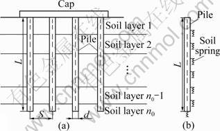
Fig.1 Sketch of pile groups located in layered soils
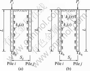
Fig.2 Interaction between two piles in pile group
2.1 Calculation of wii(z)
According to the formulation presented by RANDOLPH and WROTH [12] to estimate the shear- deformation mechanism of surrounding soils around piles subjected to the shaft frictional force tiz, the displacement of a point of soils is expressed as
 (1)
(1)
where r0=d/2, is the radius of the pile; r is the distance from the point of soil to the center of the pile; GS is the shear modulus of soils around the pile shaft, and the expression can be written as below accounting for the layer characteristic of soils:
 (2)
(2)
where GS,i and hi are the shear modulus and the thickness of the i-th layer soil, respectively; rm is the radial distance from the pile centre to a point at which the shaft shear stress induced by the pile can be considered to be negligible. The value of rm can be taken as rm= 2.5rL(1-0.5mS), where the parameter r is the ratio of the shear modulus of soils at the depth L/2 to that of the soil at L, and mS is the Poisson ratio of the soil.
So, the expression of wii(z) is
 (3)
(3)
and the relative equivalent stiffness of the springs is
 (4)
(4)
2.2 Calculation of wij(z)
For pile j, there is also a shaft frictional force at the depth z to resist the vertical load at the pile top, tjz. Likewise, according to the shear-deformation formulation, wij(z) can be written as
 (5)
(5)
Obviously, accounting for all the action of the other piles, the relative equivalent stiffness of springs can be written as
 (6)
(6)
2.3 Calculation of 
This part of displacement of the soil around the pile i is induced by the reinforce-effect of pile j. The value of the stress of pile j at the depth z caused by the spread of tiz, can be expressed as
 (7)
(7)
For pile j, tjiz can be taken as a negative frictional force which pulls pile j down, whereas pile j generates a counter force with the same value but opposite direction namely  which reduces the vertical displacement of the soil around the pile i. Hence, the value of
  is
is
 (8)
(8)
Accounting for all the other piles action, the relative equivalent stiffness of springs can be written as
 (9)
(9)
So, the total equivalent stiffness of springs along pile i can be readily obtained:
 (10)
(10)
3 Procedure for calculating settlement of pile group
3.1 Developing load-transfer function for individual pile in pile groups
The analysis method [13-17], proposed originally by COYLE and REESE [18], is an efficient method to predict the load-settlement relationship for single piles subjected to vertical load for its simplicity and capability of incorporating the nonlinear behavior of soils. However, due to the emission of influence of pile-to-pile interaction on the deformation of the soil surrounding the pile, it is rather difficult to be extended to pile-group analysis. In this work, a load-transfer function is developed based on the analysis of the aforementioned interaction between individual piles in pile group.
Pile i, supported by a series of nonlinear springs along pile shaft or pile bottom to resist the vertical load Pi at the pile top, is taken out to be analyzed separately, as shown in Fig.3(a). The stiffness of spring at the pile bottom can be conveniently expressed using the following equation suggested in Ref.[12]:
 (11)
(11)
where GSb and mSb are the shear modulus and Poisson ratio of the soil at the pile bottom.
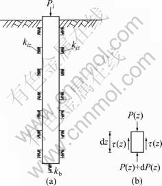
Fig.3 Load-settlement analysis of individual pile in pile-group: (a) Load analysis of pile i; (b) Load analysis of pile j
Considering one element with the finite length dz of pile i at the depth z, all the loads exerting on the finite element can be described as two parts: vertical load located at the top and bottom, P(z) and P(z)+dP(z), and shaft frictional force t(z). The relative differential equation can be established according to the equilibrium condition in vertical direction as
 (12)
(12)
where u is the perimeter of the pile. Besides, the elastic compresstion of the finite element can be expressed as
 (13)
(13)
where AP is the area of the cross-section of pile.
If it is assumed that there is no slipping in the pile/soil interface, substitute Eq.(12) into Eq.(13) so that the load-transfer function of pile i subjected to vertical load can be written as
 (14)
(14)
3.2 Solution for settlement of pile group
If the axial load on the top of pile i is assumed as Pi, the boundary condition of Eq.(14) can be easily expressed as
 (15)
(15)
So, the solution of Eq.(14) may be simplified as
 (16)
(16)
where


Obviously, the value of Eq.(16) when z=0 is the settlement of pile i, which can also be regarded as the settlement of the n-pile group, because the rigid cap makes all the individual pile in pile group deform simultaneously, which can be expressed as
 (17)
(17)
where Q is the total load applied at the center of the cap.
4 Verification by model test
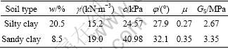
A model test of 3?3 pile group subjected to axial loads in a two-layer soil system is carried out to verify the proposed approach discussed above. A layout of the foundation is shown in Fig.4. Each of the concrete testing pile has an elastic modulus (EP) of 20 GPa with a diameter (d) of 62.5 mm and a length (L) of 2 000 mm. All the piles are placed at an identical space of 4d (d is the pile diameter) and connected at the pile top by a rigid cap made of high-strength organic glass with a elastic modulus Ec=60 GPa. The soil includes the silty clay layer and clay layer with the basic properties listed in Table 1, where w, g, c, j, m represent water content, unit weight, internal cohesion, friction angle, and Poisson ratio, respectively.
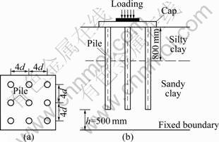
Fig.4 Experimental model of 3ЎБ3 pile-group: (a) Plan view; (b) Cross-sectional view
Table 1 Basic properties of soils in model test
The vertical displacements of the cap also defined as the settlement of pile group are measured by four dial indicators located at each corner of the cap in the loading process, and the average value is considered as the settlement of pile group. A series of tests for pile group are conducted under various vertical loads applied at the center of the cap. Figure 5 shows the comparison between the measured settlements of pile group and the predicted settlements calculated based on the previously presented approach. As it can be seen, the computed results are basically in good agreement with the measurements. Only small differences between them are observed, especially at small loading level, which is similar to the work loading of pile group in actual engineering.
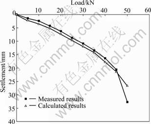
Fig.5 Comparison of computed and measured load-settlement curve for pile group in test
5 Parametric studies
In the design process of pile group, pile space and pile length are two important parameters that determine the cost and the construction difficulty. In order to gain a foundational understanding of the effects of these two parameters on the settlement of pile group, a parametric study for the settlement of pile group is conducted. The basic parameters required are as follows: the piles with pile length L=25 m, diameter d=1.2 m, elastic modulus EP=27 GPa, are placed in an isotropic and homogeneous soil with the shear modulus GS=6 MPa, Poisson ratio mS=0.35, whereas the loading located at the top is kept as a constant P=1 000 kN.
5.1 Influence of pile space
Figure 6 shows the settlements of two kinds of pile groups, 3?3 and 2?2 pile groups, with different pile spaces subjected to the same vertical load. The pile spaces vary from 3d to 9d. It can be seen from the both cases that the settlement of pile group decreases with the increase of pile space if the amount of the piles in pile group is a constant. The reason is that the interaction between individual piles is weakened with the increase of pile space, which indicates that the settlement of pile group induced by other piles has been reduced. Therefore, the pile space of individual pile should be kept as a high value appropriately in the design of pile group.
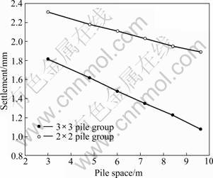
Fig.6 Influence of pile space on settlement of pile-group
5.2 Influence of pile length
The settlements of a 2?2 pile group with different pile lengths are obtained by using the presented approach, as illustrated in Fig.7, where the slenderness of pile is defined as the ratio of the length to diameter of pile. Obviously, the relative settlement decreases with the increase of pile length because more shaft frictional force is mobilized. However, only slight changes can be observed as the pile length reaches a certain value, which indicates that there exists a critical pile length of pile group. In other words, the part of the pile exceeding the critical length only has negligible contributions to the bearing capacity of the pile group. Therefore, the reasonable pile length should be smaller than the critical length which is related to the load, the characteristic of pile and surrounding soil, and the arrangement of pile group.
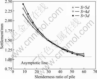
Fig.7 Influence of pile length on settlement of pile group
6 Conclusions
By developing two models to simulate the load-transfer behavior of pile groups in both vertical and lateral directions, a simplified approach for estimating the settlement of pile groups considering the pile-to-pile interaction is presented. Then, pile-group loading test is conducted to verify the proposed approach. Two conclusions can be drawn from the parametric study:
1) The settlement of pile groups decreases with the increase of the pile space when the total amount of the individual piles is kept as a constant.
2) There exists a critical pile length in a fixed arrangement pile group under a certain load. The shaft frictional force pile beyond the critical pile length cannot be mobilized.
References
[1] MOHAMMAD R M, ASADOLLAH N, MANOUCHEH L N. Three-dimensional nonlinear finite element analysis of pile groups in saturated porous media using a new transmitting boundary [J]. International Journal for Numerical and Analytical Methods in Geomechanics, 2008, 32(6): 681-699.
[2] COMODROMOS E M, BAREKA S V. Response evaluation of axially loaded fixed-head pile groups in clayey soils [J]. International Journal for Numerical and Analytical Methods in Geomechanics, 2009, 33(1): 1839-1865.
[3] LI Fei-ran, ZHANG Zhe. Numerical analysis of settlement of bridge pile group foundation [J]. Electronic Journal of Geotechnical Engineering, 2009, 14: 1-9.
[4] YANG X L, ZOU J F. Displacement and deformation analysis for uplift piles [J]. Journal of Central South University of Technology, 2008, 15(6): 906-910.
[5] CLANCY P, RANDOLPH M F. Simple design tools for piled raft foundations [J]. Geotechnique, 1996, 46(2): 313-328.
[6] HORIKOSHI K, RANDOLPH M F. Estimation of overall settlement of piled raft [J]. Soils and Foundation, 1999, 39(2): 59-68.
[7] CASTELLI F, MAUGERI M. Simplified nonlinear analysis for settlement prediction of pile groups [J]. Journal Geotechnical and Geoenvironmental Engineering, ASCE, 2002, 128(1): 76-84.
[8] POULOS H G. Analysis of the settlement of pile groups [J]. Geotechnique, 1968, 18(4): 449-471.
[9] LEE C Y. Pile group settlement analysis by hybrid layer approach [J]. Journal of the Geotechnical Engineering, ASCE, 1993, 119(6): 984-997.
[10] COSTANZO D, LANCELLOTA R. A note on pile interaction factors [J]. Soils and Foundation, 1998, 38(4): 251-253.
[11] WONG S C, POULOS H G. Approximate pile-to-pile interaction factors between two dissimilar piles [J]. Computers and Geotechnics, 2005, 32(8): 613-618.
[12] RANDOLPH M F, WROTH C P. An analysis of the vertical deformation of pile groups [J]. Geotechnique, 1979, 29(4): 423-439.
[13] LEE K M, XIAO Z R. A simplified nonlinear approach for pile group settlement analysis in multilayered soils [J]. Canadian Geotechnical Journal, 2001, 38(5): 1063-1080.
[14] KIM Y G, JEONG S S. Analysis of soil resistance on laterally loaded piles based on 3D soil-pile interaction [J]. Computer and Geotechnics, 2011, 38(2): 248-257.
[15] YANG X L, YIN J H. Slope stability analysis with nonlinear failure criterion [J]. Journal of Engineering Mechanics, 2004, 130(3): 267-273.
[16] HIRAYAMA H. Load-settlement analysis for bored piles using hyperbolic transfer functions [J]. Soils and Foundations, 1990, 30(1): 55-64.
[17] OMER J R, DELPAK R, ROBINSON R B. An empirical method for analysis of load transfer and settlement of single piles [J]. Geotechnical and Geological Engineering, 2010, 28(4): 483-501.
[18] COYLE H M, REESE L C. Load transfer for axially loaded piles in clay [J]. Journal of the Soil Mechanics and Foundations Engineering Division, ASCE, 1966, 92(2): 1-26.
(Edited by DENG LЁ№-xiang)
Foundation item: Project(50708033) supported by the National Natural Science Foundation of China; Projects(200923, CXKJSF0108-2) supported by Transportation Technical Project of Hunan Province, China
Received date: 2011-01-18; Accepted date: 2011-05-30
Corresponding author: YANG Ming-hui, Associated professor; Tel: +86-731-88821659; E-mail: yamih@126.com

