�����Ȼ��������е�������ԭ��Ϊ
��Դ�ڿ����й���ɫ����ѧ��(Ӣ�İ�)2021���5��
�������ߣ����� ���Ӻ� �Ͻ�ΰ ���ұ� ����ʤ ������ �Ⱦ��� ��
����ҳ�룺1496 - 1505
�ؼ��ʣ������ӣ�������ԭ��Ϊ��LiCl-KCl�����Σ�����Һ����ʾ������Դ����
Key words��indium ions; redox behavior; eutectic LiCl-KCl melt; end-of-life LCDs; resources recycling
ժ Ҫ������ѭ����������ʱ��λ�ȵ绯ѧ���������ֶζ�450 ��C��LiCl-KCl��������In(III)�ڶ������ ���ϵĵ绯ѧ��Ϊ����ϵͳ�о������������In(III)�������еĻ�ԭ��һ���������̣��缫��ӦIn(III)/In(I)�� In(I)/In�ֱ�����-0.4 V��-0.8 V (vs Ag/AgCl)����ϻ�ԭ���̵���ת���������ۼ����Լ����λ�������� �ı�����һ��֤��In(III)�������е�������ԭ���ơ����⣬����ѭ�������ͼ�ʱ��λ���Խ�������������� 450 ��C��LiCl-KCl�������е���ɢϵ�����������ַ����õ��������Ǻ����ã����ΪDIn(III)=1.8��10-5 cm2/s��DIn(I)=1.4��10-4 cm2/s��
Abstract: An electrochemical study on the redox behavior of indium in the eutectic LiCl-KCl system at 450 ��C was carried out with the transient techniques of cyclic voltammetry and chronopotentiometry on an inert molybdenum electrode. The reduction of In(III) was found to be a two-step process involving In(III)/In(I) and In(I)/In couples at the potentials of about -0.4 and -0.8 V versus Ag/AgCl, respectively. The redox mechanism was further confirmed by the theoretical evaluation of the number of transferred electrons based on cyclic voltammetry and characterizations of the precipitates generated by the potentiostatic electrolysis. The diffusion coefficients of indium ions in the eutectic LiCl-KCl melt at 450 ��C were estimated by cyclic voltammetry and chronopotentiometry. The results obtained through the two methods are in fair agreement, delivering an average diffusion coefficient of approximately 1.8��10-5 cm2/s for In(III), and 1.4��10-4 cm2/s for In(I).
Trans. Nonferrous Met. Soc. China 31(2021) 1496-1505
Liang XU1,2,3, Yan-hang XIONG2, Jin-wei MENG2, Jia-bao WANG2, Zhong-sheng HUA1,2, Yong-pan TIAN2, Jing-lin YOU3, Zhuo ZHAO1,2
1. Anhui Province Key Laboratory of Metallurgical Engineering & Resources Recycling, Anhui University of Technology, Ma��anshan 243032, China;
2. School of Metallurgical Engineering, Anhui University of Technology, Ma��anshan 243032, China;
3. State Key Laboratory of Advanced Special Steel, Shanghai University, Shanghai 200444, China
Received 15 May 2020; accepted 24 December 2020
Abstract: An electrochemical study on the redox behavior of indium in the eutectic LiCl-KCl system at 450 ��C was carried out with the transient techniques of cyclic voltammetry and chronopotentiometry on an inert molybdenum electrode. The reduction of In(III) was found to be a two-step process involving In(III)/In(I) and In(I)/In couples at the potentials of about -0.4 and -0.8 V versus Ag/AgCl, respectively. The redox mechanism was further confirmed by the theoretical evaluation of the number of transferred electrons based on cyclic voltammetry and characterizations of the precipitates generated by the potentiostatic electrolysis. The diffusion coefficients of indium ions in the eutectic LiCl-KCl melt at 450 ��C were estimated by cyclic voltammetry and chronopotentiometry. The results obtained through the two methods are in fair agreement, delivering an average diffusion coefficient of approximately 1.8��10-5 cm2/s for In(III), and 1.4��10-4 cm2/s for In(I).
Key words: indium ions; redox behavior; eutectic LiCl-KCl melt; end-of-life LCDs; resources recycling
1 Introduction
Indium is a rare and strategic metal due to its extremely low content in the earth crust, which is mainly obtained as a by-product from zinc sulfide ores processing [1-4]. Indium is currently widely used in many high-tech areas because varieties of indium compounds possess excellent semi- conductive or optoelectronic performance [5]. In particular, indium-tin oxide (ITO) film comprised of 90% In2O3 and 10% SnO2 has various favorable properties such as electrical conductivity, optical transparency, thermal reflection, and work functionality, making it an indispensable component of electrode in liquid crystal display (LCD) [6]. Therefore, production of ITO is currently the largest use of indium metal, accounting for approximately 55%-85% of global indium generation [7].
Millions of electronic devices with LCD screens such as computers, mobile phones, laptops, and television sets are being produced and sold every year [8,9]. The huge production of the LCD electronic devices consequently leads to a tremendous increase in indium consumption of over 150 t per year for the LCD fabrication. Based on the upper bound presumption, the demand for indium worldwide will reach as high as 350 t in 2035 [10,11]. The rapidly increasing indium consumption has brought a great challenge to the considerably limited indium reserve base (approximately 16000 t) [9]. On the other hand, the short life cycles of the LCD electronic devices contribute to the increasing generation of end-of- life LCD. For instance, the average life cycle of television sets was reported to be 3-5 years, and that of mobile phones and computers are even shorter [12,13]. In addition to be a sort of solid waste, the end-of-life LCD is one of the most favorable alternative indium resources considering its much higher indium content of up to 1400��10-6 [14], compared to the ordinary sources for indium minerals such as sphalerite and chalcopyrite (10-20)��10-6) [9]. Therefore, efficient recovery of indium from end-of-life LCDs is of great significance for retaining the indium sustainability.
Numerous attempts have been made to recover indium from the end-of-life LCDs via the pyrometallurgical and hydrometallurgical processes [15-17]. However, the traditional pyrometallurgical methods normally involve high temperature and vacuum system costs for quantitative recycling [11], and on the other hand, in hydrometallurgical processes, the acid leaching procedure always generates very dilute solutions with indium concentration of below 50 mg/L [18], which consequently results in difficulties in metallic indium recovery from the leaching solution. An electrochemical approach is considered to be a promising option for the development of sustainable recycling processes. The growth of demand for high purity indium and the low recycling rates of secondary indium resources inspire the research and development of new indium electrolytic recycling technologies. High temperature molten salt plays an important role in modern electrochemical scientific research as well as industrial practices. It has been recently proved that the electrochemical recycling of indium from scrap LCDs in a molten salt medium is technically feasible, representing the great potential of molten salt electrochemistry for application in secondary indium resources recycling [19].
It is one of the most important necessities of understanding the chemistry of indium in order to develop the optimal conditions for the electrochemical recycling process. Several attempts have been made to investigate the electrochemical behavior of indium in molten chloride media such as CaCl2-NaCl [20], ZnCl2-NaCl [21], NaCl- KCl [22], and LiCl-KCl [23-26], but no consensus on the redox mechanism has been found. The disagreement over the explanations on indium redox behavior suggests that further investigations on indium electrochemistry in molten chlorides are indispensable. In this work, a systematic study on indium electrochemical behavior in the eutectic LiCl-KCl system was carried out on an inert molybdenum electrode at 450 ��C. The transient electrochemical techniques such as cyclic voltammetry and chronopotentiometry were employed to investigate the typical redox potentials of indium, reversibility and rate-determining step of the redox reactions, as well as diffusion coefficients of indium ions in the molten melt. The present study aims to provide profound understanding of indium electrochemistry in molten salt media, and more importantly, to serve new electrochemical technology development for the efficient indium recycling from secondary indium resources.
2 Experimental
The schematic diagram of the experimental set-up used in the present work is shown in Fig. 1. The three-electrode electrochemical cell was assembled in a corundum crucible, which was positioned within the constant temperature zone of a cylindrical corundum reactor and heated in an electric furnace. The temperature was determined by a Chromel-Alumel thermocouple with an accuracy of ��1 ��C, and maintained at 450 ��C with a proportional-integral-derivative (PID) thermal controller for each electrochemical measurement. Continuous argon gas circulation of 99.999% purity was applied to guaranteeing an inert atmosphere during the experiment.
All the potentials in this work were with respect to a self-assembled Ag/AgCl (1.0 wt.%) reference electrode in a round bottom mullite tube.

Fig. 1 Schematic diagram of experimental set-up (CE��Counter electrode; RE��Reference electrode; WE�� Working electrode)
A molybdenum wire (1 mm in diameter, 99.95% pure) and a graphite rod (6 mm in diameter, spectroscopically pure) were employed as the working and counter electrodes, respectively. The electrodes were polished with fine abrasive paper and subsequently washed in distilled water and anhydrous ethanol successively with ultrasound to remove impurities on the surface before each measurement.
All the chemical reagents used in the present study were of analytical grade, which were stored in an inert argon atmosphere with the H2O and O2 levels below 1��10-6 in a glove box before using. The eutectic mixture of LiCl-KCl with a mole ratio of 59:41 was initially dehydrated at 300 ��C for over 48 h and pre-melted at 550 ��C for residual moisture removal, which played a role of supporting electrolyte for all the electrochemical measurements. The residual impurities were further removed from the molten salt system by pre-electrolysis at 2.8 V between two graphite electrodes for 2 h. Indium ions to be investigated were introduced into the melt in the form of InCl3 powders with the content of 1.0 wt.%. The three electrodes were inserted into the melt with an immersion area of 0.4788 cm2 for the molybdenum working electrode, and the Ag/AgCl reference electrode was positioned nearby the Mo wire to minimize the disturbance to the current distribution between the working and counter electrodes. The main experiments were allowed to be carried out after 2 h equilibrium between the electrodes and molten salt.
All the electrochemical experiments were carried out with a Parstat 2273 potentiostat from Princeton Applied Research, and the PowerSuite 2.58 software was used to achieve the data acquisition. The transient electrochemical techniques such as cyclic voltammetry and chronopotentiometry were applied to studying the electrochemical behavior of indium in the molten salt. X-ray diffraction (XRD, D8 Advance, Bruker axs) with the monochromatic target of Cu K�� was employed to study the crystal structure of the electrodeposited sample.
3 Results and discussion
3.1 Cyclic voltammetry in blank LiCl-KCl eutectic melt
Electrochemical characterization of the blank LiCl-KCl eutectic melt was carried out to determine the electrochemical window of the molten salt system. Typical cyclic voltammograms were recorded during the cathodic and anodic polarization processes in the eutectic LiCl-KCl melt with a scan rate of 100 mV/s at 450 ��C, as shown in Fig. 2. A graphite electrode was used as the working electrode instead of a Mo wire for the anodic polarization because the electrochemical dissolution of Mo will occur prior to chlorine evolution [20]. It is seen from Fig. 2 that during the cathodic polarization of the Mo electrode, the cathodic current increased rapidly when the potential was negatively swept beyond around -2.60 V, and the reversal of the potential sweep accordingly resulted in an anodic current wave. The redox reactions during the forward and reverse sweeps are attributed to the electrochemical deposition and dissolution of metallic lithium rather than potassium because Li+ is reduced prior to K+ in molten chlorides. On the other hand, the anodic polarization of a graphite electrode exhibited a steep increase in anodic current with the anodic potential sweeping over about 0.80 V, representing the onset of chlorine evolution from the molten salt. The linear portions of the CV curves during both the cathodic and anodic polarization processes are extrapolated to zero-current, and the reversible potentials of Li reduction and Cl2 evolution were accordingly obtained to be -2.70 and 0.94 V, respectively, indicating an electrochemical window of 3.64 V for the eutectic LiCl-KCl melt. The theoretical calculation of the reversibleelectrodes in eutectic LiCl-KCl melt at 450 ��C with scan rate of 100 mV/s (O��Oxidation peak; R��Reduction peak)
decomposition potential of lithium chloride at 450 ��C based on the Nernst equation delivered a result of 3.62 V, which agrees well with the experimental data determined by cyclic voltammetry. Moreover, the residual current within the electrochemical window of the eutectic LiCl-KCl melt is below 10 mA, suggesting that the effects of background disturbances from the supporting electrolyte are negligible for all the electrochemical measurements.
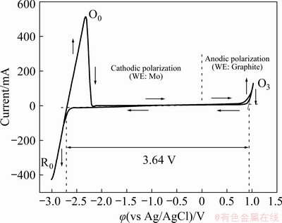
Fig. 2 Cyclic voltammograms of molybdenum (cathodic polarization) and graphite (anodic polarization) working
3.2 Cyclic voltammetry with varied scan ranges
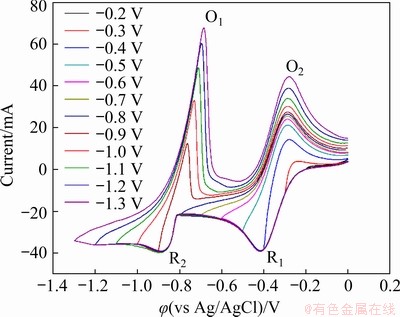
Fig. 3 Cyclic voltammograms in LiCl-KCl-InCl3 (1.0 wt.%) melt at 450 ��C with scan rate of 100 mV/s for varied scan ranges (working electrode: Mo (A= 0.4788 cm2); counter electrode: graphite; reference electrode: Ag/AgCl)
A set of CV measurements were carried out within varied potential ranges at the scan rate of 100 mV/s to study the redox mechanism of indium ions in the molten LiCl-KCl-InCl3 system, and the results are exhibited in Fig. 3. For the potential range of 0 to -0.2 V, no current peak was observed from the CV curve, indicating that no redox reaction involving indium ions occurred within this range. When the scan range was expanded over -0.3 V, the cathodic peak R1 started to appear in the CV curve and its corresponding anodic peak O2 was evident at about -0.3 V during the reversal of potential sweep. The peak shapes of R1 and O2 are characteristics of soluble-soluble redox reactions [21], presumably related to the In(III)/In(I) exchange, derived as the partial reactions expressed in Eqs. (1) and (2):
Peak R1: In(III)+2e��In(I) (1)
Peak O2: In(I)��In(III)+2e (2)
No significant current peak was noticed except the R1/O2 couple by further extending the potential range until -0.8 V, and thereafter a couple of redox peaks R2 and O1 began to appear in the CV curves. This couple of redox peaks became increasingly identified and no more current peak was further observed as the expansion of the scan range to -1.3 V. In contrast to cathodic peak R1, the peak current of R2 increased rapidly with the increase in electrode potential, which is characteristic of the formation of an insoluble substance. Its corresponding anodic peak O1 exhibits the characteristic of a stripping peak, with the current decay steeper than the rise, which further confirms that the reaction system involves an insoluble substance [20]. Therefore, it can be deduced that the redox peaks R2 and O1 are associated with the In(I)/In couple, as described in the partial reactions as Eqs. (3) and (4):
Peak R2: In(I)+e��In (3)
Peak O1: In��In(I)+e (4)
3.3 Cyclic voltammetry with varied scan rates
Cyclic voltammograms within a constant potential range of 0 to -1.3 V at varied scan rates between 100 and 900 mV/s with the step-size of 100 mV/s are shown in Fig. 4. The current peaks O1, O2, R1 and R2 associated with the redox reactions of indium in the molten melt are clearly identified in the CV curve for each scan rate. In general, with the increase of the scan rate from 100 to 900 mV/s, all the redox peaks gradually intensified, and the cathodic peaks R1 and R2 negatively shifted to some extent, whereas the anodic peaks O1 and O2 moved to the positive side slightly.

Fig. 4 Cyclic voltammograms in LiCl-KCl-InCl3 (1.0 wt.%) melt at 450 ��C within scan range of 0 to -1.3 V at varied scan rates (working electrode: Mo (A=0.4788 cm2); counter electrode: graphite; reference electrode: Ag/AgCl)
The reversibility of the redox reactions associated with indium in the molten melt was evaluated based on the relationship between scan rate and peak potential, as recorded in Fig. 5. It is seen that the cathodic peaks shifted 47 mV for R1, and 59 mV for R2 to the negative direction with the increase in scan rate (v) from 100 to 900 mV/s, and the peak potential changes of their corresponding anodic peaks were 32 and 49 mV towards the positive direction for O1 and O2, respectively. The minor potential changes of generally around 50 mV in a wide range of scan rate from 100 to 900 mV/s for all the current peaks involving indium indicate that the kinetics of In(III)/In(I) and In(I)/In is near to the limit for a reversible response [20]. Therefore, it can be concluded that the In(III)/In(I) and In(I)/In redox couples are of quasi-reversibility in the molten LiCl-KCl system.
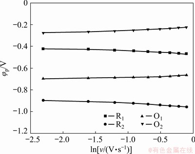
Fig. 5 Dependence of peak potential on natural logarithm of scan rate based on cyclic voltammetry
For an electrochemical reaction system close to reversibility, the following equation is valid to theoretically calculate the number of transferred electrons of the electrode reactions:
��p�C��p/2=2.2RT/(nF) (5)
where ��p represents the peak potential, ��p/2 means the half-peak potential, R is a molar gas constant (8.314 J/(mol��K)), T is the thermodynamic temperature (723.15 K), n is the number of transferred electrons, and F is the Faraday constant (96485 C/mol).
The number of transferred electrons (n) related to the cathodic peaks R1 and R2 were evaluated based on Eq. (5) at varied scan rates between 100 and 900 mV/s. The results for peak R1 delivered an average n value of 1.86, indicating a two-electron exchange process of In(III)/In(I). The mean n value for peak R2 was calculated to be 1.23, which suggests that the reduction of In(I) to metallic In transferring one electron is the main electrode reaction at peak R2. These results show an excellent agreement with the conclusions obtained in Section 3.2 that the redox process of indium follows a two-step mechanism of In(III)/In(I) and In(I)/In in the LiCl-KCl molten salt system.
The peak currents of the redox peaks O1, O2, R1 and R2 were plotted with respect to the square root of the scan rate based on Fig. 4 to further evaluate the rate-determining step of the In(III)/In(I) and In(I)/In systems, as shown in Fig. 6. An excellent linear dependence was clearly evident for each current peak, indicating that all the redox reactions associated with indium in the eutectic LiCl-KCl melt follow the diffusion-controlled mass transfer.
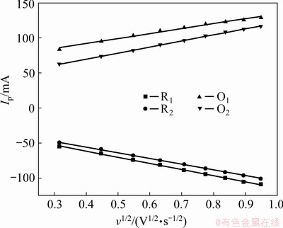
Fig. 6 Dependence of peak current on square root of scan rate based on cyclic voltammetry
As a diffusion-controlled electrochemical system of close to reversibility, the diffusion coefficients of indium ions in the molten LiCl-KCl eutectic can be evaluated with the Randles- Shevchik equation as follows [27]:
Ip=0.4463(nF)3/2(RT)-1/2AD1/2Cv1/2 (6)
where D represents the diffusion coefficient (cm2/s), A is the surface area of the working electrode (0.4788 cm2), and C is the bulk molar concentration of indium ions (mol/cm3).
The diffusion coefficients of indium ions associated with the cathodic peaks R1 and R2 are theoretically calculated with Eq. (6), and the corresponding results are represented in Fig. 7. The deviation given in this figure depends on the varied scan rates of the CV analysis. As the cathodic peak R1 mainly involves the two-electron transfer reduction of In(III) to In(I), n=2 should be valid for In(III) diffusion coefficient evaluation. The result was calculated to be in the range of (1.1-2.5)��10-5 cm2/s with varying the scan rate from 100 to 900 mV/s, which gives a mean DIn(III) value of 1.5��10-5 cm2/s. Similarly, the cathodic peak R2 is associated with the reduction of In(I) to metallic In involving one-electron transfer, and thereby the DIn(I) value was obtained with n=1 based on Eq. (6), delivering an average diffusion coefficient of 9.7��10-5 cm2/s for In(I) ions in the eutectic LiCl-KCl melt at 450 ��C.

Fig. 7 Plots of diffusion coefficients of indium ions versus number of transferred electrons varying from 1 to 3 evaluated based on cyclic voltammetry
3.4 Chronopotentiometry
The electrochemical behavior of indium in the eutectic LiCl-KCl molten salt system at 450 ��C was further studied with chronopotentiometry. The typical chronopotentiograms were obtained by applying varied electrode currents from -10 to -45 mA with the step-size of 5 mA on the Mo working electrode, as shown in Fig. 8.
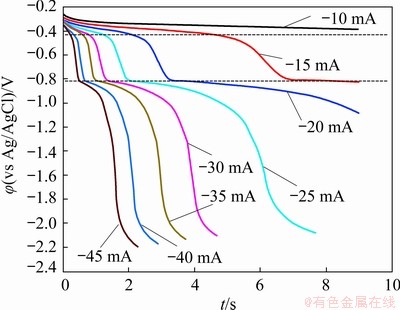
Fig. 8 Typical chronopotentiograms in LiCl-KCl-InCl3 (1.0 wt.%) melt at 450 ��C for varied applied electrode currents (Working electrode: Mo (A=0.4788 cm2); counter electrode: graphite; reference electrode: Ag/AgCl)
Two transition time plateaus are clearly observed from the chronopotentiogram, indicating the two-step reduction process of In(III) in the eutectic LiCl-KCl melt. The plateau identified at about -0.4 V corresponded to the cathodic peak R1 in the cyclic voltammograms, relating to the two-electron transfer reduction of In(III) generating In(I). The plateau at approximately -0.8 V is attributed to the formation of metallic In by the one-electron transfer reduction of In(I), corresponding to the cathodic peak R2 in the aforementioned CV curves. In addition, it can be observed from the chronopotentiogram that the transient time (��) decreased with the increase in the applied electrode current, which further confirms that the electro-reduction process is limited by the diffusion of indium ions in the melt. Therefore, the Sand��s law, which is valid for a diffusion-controlled electrochemical system, can be used to determine the diffusion coefficients of indium ions in the melt, as represented in Eq. (7) [27]:
I��1/2=0.5nFCA(��D)1/2 (7)
The calculated results of diffusion coefficients of indium ions are plotted with respect to the number of transferred electrons in Fig. 9. The deviations of the results are owing to the varied applied electrode currents from -10 to -45 mA. Since the two transition time plateaus R1 and R2 are respectively associated with the In(III)/In(I) and In(I)/In couples, n=2 for plateau R1 and n=1 for plateau R2 are applied in Eq. (7) to evaluate the diffusion coefficients of In(III) and In (I), respectively. The theoretical calculations delivered a mean diffusion coefficient value of 2.0��10-5 cm2/s for In(III), and 1.8��10-4 cm2/s for In(I), which show a fairly agreement with the results obtained based on cyclic voltammetry in Section 3.3.

Fig. 9 Plots of diffusion coefficients of indium ions versus number of transferred electrons varying from 1 to 3 evaluated based on chronopotentiometry
The diffusion coefficients of In(III) and In(I) ions obtained in this study as well as that determined by the previously published research works in molten chlorides are summarized in Table 1. In general, the diffusion coefficients for indium ions at the valance state of +1 in the eutectic LiCl-KCl system can be hardly found fromopen literatures for comparison. BOUTEILLON et al [24,25] evaluated the diffusion coefficient of In(III) in the same molten salt system as that of this study by chronopotentiometry at varied temperatures. An increasing tendency of DIn(III) was clearly evidenced with the increase of temperature from 400 to 550 ��C, because a higher temperature could effectively decrease the viscosity of the molten salt, which accordingly accelerated the diffusion of In(III) ions in the medium. The diffusion coefficient for 450 ��C was given to be 1.3��10-5 cm2/s, which accords closely with the corresponding result of the present study. BARBIER et al [22] investigated the electro- chemical behavior of indium in the NaCl-KCl medium. The results of DIn(III) were determined to be 4.2��10-5 cm2/s by the cyclic voltammetry, and 4.5��10-5 cm2/s by the chronopotentiometry, which are similar to the data for the LiCl-KCl system. CASTRILLEJO et al [20, 21] utilized various methods such as cyclic voltammetry, semi-integral, chronopotentiometry, and chronoamperometry to evaluate the diffusion coefficients of In(III) and In(I) in the molten ZnCl2-NaCl and CaCl2-NaCl media at 450 and 550 ��C, respectively. The results were turned out to be generally lower than that for the LiCl-KCl system, mainly due to the much smaller temperature difference of below 50 ��C between the melting point of the molten melt and operation temperature, resulting in relatively high viscosities of the molten salt media and difficulties in mass transfer for indium ions.
Table 1 Comparison of diffusion coefficients of In(III) and In(I) determined in present study with literature

3.5 Potentiostatic deposition
Potentiostatic electrolysis for indium (species) deposition on the molybdenum working electrode was carried out at the constant potentials of -0.5 and -0.9 V, where the electrochemical signals (R1, R2) were detected in the cyclic voltammograms and chronopotentiograms during the cathodic processes of indium in the eutectic LiCl-KCl melt. After the potentiostatic electrolysis at -0.5 V, the solidified salt mixture was washed with distilled water and no insoluble residue was found, indicating a soluble-soluble reaction system at signal R1 in CV and CP curves, probably due to the In(III)/In(I) couple. Moreover, a small amount of yellow-red powders were observed on the cooling part of the corundum reactor sidewall and the internal surface of the furnace cover, which should be attributed to the condensation of the evaporated InCl from the molten salt medium during the electro-reduction process at -0.5 V and 450 ��C [26], although the sample was not able to be quantitatively collected for further characterizations. This phenomenon further confirms that the signal R1 in the electrochemical measurements is associated with the two-electron transfer reduction of In(III) to In(I) in the eutectic LiCl-KCl melt.
For the potentiostatic deposition at -0.9 V, some spherical metallic precipitates were collected in cathodic region of the molten salt mixture after electrolysis. This is considered to be due to the formation of liquid indium metal (melting point: 156.6 ��C) at the Mo cathode during the electrolytic reduction process which subsequently dropped into the molten melt by gravity. The obtained precipitates were characterized by XRD, and the result is shown in Fig. 10. As can be seen that the XRD pattern exactly matches the standard diffraction peaks of indium metal, representing the deposition of metallic indium by the potentiostatic electrolysis at the electrochemical signals R2 in CVs and CPs, mainly associated with the In(I)/In couple. The characterization results of the products obtained from the potentiostatic electrolytic processes accord well with the aforementioned cyclic voltammetry and chronopotentiometry analysis that the redox behavior of indium follows a two-step mechanism of In(III)/In(I) and In(I)/In in the eutectic LiCl-KCl molten salt system at 450 ��C.
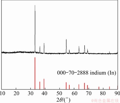
Fig. 10 XRD pattern of precipitate by potentiostatic deposition at -0.9 V
4 Conclusions
(1) The cyclic voltammetry and chrono- potentiometry analysis results indicate that the redox reaction of indium in the eutectic LiCl-KCl melt at 450 ��C is a diffusion-controlled process of quasi-reversibility.
(2) The theoretical evaluation of the number of transferred electrons according to the cyclic voltammetry and characterizations of the precipitates from the potentiostatic electrolysis indicate that the reduction of In(III) follows a two-step mechanism of In(III)/In(I) and In(I)/In.
(3) The diffusion coefficients of indium ions in the eutectic LiCl-KCl melt at 450 ��C were theoretically evaluated based on cyclic voltammetry and chronopotentiometry. The results obtained through the both methods are in fair agreement, as to be DIn(III)=1.5��10-5 cm2/s and DIn(I)=9.7�� 10-5 cm2/s by cyclic voltammetry, and DIn(III)= 2.0��10-5 cm2/s and DIn(I)=1.8��10-4 cm2/s based on chronopotentiometry.
Acknowledgments
The authors are grateful for the financial supports from the National Natural Science Foundation of China (Nos. 51904003, U1703130, 51704011), the China Postdoctoral Science Foundation (No. 2019M651466), and the Foundation of Anhui Province Key Laboratory of Metallurgical Engineering & Resources Recycling of China (Nos. SKF18-01, SKF19-05).
References
[1] ZHANG Fan, WEI Chang, DENG Zhi-gan, LI Cun-xiong, LI Xing-bin, LI Min-ting. Reductive leaching of zinc and indium from industrial zinc ferrite particulates in sulphuric acid media [J]. Transactions of Nonferrous Metals Society of China, 2016, 26: 2495-2501.
[2] CHENG Yong-sheng. Occurrence characteristics and enrichment regularity of indium in pyrite: A case study of Dachang tin ore-field [J]. Transactions of Nonferrous Metals Society of China, 2016, 26: 2197-2208.
[3] LI Xuan-hai, ZHANG Yan-juan, QIN Quan-lun, YANG Jian, WEI Yan-song. Indium recovery from zinc oxide flue dust by oxidative pressure leaching [J]. Transactions of Nonferrous Metals Society of China, 2010, 20: 141-145.
[4] LI Shi-qing, TANG Mo-tang, HE Jing, YANG Sheng-hai, TANG Chao-bo, CHEN Yong-ming. Extraction of indium from indium-zinc concentrates [J]. Transactions of Nonferrous Metals Society of China, 2006, 16: 1448-1454.
[5] LI Yu-hu, LIU Zhi-hong, LI Qi-hou, LIU Zhi-yong, ZENG Li. Recovery of indium from used indium-tin oxide (ITO) targets [J]. Hydrometallurgy, 2011, 105: 207-212.
[6] SILVEIRA A V M, FUCHS M S, PINHEIRO D K, TANABE E H, BERTUOL D A. Recovery of indium from LCD screens of discarded cell phones [J]. Waste Management, 2015, 45: 334-342.
[7] ZENG Xian-lai, WANG Fang, SUN Xiao-fei, LI Jin-hui. Recycling indium from scraped glass of liquid crystal display: Process optimizing and mechanism exploring [J]. ACS Sustainable Chemistry & Engineering, 2015, 3: 1306-1312.
[8] LIM S R, SCHOENUNG J M. Human health and ecological toxicity potentials due to heavy metal content in waste electronic with flat panel displays [J]. Journal of Hazardous Materials, 2010, 177: 251-259.
[9] ZHANG Kai-hua, WU Yu-feng, WANG Wei, LI Bin, ZHANG Yi-nan, ZUO Tie-yong. Recycling indium from waste LCDs: A review [J]. Resources Conservation and Recycling, 2015, 104: 276-290.
[10] WANG Heng-guang, GU Yi-fan, WU Yu-feng, ZHANG Yi-nan, WANG Wei. An evaluation of the potential yield of indium recycled from end-of-life LCDs: A case study in China [J]. Waste Management, 2015, 46: 480-487.
[11] ASSEFI M, MAROUFI S, NEKOUEI R K, SAHAJWALLA V. Selective recovery of indium from scrap LCD panels using macroporous resins [J]. Journal of Cleaner Production, 2018, 180: 814-822.
[12] SCHMIDT M. A production-theory-based framework for analysing recycling systems in the e-waste sector [J]. Environmental Impact Assessment Review, 2005, 25: 505-524.
[13] LAHTI J, VAZQUEZ S, VIROLAINEN S, MNTTRI M, KALLIOINEN M. Membrane filtration enhanced hydrometallurgical recovery process of indium from waste LCD panels [J]. Journal of Sustainable Metallurgy, 2020, 10: 1-13.
[14] TAKAHASHI K, SASAKI A, DODBIBA G, SADAKI J, SATO N, FUJITA T. Recovering indium from the liquid crystal display of discarded cellular phones by means of chloride-induced vaporization at relatively low temperature [J]. Metallurgical and Materials Transactions A, 2009, 40: 891-900.
[15] CHOU Wei-shan, SHEN Yun-hwei, YANG Shien-jen, HSIAO Ting-che, HUANG Lan-feng. Recovery of indium from the etching solution of indium tin oxide by solvent extraction [J]. Environmental Progress & Sustainable Energy, 2016, 35: 758-763.
[16] NAYAK S, DEVI N. Development of hydrometallurgical process for indium recovery from waste liquid crystal display using Cyphos IL 101 [J]. Transactions of Nonferrous Metals Society of China, 2020, 30: 2556-2567.
[17] LI Rui-di, YUAN Tie-chui, FAN Wen-bo, QIU Zi-li, SU Wen-jun, ZHONG Nan-qiang. Recovery of indium by acid leaching waste ITO target based on neural network [J]. Transactions of Nonferrous Metals Society of China, 2014, 24: 257-262.
[18] GRIMES S M, YASRI N G, CHAUDHARY A J. Recovery of critical metals from dilute leach solutions-separation of indium from tin and lead [J]. Inorganica Chimica Acta, 2017, 461: 161-166.
[19] HAARBERG G M, QIN B, MARTINEZ A M. Electrodeposition of indium and tin from molten chloride electrolytes [J]. ECS Transactions, 2017, 77: 1015-1028.
[20] CASTRILLEJO Y, BERMEJO M R, MARTINEZ A M, ABEJON C, SANCHEZ S, PICARD G S. Electrochemical behaviour of indium ions in molten equimolar CaCl2-NaCl mixture at 550��C [J]. Journal of Applied Electrochemistry, 1999, 29: 65-73.
[21] CASTRILLEJO Y, GARCIA M A, BARRADO E, PASQUIER P, PICARD G. Chemical and electrochemical behaviour of indium ions in the ZnCl2-2NaCl melt at 450 ��C [J]. Electrochimica Acta, 1995, 40: 2731-2738.
[22] BARBIER M J, BOUREILLON J, TAOUMI M. An electrochemical study of indium behavior in the fused NaCl-KCl mixture [J]. Journal of The Electrochemical Society, 1986, 133: 2502.
[23] MOHAMEDI M, BOUTEILLON J, POIGNET J C. Electrochemical impedance spectroscopy study of indium couples in LiCl-KCl eutectic at 450 ��C [J]. Electrochimica Acta, 1996, 41: 1495-1504.
[24] BOUTEILLON J, JAFARIAN M, MOHAMEDI M, POIGNET J C. Stability and electrochemical properties of mono and trivalent indium species in fused LiCl-KCl eutectic [J]. Materials Science Forum, 1991, 73: 327-332.
[25] BOUTEILLON J, JAFARIAN M, POIGNET J C, REYDET A. Electrochemical study of the properties of indium in the fused LiCl-KCl eutectic [J]. Journal of The Electrochemical Society, 1992, 139(1): 1-5.
[26] SHAFIR J M, PLAMBECK J A. Gallium and indium electrode potentials in fused LiCl-KCl eutectic [J]. Canadian Journal of Chemistry, 1970, 48: 2131-2132.
[27] BARD A J, FAULKNER L R. Electrochemical methods: Fundamentals and applications [M]. Second ed. John Wiley & Sons Inc, 2001.
�� ��1,2,3�����Ӻ�2���Ͻ�ΰ2�����ұ�2������ʤ1,2��������2���Ⱦ���3���� 1,2
1. ���չ�ҵ��ѧ ұ������Դ�ۺ����ð���ʡ�ص�ʵ���ң�����ɽ 243032��
2. ���չ�ҵ��ѧ ұ��ѧԺ������ɽ 243032��
3. �Ϻ���ѧ ʡ��������Ʒ�������ұ�����Ʊ������ص�ʵ���ң��Ϻ� 200444
ժ Ҫ������ѭ����������ʱ��λ�ȵ绯ѧ���������ֶζ�450 ��C��LiCl-KCl��������In(III)�ڶ������ ���ϵĵ绯ѧ��Ϊ����ϵͳ�о������������In(III)�������еĻ�ԭ��һ���������̣��缫��ӦIn(III)/In(I)�� In(I)/In�ֱ�����-0.4 V��-0.8 V (vs Ag/AgCl)����ϻ�ԭ���̵���ת���������ۼ����Լ����λ�������� �ı�����һ��֤��In(III)�������е�������ԭ���ơ����⣬����ѭ�������ͼ�ʱ��λ���Խ�������������� 450 ��C��LiCl-KCl�������е���ɢϵ�����������ַ����õ��������Ǻ����ã����ΪDIn(III)=1.8��10-5 cm2/s��DIn(I)=1.4��10-4 cm2/s��
�ؼ��ʣ������ӣ�������ԭ��Ϊ��LiCl-KCl�����Σ�����Һ����ʾ������Դ����
(Edited by Xiang-qun LI)
Corresponding author: Zhuo ZHAO, Tel: +86-555-2311571, E-mail: nonferrous_ahut@163.com
DOI: 10.1016/S1003-6326(21)65593-0
1003-6326/ 2021 The Nonferrous Metals Society of China. Published by Elsevier Ltd & Science Press

