Trans. Nonferrous Met. Soc. China 24(2014) 470-476
Establishment of size-dependant constitutive model of micro-sheet metal materials
Xiao-juan LIN1,2, Guang-chun WANG1, Wei ZHENG2, Hua JIANG1, Jin LI2
1. Key Laboratory for Liquid-Solid Structural Evolution and Processing of Material, Ministry of Education, Shandong University, Ji’nan 250061, China;
2. School of Materials Science and Engineering, Shandong Jianzhu University, Ji’nan 250101, China
Received 8 April 2013; accepted 10 October 2013
Abstract: The inherent mechanism of size effect in micro-sheet material behavior of plastic forming was explained by the surface layer model and theory of metal crystal plasticity. A size-dependant constitutive model based on the surface layer model was established by introducing the scale parameters and modifying the classical Hall-Petch equation. The influence of the geometric dimensions and the grain size on the flow behavior of the material was discussed using the new material constitutive model. The results show that, the flow stress decreases while the sheet metal thickness decreases when the grain size keeps constant, and the micro-sheet metal with a larger grain size is more easily to be influenced by the size effects. The material constitutive model established is validated by the stress-strain curve of the micro-sheet metal with different thicknesses derived from the tensile experiments. The rationality of the material model is verified by the fact that the calculation results are consistent with the experimental results.
Key words: sheet metal; micro-forming; constitutive model; scale parameters; pure copper foil
1 Introduction
With the rapid development of electronic industry and precision devices, miniaturization is the trend of the modern manufacture [1]. Micro-forming technology refers to the technology to produce parts with sizes less than 1 mm at least in two dimensional directions using the material plastic forming [2,3]. This technique inherits the characteristics of the traditional plastic processing technology with high productivity, minimum or zero material loss, excellent mechanical properties of the products and small error, and can be used to form tiny parts of a variety of complex shapes. Therefore, the micro-forming technology has very important application prospects in meeting the needs of micro-system technology (MST) and micro parts used in the fields of aerospace, military, medical, microelectronics, textiles and fuel cell, etc [4].
Material flow behavior shows strong size effect during micro-forming process due to the miniaturization of specimen [5,6]. The existing finite element numerical analyzing software based on traditional plastic forming theory is not directly suitable for the micro-forming process simulation because the material model does not include scale parameters.
In the numerical simulation of micro-sheet metal forming process, KU and HWANG [7] simulated the milli-structure rectangular cup drawing using the SPEC plastic forming data and designed the forming process using a systematic approach. KIM and KU [8] proposed a new numerical approach to simulate the micro-strip rolling, by which the polycrystalline material was composed of regular hexagonal crystal grains and the grain unit was connected by the grain boundary unit accounting for shear deformation between grains. This approach was also introduced to laser micro drawing and bulging process. A mixed stress-strain material model was proposed by LAI et al [9] to describe the fine material forming. Combining the theory of material forming in grain and grain boundary based on the surface layer theory, the mechanical properties of the different thicknesses of the stainless steel sheet were obtained through experimental data.
The Taylor factors were given different values to estimate the conditions under which the material properties were likely to be influenced by single grain orientations considering the shear stress of the slip systems for FCC crystal structure by JUSTINGER and HIRT [10] in the aspect of grain orientations. Stated thus, researching on the micro-forming is in its beginning stage and many problems have not yet been explained by the traditional plastic forming theory and molecular dynamics. So, a material constitutive model that can reflect the size effects needs to be established to reveal the micro-sheet metal deformation mechanism and material flow behavior.
In this work, micro-sheet metal is taken as the research object; Hall-Petch equation, a traditional polycrystalline material model, based on the surface layer theory and the crystal plasticity theory of metals, is revised by introducing scale parameters to guarantee accurate numerical simulation of micro-sheet plastic forming process.
2 Scale-dependent material model
2.1 Traditional polycrystalline material constitutive model
The dislocation slip inside a grain needs to overcome the resistance of the grain boundary caused by dislocation pile-up besides the lattice resistance and the resistance of impurity atoms in the slip plane to dislocation as the polycrystalline material formed. The smaller the grain is, the more the grain boundaries are, and the greater the resistance is. Hall-Petch equation is the empirical formula derived from the dislocation pile-up theory, reflecting the effect of the grain size on the material stress-strain relationship [11].
 (1)
(1)
where σi is the frictional resistance that the dislocation slip plane sliding needs to overcome inside a separate individual grain, independent of the grain size; Kd -1/2 is the resisting stress near the grain boundary from the dislocation pile, influenced by the grain size. Taking into account the hardening effect of the plastic forming process, the flow stress of the strain is
 (2)
(2)
where σ(ε) and K(ε) are functions of strain ε without considering the strain rate and temperature effect; d is the average grain size of the material.
2.2 Surface layer theory
GEIGER et al [12,13] found that the flow stress of the material reduced with the reduction of the specimen size when the grain size kept constant in the brass unidirectional compression experiment. This phenomenon can be explained by the surface layer model. Material can be divided into the surface layer grains and the internal grains. In the case of small scale, the ratio of the surface layer grains to the whole grains increases and size of the surface layer becomes thick. In the case of small scale, the surface layer is relatively thick and the number of surface grains has a relative increase when the sample dimensions were scaled down according to the ratio of grain size and deformation scale, just as shown in Fig. 1. Compared with the internal grains, surface grains can deform under a lower flow stress because of less restriction according to the physical principle of metal. This leads to reduction of the flow stress of the total deformed body. This tendency is more obvious when the reduction of the specimen size and its specific surface area increases as the grain size keeps constant.

Fig. 1 Surface layer model
2.3 Analysis of size effects in material flow based on surface layer theory
The difference between the material surface layer grain and internal grain can be ignored since the geometry of the part is much larger than the grain size for macroscopic forming.
However, it is necessary to consider the effects of surface layer grains in the entire deformation since the part is miniaturized. This results in the relative increase in the number of grains of the surface layer during the micro-forming process. For a micro-sheet forming process, when the whole thickness of the sheet only has two or three or even less layers of grains, it can be considered that the whole material is on the surface layer [14,15], as shown in Fig. 2.
A micro-sheet specimen and the longitudinal sectional grain distribution are given in Fig. 3, where L, b and t represent the length, width and thickness of the specimen, respectively. For convenience of description, the grain shape is simplified to quadrilateral in two-dimensional space and the average grain diameter is the side length of the quadrilateral d.

Fig. 2 Surface layer changes with specimen size of micro-sheet metal

Fig. 3 Micro-sheet specimen (a) and longitudinal sectional grain distribution (b)
In Fig. 2, the surface layer grains exist on the free surface, and the sum of the free surface area Ssurf can be understood as the total surface area including the upper and bottom face of the specimen (the side surface area can be neglected because the specimen is very thin).
 (3)
(3)
The actual grain shape is irregular quadrilateral so the grain shape parameters ω1 and ω2 are introduced to describe the influence of the grain shape on the grain volume Vgrain and grain surface area Sgrain.
 (4)
(4)
Let N be grain number, and it is expressed as
 (5)
(5)
The grain is divided into interior region (grain area) and the region near the grain boundary influenced by the dislocation pile (grain boundary area) according to the different forming mechanisms of the resistance as the dislocation moves along the slip plane. Although the grain boundary region is much larger than the actual grain boundary, its size is still tiny relative to the grain size as a whole, so the grain boundary area S can be understood as half the sum of all grain surface area (Any grain shares boundary with adjacent grain because the grains are in contact with each other).
 (6)
(6)
Because of the existence of the free surface in surface layer of grains, the actual grain boundary area is
 (7)
(7)
And Eq. (8) is given according to Eqs. (3), (6) and (7).
 (8)
(8)
The scale parameter η is introduced to describe the influence of the presence of free surface on the total grain boundary area, as the following equation:
 (9)
(9)
where S′ is the actual grain boundary area, and the total grain boundary excepting free surface area; S is the total grain boundary area including outer free surface area.
Equation (10) is given according to Eqs. (3), (6), (7) and (8).
 (10)
(10)
2.4 Modified Hall-Petch equation
σ(ε), the first item in the Eq. (2), is the friction stress that restricts the dislocation sliding along microscopic yield slip band inside the independent individual grain; K(ε)d -1/2, the second item of this formula, is the resistant stress at grain boundaries used to measure the overall yielding generated by the local concentration of stress yielding through the grain boundaries. Thus, the influence of grain boundaries on the flow stress can be analyzed by Eq. (2). Taking into account the large amount of free surface existing in the surface layer grains, the scale parameter η is introduced to Hall-Petch equation which characterizes overall grain boundary area due to the existence of free surface, and the constitutive equation of the micro-sheet metal materials can be described by the following modified Hall-Petch equation:
 (11)
(11)
Equation (12) is given according to Eqs. (10) and (11).
 (12)
(12)
where ω=ω1/ω2 , is the factor related to the grain shape. The crystal grains with different geometric shapes can be described by the different common regular polyhedron models, such as regular tetrahedral, hexahedron and spherical shape. For regular tetrahedral grains, ω=0.068 and for hexahedron shape grains, ω=0.117. The more the faces of a regular polyhedron are, the larger the value of ω is. ω approaches its maximum value of 0.167 when the geometric shape of grains is close to ball [16].
2.5 Scale dependence feature of new materials model
Taking micro-sheet metal as studying case, changes of mechanical properties of materials during plastic forming process caused by scale parameters like geometry size and grain size are studied. The average grain size d of the micro sheet specimen is 25 μm, the grain shape is assumed to be spherical, ω is set to be 0.167, and then the changing trend of scale parameter η with the thickness is shown in Fig. 4.

Fig. 4 Curve of scale parameter vs thickness
Scale parameter η is gradually reaching 1.0 after the sheet thickness t goes beyond 0.4 mm, that is, the thickness of the materials is much larger than the grain size for macro-scale just as shown in Fig. 4. Whereas it decreases with the reduction of the sheet thickness when the sheet thickness t is less than 0.4 mm and this tendency becomes more apparent especially when t is less than 0.2 mm. This shows that with the reduction of the sheet thickness, the ratio of the grains in free surface area to the total surface area increases and the force that hinders dislocation sliding due to the fact that the grain boundary decreases. Under the conditions of the similar organizational structure characteristics, the parameter η characterizing scale impact in the scale-dependent materials model established decreases significantly with the sheet thickness reduction. Thus, the reason why the flow stress decreases with geometric dimensions’ reduction can be directly reflected from the material constitutive model.
The trend that scale parameter η changes with grain size as the micro-sheet thickness t equals 0.1 mm is shown in Fig. 5. It can be seen that with the same thickness, the scale parameter η value decreases if the grain size becomes large. This shows that the larger grain materials tend to be more easily influenced by the size effect.
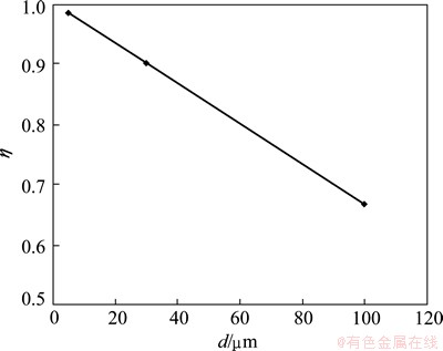
Fig. 5 Relationship between scale parameter and grain size
3 Validations of model
The micro-tensile experimental data in Ref. [17] are used to verify the above material model. The experimental material is stainless steel sheet AISI304 (0Cr18Ni9), the average grain size of material is 25 μm, and the thicknesses are 0.1, 0.2, 0.4 and 1.0 mm, respectively. The true stress-strain curves are given according to the experimental results with different thicknesses, as shown in Fig. 6. The tensile forming of the sample sheet with 1.0 mm thickness can be considered macroeconomic forming due to the fact that its thickness is far greater than the grain size.
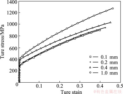
Fig. 6 True stress-strain curves for micro stainless steel sheet with various thicknesses [17]
The tensile experimental data of the specimen with thickness of 1.0 mm in Ref. [17] is regression analyzed using the least squares method, simplifying the flow stress to be function of strain, without considering the influence of strain rate. The undetermined coefficient of Eq. (2) is solved using the true stress-strain curves for polycrystalline materials, and the results are shown in Eq. (13).
 (13)
(13)
Given the grain sample in the literature being spherical, that is, ω equals 0.167, corresponding to three different scale parameter values of 0.916, 0.958 and 0.979, the material stress-strain relationship with three different thicknesses 0.10, 0.20 and 0.40 mm is fitted and compared with the experimental data in the case of grain size of 25 μm, as shown in Fig. 7. The calculated results agree well with the experimental results.
4 Experimental validation
4.1 Uniaxial tensile tests
Uniaxial tensile tests of T2 copper foil specimens were performed to verify the above material model. The copper foil was in rolling state whose chemical composition is shown in Table 1.
The thicknesses of the foil were 0.20 and 0.15 mm, respectively. Heat treatment was performed on the initial material in order to release the influence of work hardening and obtain a certain grain size. With nitrogen servicing as shielding gas, the material was heated to 700 °C, was kept at the temperature for 2 h and cooled in the furnace. The microstructure of pure copper foil after annealing is shown in Fig. 8. The average grain size is 40 μm using the linear intercept method to measure the foil.
Scaling down the non-proportional specimen size according to the national standards, the foil specimens with gauge length of 20 mm and width of 5 mm were prepared using the precision slow-feeding EDM technology, as shown in Fig. 9.
Uniaxial tension experiment was carried out using electronic universal testing machine UTM4203 at the statically loading mode. Figure 10 shows the true stress-strain curves according to the experimental results with different thicknesses.

Fig. 7 Comparison of stress-strain curves between experimental and regressive results
Table 1 Composition of T2 copper foil (mass fraction, %)


Fig. 8 Microstructure of pure copper foil after annealing

Fig. 9 Tensile specimen of pure copper foil
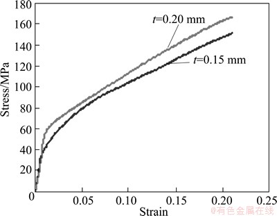
Fig. 10 True stress-strain curves for pure copper foil with different thicknesses
4.2 Validation of model
The tensile experimental data of the copper foil with thickness of 0.20 mm is regression analyzed using the least squares method, simplifying the flow stress to be function of strain, without considering the influence of strain rate. The undetermined coefficient of Eq. (2) is solved using the true stress-strain curves for polycrystalline materials, and the results are shown in Eq. (14).

 (14)
(14)
According to formula (14), the relationship between stress and strain of material with thickness of 0.15 mm can also be fitted and compared with the experimental data, as shown in Fig. 11. From Fig. 7 and Fig. 11, the calculated results agree well with the experimental results. This shows that the material model established has certain rationality, and reflects the characteristics of the scale dependence of micro-sheet metal forming properties.

Fig. 11 Comparison of stress-strain curves between experimental and regressive results at t=0.15 mm
5 Conclusions
The reliable material model is the key to realizing accurate numerical simulation of the micro-sheet plastic forming process. The influence of the free surface on the number of grain boundaries is described by a scale parameter η, considering the theory of dislocation pile-up and surface layer on the basis of the conventional polycrystalline material deformation. Hall-Petch formula suitable for polycrystalline plastic deformation is modified and a size-dependent material model for micro-sheet plastic forming is established. The reason of the material flow stress reducing with the sheet thickness decreasing is revealed by analyzing the tendency of the scale parameter η changing with the sheet thickness; in other words, the material flow stress decreases with the sheet thickness reduction, then the ratio of the grain surface in the free surface area to the total surface area of all grains increases and the hindering force of grain boundary in dislocation sliding becomes less. The influence of grain size on scale parameter in the material model shows that the larger the grain size is, the more obvious the flow deformation size effects of the micro-sheet are. The material model established is validated by true stress-strain curve of micro-sheet with different thicknesses. The calculation results are consistent with the experimental results, indicating certain rationality of the material model. The relationships between stress and strain of material with other geometric size and grain size can be predicted by the material model and the numerical simulation analysis of micro sheet forming in different blank conditions can be realized.
References
[1] ENGEL U, ECKSTEIN R. Microforming-from basic research to its realization [J]. Journal of Materials Processing Technology, 2002, 125-126: 35-44.
[2] KALS T A, ECKSTEIN R. Miniaturization in sheet metal working [J]. Journal of Materials Processing Technology, 2000, 103: 95-101.
[3] ZHANG Kai-feng, LEI Kun. Microforming technology facing to the micromanufacture [J]. China Mechanical Engineering, 2004, 15(12): 1121-1127. (in Chinese)
[4] ZHANG Kai-feng. Micro-manufacturing technology [M]. Beijing: Chemical Industry Press, 2008. (in Chinese)
[5] MAHABUNPHACHAI S, KOC M. Investigation of size effects on material behavior of thin sheet metals using hydraulic bulge testing at micro/meso-scales [J]. International Journal of Machine Tools & Manufacture, 2008, 48: 1014-1029.
[6] SHAN De-bin, YUAN Lin, GUO Bin. Research situation and development trends in micro forming [J]. Journal of Plasticity Engineering, 2008, 15(2): 46-53. (in Chinese)
[7] KU T W, HWANG S M. Milli-component forming of rectangular cup drawing [J]. Journal of Materials Processing Technology, 2001, 113: 749-753.
[8] KIM D J, KU T W. Finite element analysis of micro-rolling using grain and grain boundary elements [J]. Journal of Materials Processing Technology, 2002, 130-131: 456-461.
[9] LAI X M, PENG L F, HU P, LAN S H, NI J. Material behavior modelling in micro/meso-scale forming process with considering size/scale effects [J]. Computational Materials Science, 2008, 43: 1003-1009.
[10] JUSTINGER H, HIRT G. Estimation of grain size and grain orientation influence in microforming processes by Taylor factor considerations [J]. Journal of Materials Processing Technology, 2009, 209: 2111-2121.
[11] ARMSTRONG R W. The yield and flow stress dependence on polycrystal grain size, yield, flow and fracture of polycrystals [M]. London: Applied Science Publishers, 1983.
[12] GEIGER M, MEBNER A, ENGEL U. Production of microparts-size effects in bulk metal forming, similarity theory [J]. Production Engineering, 1997, 4(1): 55-58.
[13] ENGEL U, MEXNER A, GEIGER M. Advanced concept for the FE simulation of metal forming processes for the production of microparts [C]//Proceedings of the Fifth ICTP. Columbus, USA, 1996: 903-907.
[14] ZHENG Wei. Study on modeling and size effects of micro bulk forming [D]. Ji’nan: Shandong University, 2012: 15-60. (in Chinese)
[15] PENG Lin-fa. Modeling, analysis and experimental study of micro/meso scale sheet forming [D]. Shanghai: Shanghai Jiao Tong University, 2007: 21-89. (in Chinese)
[16] WANG Chun-ju, GUO Bin. Polycrystalline model for FE-simulation of micro forming processes [J]. Transactions of Nonferrous Metals Society of China, 2011, 21(6): 1362-1366.
[17] PENG L F, LAI X M. Analysis of micro/mesoscale sheet forming process with uniform size dependent material constitutive model [J]. Materials Science and Engineering A, 2009, 526: 93-99.
微细薄板尺度依赖的材料本构模型的构建
林晓娟1,2,王广春1,郑 伟2,姜 华1,李 锦2
1. 山东大学 材料液固结构演变与加工教育部重点实验室,济南 250061;
2. 山东建筑大学 材料科学与工程学院,济南 250101
摘 要:通过表面层理论和金属晶体塑性变形原理解释微细薄板材料在塑性变形中产生尺寸效应的内在机理。引入尺度参数,对经典的Hall-Petch公式进行修正,建立基于表面层模型理论的尺度依赖材料模型。利用所建立的材料模型分析微细薄板厚度及其晶粒尺寸对材料成形流动性能的影响。在晶粒尺寸一定的情况下,随着微细薄板厚度的减小,材料流动应力逐渐降低;晶粒尺寸越大的微细薄板,其流动变形的尺寸效应现象越明显。利用不同厚度的不锈钢和纯铜箔材的微细薄板拉伸真应力-应变曲线对所建立的材料模型进行验证,计算结果与实验结果比较吻合,验证了所建立的材料模型的合理性。
关键词:薄板;微成形;本构模型,尺度参数,纯铜箔
(Edited by Xiang-qun LI)
Foundation item: Project (50975163) supported by the National Natural Science Foundation of China; Project (IRT0931) supported by Program for Changjiang Scholars and Innovative Research Team in University of Ministry of Education of China
Corresponding author: Guang-chun WANG; Tel: +86-531-88392315; E-mail: wgc@sdu.edu.cn
DOI: 10.1016/S1003-6326(14)63084-3

