高效喷气精炼过程中的机械搅拌
来源期刊:中国有色金属学报(英文版)2011年第8期
论文作者:刘燕 张廷安 佐野正道 王强 任晓冬 赫冀成
文章页码:1896 - 1904
关键词:喷气精炼;偏心搅拌;单向转动;气泡分散;气泡细化;宏观流
Key words:gas injection refining; eccentric mechanical stirring; unidirectional impeller rotation; bubble dispersion; bubble disintegration; macroscopic flow
摘 要:在喷气精炼过程中,气泡的分散和细化是提高精炼效率的必要条件。在水模型实验中应用了单向的偏心搅拌模式来寻找最佳的气泡微细化条件。影响气泡微细化的因素有:搅拌模式、偏心度、搅拌转速、喷嘴结构、喷嘴的浸入深度以及气体流量。气体的喷入方式包括两种,一是从搅拌桨下方的喷嘴中直接喷入,二是从一个位于搅拌桨下方的弯管中喷入。在偏心搅拌模式下,漩涡远离了搅拌桨的轴心,小气泡产生于搅拌桨附近的强湍流或高剪切应力场中,随着机械搅拌产生的宏观流向漩涡方向移动。因此,单向的偏心搅拌模式能促进气泡在溶池内的细化和分散。
Abstract:
In gas injection refining processes, wide dispersion of small bubbles in the bath is indispensable for high refining efficiency. Eccentric mechanical stirring with unidirectional impeller rotation was tested using a water model for pursuing better bubble disintegration and dispersion. Effects of various factors on bubble disintegration and dispersion were investigated. These factors were stirring mode, eccentricity and rotation speed, nozzle structure, nozzle immersion depth, and gas flow rate. Gas injection from a nozzle at the end of the impeller shaft and from an immersed lance was studied. Under eccentric stirring, a vortex was formed away from the shaft. Small bubbles were produced in the strong turbulence or high shear stress field near the rotating impeller and moved in the direction to the vortex keeping up with the macroscopic flow induced by the mechanical stirring. Thus small bubbles could disperse widely in the bath under eccentric stirring with unidirectional rotation.

LIU Yan1, ZHANG Ting-an1, Masamichi SANO2, WANG Qiang1, REN Xiao-dong1, HE Ji-cheng1
1. Key Laboratory of Ecological Utilization of Multi-metal Intergrown Ores of Ministry of Education,
School of Materials and Metallurgy, Northeastern University, Shenyang 110004, China;
2. Department of Materials Processing Engineering, Nagoya University, 464-8603, Japan
Received 25 November 2010; accepted 16 May 2011
Abstract: In gas injection refining processes, wide dispersion of small bubbles in the bath is indispensable for high refining efficiency. Eccentric mechanical stirring with unidirectional impeller rotation was tested using a water model for pursuing better bubble disintegration and dispersion. Effects of various factors on bubble disintegration and dispersion were investigated. These factors were stirring mode, eccentricity and rotation speed, nozzle structure, nozzle immersion depth, and gas flow rate. Gas injection from a nozzle at the end of the impeller shaft and from an immersed lance was studied. Under eccentric stirring, a vortex was formed away from the shaft. Small bubbles were produced in the strong turbulence or high shear stress field near the rotating impeller and moved in the direction to the vortex keeping up with the macroscopic flow induced by the mechanical stirring. Thus small bubbles could disperse widely in the bath under eccentric stirring with unidirectional rotation.
Key words: gas injection refining; eccentric mechanical stirring; unidirectional impeller rotation; bubble dispersion; bubble disintegration; macroscopic flow
1 Introduction
Highly efficient gas injection refining cannot be realized without wide dispersion of small bubbles in a bath. In conventional processes, however, a large amount of gas is injected from a small number of nozzles into the bath in a short time, thus very large bubbles are inevitably formed and dispersed locally in the bath. What is worse, such large bubbles rise up very rapidly with the upward mixed flow of gas and liquid. As a result, their residence time in the bath becomes short to make the gas-liquid contact very poor [1-3].
Production and wide dispersion of small bubbles in liquid are not difficult at low temperatures. For example, many sophisticated devices are used successfully for the purposes in chemical industry [4-5]. Since iron and steel refining processes are operated at very high temperatures, such sophisticated devices cannot be used in actual plants.
In degassing and inclusion removal of molten aluminum, small bubbles can be produced using a gas injection nozzle or rotor rotating at high speed (6-10 r/s). Under centric mechanical stirring, where the nozzle or rotor shaft is placed at the vessel center, a vortex of reverse cone shape is formed around the shaft at the high rotation speed. In this case, the injected bubbles gather near the vortex and cannot disperse widely in the bath. Therefore, installation of baffles is required for preventing the vortex formation [6]. It has been proposed that this vortex formation can also be prevented by forward-reverse rotation of the rotor [7-8]. The wide dispersion of small bubbles in the bath makes the melt surface calm and reduces splash formation. These phenomena help reduction of slag entrainment into the melt and effective prevention of oxidation of aluminum under oxidizing atmosphere.
Centric mechanical stirring with unidirectional impeller rotation is used for hot metal desulfurization. This is called KR method in iron and steel making. The aim of the mechanical stirring is to entrain the desulfurization flux powder into the melt. In the method, a four-blade impeller, the rotation speed of which is lower than 2.5 r/s, is used to make a vortex around the impeller shaft. This vortex formation is needed for the powder entrainment. NOMURA and IGUCHI [9] showed that eccentric mechanical stirring can also achieve effective powder entrainment into liquid. They placed an impeller shaft distant from the vessel center to form a vortex distant from the shaft.
In the previous papers [4-5], the present authors reported water model experiments for the purpose of applying the mechanical stirring to gas injection refining operated at high temperatures. Since the refractory impeller rotating at high speed is easily eroded in iron and steel making processes, the rotation speed of the impeller was set lower than 2.5 r/s. Gas was injected from a four-hole nozzle installed at the end of the impeller shaft. They showed that the bubble disintegration and wide dispersion in the bath can be realized without installation of baffles by forward-reverse impeller rotation. But this rotation mode makes the necessary stirring power high. In addition, the load acting on the impeller blades is very large because of the inversion of impeller rotation. Therefore, the strength required for the blades is very high.
In the present water model experiment [10-17], we adopted mechanical stirring with unidirectional four-blade impeller rotation for bubble disintegration and dispersion in a bath. Baffles were not installed at the vessel wall. Since the vortex formation around the impeller shaft has a fatal effect on the gas-liquid contact, the impeller shaft was placed distant from the vessel center. This is called eccentric mechanical stirring. Air was injected into water from a nozzle installed at the end of the impeller shaft or from an immersion lance. Effects of various operating factors on the phenomena were examined. It is demonstrated that small bubbles produced in the strong shear field near the impeller travel keeping up with the macroscopic flow to the vortex distant from the impeller and disperse widely in the bath.
2 Experimental
The experimental apparatus is shown in Fig. 1. The container of water was made of acrylic resin. The diameter was 0.433 m, and the height was 0.51 m. The photo in Fig. 2 shows the side view of the thick four-blade impeller and four-hole nozzle. The blade length, height and thickness of the impeller were 0.22, 0.05, and 0.04 m, respectively. The diameter of the impeller shaft was 30 mm. The four-hole nozzle was attached to the center of the impeller underside. Four holes of 2 mm diameter were drilled at the side of a hollow cylinder of 30 mm outer diameter and 38 mm length. The holes were located 10 mm from the cylinder bottom. In additional experiments, gas was injected horizontally or vertically upward from a hole at the side or end of an immersion lance.
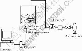
Fig. 1 Experimental apparatus
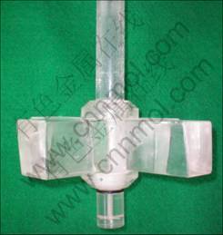
Fig. 2 Photo of four-blade impeller and four-hole nozzle
The impeller rotation was unidirectional, the rotation speed was 0.83-2.5 r/s and the distance between the impeller shaft and the vessel center was 0.02-0.08 m. The eccentricity of the impeller shaft, which was defined as the ratio of the distance to the vessel radius, was 0.092-0.370. The behavior of gas injected into water was recorded by a high-speed video camera (500 frame/h). The moving picture image was input into a computer. The distribution of bubble size was measured using an image-processing software.
3 Results and discussion
3.1 Macroscopic flows induced by mechanical stirring
The macroscopic flows induced by mechanical stirring have decisive effects on the bubble disintegration and dispersion in liquid. The pictures of vortex formation under centric and eccentric stirring without gas injection are shown in Figs. 3(a) and (b). The impeller rotation speed was 2.5 r/s, and the impeller immersion depth ( the distance from the bath surface to the upper face of the impeller blade) was 0.16 m.In Fig. 3(b), the eccentricity of the impeller was 0.370. The calculated result of the macroscopic flow under centric and eccentric stirring are shown in Figs. 4(a) and (b). Figure 4(b) shows the calculated result by a turbulent flow model [18]. As compared with the centric stirring, the eccentric stirring creates a very complex macroscopic flow.
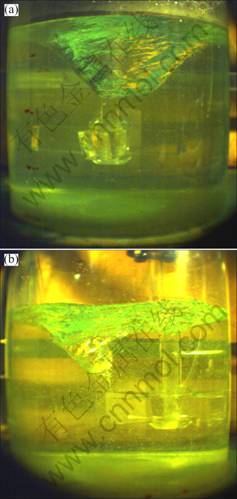
Fig. 3 Vortex formation under centric (a) and eccentric (b) stirring with unidirectional rotation
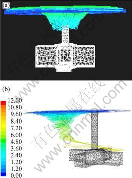
Fig. 4 Numerical calculation on movement of fluid particle under centric (a) and eccentric (b) stirring with unidirectional rotation
The horizontal tangential flow is closely related with the vortex formation, which strongly affects the bubble dispersion in liquid. Since the tangential flow under centric stirring is axially symmetric and very strong, a large vortex is formed around the impeller shaft. On the other hand, the tangential flow under eccentric stirring is axially asymmetric. As can be seen from Fig. 3, the vortex formed under eccentric stirring is smaller than that formed under centric stirring. Hence, the tangential flow induced by eccentric stirring is relatively weak.
The position of the vortex formed under eccentric mechanical stirring is dependent on various factors, such as impeller shape, size, rotation speed, eccentricity, and immersion depth. As an example, the effect of the impeller immersion depth on the position of the vortex is shown in Fig. 5. The eccentricity of the impeller was 0.370. The impeller rotation speed was 1.67 s-1. The distance from the vortex center to the impeller shaft increased with the immersion depth of the impeller.
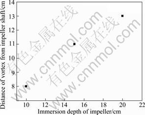
Fig. 5 Distance of vortex center from impeller shaft
The macroscopic flow and the vortex shown in Fig. 3 can be reproduced by numerical calculation using a turbulent flow model. Since experimental exploration is laboring work, the flow phenomena should be studied numerically in future.
3.2 Description of gas injection into liquid under mechanical stirring
The behavior of gas injected into liquid is described qualitatively on the basis of previous studies together with the present experimental results under centric and eccentric stirring.
The mechanical stirring creates a shear force field near the impeller. The gas injected into liquid is disintegrated into small bubbles in the field. As stated in the above, a strong horizontal tangential flow is formed under centric stirring without installation of baffles. In this case, the relative velocity between the rotating impeller and the surrounding liquid is small. Since the velocity gradient is small, the shear force near the impeller is not large. The radial flow discharging from the space between the impeller blades and the circulating flow is weak. Moreover, the centripetal force acts on the injected bubbles in the direction toward the vortex center or the impeller shaft. Under these circumstances the bubble disintegration and wide dispersion in the bath cannot proceed effectively. On the other hand, under eccentric stirring, the center of the horizontal tangential flow does not locate at the vessel center. The vortex is formed distant from the impeller shaft. The horizontal tangential flow is weaker, and the radial and the circulating flows are stronger under eccentric stirring than under centric stirring. Since the relative velocity between the rotating impeller and the surrounding liquid becomes large, the bubble disintegration proceeds effectively in the shear force field near the impeller. The disintegrated bubbles move keeping up with the macroscopic flow toward the vortex distant from the impeller. Therefore, the small bubbles can disperse widely in the bath.
It is to be noted that in the case of no baffle installation at the vessel wall, the eccentric stirring is most preferable for bubble disintegration and dispersion in liquid.
3.3 Effect of stirring mode on bubble disintegration and dispersion
Figure 6 shows the pictures of bubble dispersion in the bath by gas injection from a four-hole nozzle installed at the center of the impeller underside. The results for centric and eccentric stirring are indicated by Figs. 6(a) and (b), respectively. The gas flow rate was 4.5 m3/h, the rotation speed was 1.67 r/s and the immersion depth of the nozzle was 0.283 m. Figure 6 clearly shows that there exists very large difference in the dispersion behavior of injected bubbles between centric and eccentric stirring.
Under centric stirring, the injected bubbles rise adhering to the impeller blades. Very large bubbles are observed in the space between the blades. After passing through the space, most of the bubbles gather around the vortex. The region, in which bubbles can disperse, is limited. Under eccentric stirring, very small bubbles disperse even in the space between the impeller blades, and can move horizontally to the outside of the impeller blades. In addition, small bubbles disperse widely in the bath except the region below the impeller. This large difference in the behavior of injected bubbles between centric and eccentric stirring can be explained by the difference in flow phenomena described in section 3.1.

Fig. 6 Effect of stirring mode on bubble disintegration and dispersion: (a) Centric mechanical stirring; (b) Eccentric mechanical stirring
The wide dispersion of bubbles in the bath contributes to prevention of bubble coalescence. Moreover, it is seen from Fig. 6(b) that the vortex becomes small owing to the upward movement of the bubbles which gather around the vortex. As a result, the bath surface becomes calm and splash formation is weakened. These facts are advantageous. e.g. in metal refining operated under oxidizing atmosphere, such as Mg desulfurization of hot metal.
3.4 Effect of eccentricity of impeller shaft on bubble disintegration and dispersion
Figure 7 shows bubble dispersion phenomena under eccentric stirring with varying the eccentricity of the impeller shaft. The gas flow rate was 4.5 m3/h and the rotation speed was 1.67 r/s. The nozzle immersion depth was 0.283 m. The eccentricity of the impeller shaft was varied between 0.092 and 0.370.
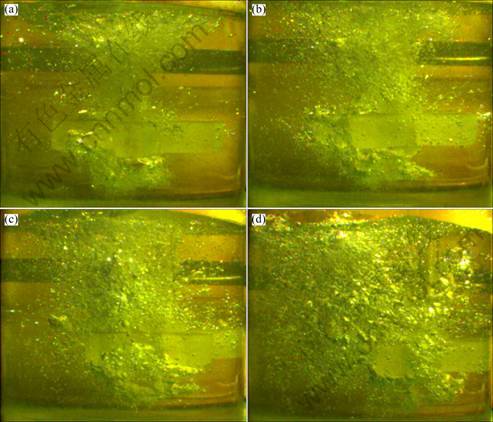
Fig. 7 Effect of eccentricity (e) on bubble dispersion and disintegration: (a) e=0.092; (b) e=0.185: (c) e=0.277; (d) e=0.370
Injected bubbles shown in Figs. 7(a) and (b) could not disperse widely in the bath. When the eccentricity is small, a stable horizontal tangential flow develops and a vortex is formed around or near the impeller shaft. The bottom of the vortex almost reaches the impeller. As a result, bubbles gather in the neighbor of the vortex and leave quickly into the atmosphere. Hence the gas-liquid contact is insufficient. Figures 7(c) and (d) show bubble dispersion phenomena for larger eccentricity. It is seen that the bubble dispersion is improved. As stated in the former section, the main reason for this improvement is that as the impeller shaft is more distant from the vessel center, the distance from the impeller shaft to the vortex is larger.
3.5 Effect of immersion depth of nozzle on bubble disintegration
Figure 8 shows the experimental results with changing the nozzle immersion depth. The eccentricity of the impeller shaft was 0.370. The gas flow rate was 4.5 m3/h and the rotation speed was 1.67 r/s. Since the injected bubbles hardly disperse below the impeller, the nozzle has to be immersed deeper in the bath for expanding the bubble dispersion zone. It is seen from Figs. 8(a) and (b) that on the opposite side of the impeller placing (on the right side of the photos), bubbles hardly disperse and the bubble density is very low. This is due to the fact that the vortex center is nearer to the vessel center when the nozzle immersion depth is smaller (Fig. 5) and the strong macroscopic flow cannot reach the wall of the opposite side of the impeller placing. The deeper the nozzle immersion depth is, the wider the bubble dispersion in the bath is, as shown in Figs. 8(c) and (d).
3.6 Relation between volume-surface mean diameter and rotation speed
The size of bubbles is measured using an image-processing software. The volume-surface mean diameter calculated from the measured bubble size distribution is plotted against impeller rotation speed in Fig. 9.
From Fig. 9, it can be seen that the size of bubbles in liquid increases with increasing gas flow rate or more accurately with increasing superficial gas velocity, which is defined as gas flow rate divided by the cross sectional area of gas-liquid two-phase flow zone. The reason is that at larger superficial gas velocity bubble coalescence takes place more frequently [5]. However, although the bubble diameter tends to increase with gas flow rate, the increase in bubble diameter becomes smaller at higher impeller rotation speed because the strong turbulence field prevents the bubble coalescence. This feature is advantageous for the gas–liquid contact at very large gas injection rates in gas injection refining processes.

Fig. 8 Effect of nozzle immersion depth on bubble disintegration and dispersion: (a) 0.193 m; (b) 0.223 m; (c) 0.253 m; (d) 0.283 m
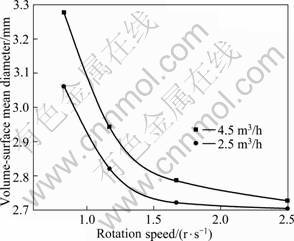
Fig. 9 Relation between volume-surface mean diameter and rotation speed
3.7 Gas injection from immersion lance
In the experiments shown so far, air was injected horizontally from a four-hole nozzle installed at the end of the impeller shaft. Additional experiments were made using an immersion lance for gas injection. Gas was injected horizontally from a hole at the side of the immersion lance (Fig. 10(a)) or vertically upward from a hole drilled at the top of the immersion lance (Fig. 10(b)). The gas flow rate was 2.3 m3/h and the rotation speed was 2.5 r/s. The positions of the immersion lance and the impeller in the bath were written in the figure. The experimental results are shown in Fig. 11. Figures 11(a) and (b) indicate that the direction of gas injection and the nozzle structure largely affect the bubble disintegration and dispersion in the bath. Figure 11(a) shows the experimental result for the horizontal gas injection from a one-hole immersion lance.
Upon reaching the impeller, the bubbles disintegrate fairly well, although some large bubbles are found in the bath. The large bubbles are those detached from the side of the injected jet before colliding with the impeller. The bubble density is high in the vessel center, but low near the vessel wall. It is to be noted that the injected bubbles drift toward the vessel center owing to the eccentric stirring. Figure 11(b) shows the picture for upward gas injection from a one-hole immersion lance which is located beneath the impeller. The vertical upward gas injection creates a strong upward bubble flow, so that the bubbles cannot spread radially. Figure 11(b) clearly shows that the bubbles pass through the limited space between the blades. The vertical upward gas injection causes maldistribution of bubbles, and large bubbles are observed in Fig. 11(b).

Fig. 10 Sketch of gas injection from immersion lance: (a) Horizontal injection; (b) Vertical upward injection
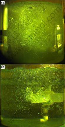
Fig. 11 Bubble dispersion under different gas injection mode: (a) Horizontal injection; (b) Vertical upward injection
4 Application of mechanical stirring to gas injection refining
Application of the eccentric stirring to gas injection refining requires comprehension of the flow phenomena. As shown in Fig. 4, however, the flow phenomena under the eccentric stirring are very complex and depend on the refining vessel size and the operating conditions. At present, we cannot give the guiding principle of design of gas injection refining processes.
Establishment of highly efficient gas injection refining processes is discussed qualitatively in the following.
The shear stress field and the vortex formation in the bath have crucial effects on the bubble disintegration and wide dispersion in the bath.
1) The bubble disintegration mainly proceeds in the strong shear stress field near the impeller. The shear stress field is governed by the Reynolds number under fulfillment of the geometric similarity condition. Therefore, the Reynolds number can be used in scaling-up of the refining process. Here it is to be noted that there exists the optimum impeller rotation speed, which depends on the vessel size, impeller structure and size, and immersion depth and eccentricity of the impeller. A low rotation speed results in the formation of a weak shear stress field, which cannot disintegrate the bubbles effectively. On the other hand, at too high rotation speed the horizontal tangential flow becomes too strong. Then the injected bubbles can disperse only locally near the center of the flow and the bubble disintegration cannot proceed sufficiently.
2) The distance from the vessel center to the impeller shaft or from the vortex center to the impeller should be large, so that the injected bubbles can travel far for wide dispersion in the bath. The position of the vortex center depends on the similar factors to the shear stress field. Again there exists the optimum impeller rotation speed. At a low impeller rotation speed, the macroscopic flow in the bath is weak and the injected bubbles cannot disperse widely in the bath. If the rotation speed is too high, a very large vortex is formed near the impeller. In this case, the bubble disintegrated near the impeller takes shortcut to the vortex and cannot travel far in the bath.
It is demonstrated that under the present experimental conditions, the bubble disintegration and wide dispersion in the bath can be achieved at an impeller rotation speed between 1.67 and 2.5 r/s. This rotation speed is almost the same as that in the KR method used for hot metal desulfurization and much lower than that in the aluminum refining process. Thus, the present eccentric mechanical stirring with unidirectional impeller rotation is suited to the gas injection refining operated at high temperatures, because the impeller rotation speed should be as low as possible.
The fluid flow analysis of the eccentric mechanical stirring is required to design highly efficient gas injection refining processes. In particular, we need knowledge on the shear stress field around the impeller blades and the location of the vortex formation, which will be reported in a subsequent paper.
5 Conclusions
Water model experiments on gas injection were made using eccentric mechanical stirring for developing highly efficient gas injection refining processes. In the experiments, the impeller was set distant from the vessel center and rotated unidirectionally. Air was injected from a nozzle installed at the end of the impeller shaft or from an immersion lance, and bubble disintegration and dispersion in the bath were investigated. The following conclusions were obtained.
1) In eccentric stirring, a vortex is formed distant from the impeller. The small bubbles disintegrated near the impeller move in the direction to the vortex keeping up with the macroscopic flow induced by the stirring. Thus, the small bubbles can disperse widely in the bath, the bath surface is not wavy and splash formation is reduced.
2) Under the present experimental conditions, the shear stress field around the impeller is stronger at higher impeller rotation speed, so that the bubble disintegration proceeds more effectively.
3) The vortex is more distant from the impeller at larger eccentricity and immersion depth of the impeller. In this case, the relative velocity between the impeller and the liquid surrounding the impeller becomes large, and makes the shear stress field strong. In addition, the radial liquid flow discharging from the space between the impeller blades and the circulating flow is strengthened. Consequently, the bubble disintegration and wide dispersion in the bath proceed, and mixing of the bath is intensified.
References
[1] RODRIGUES R T, RUBIO J. New basis for measuring the size distribution of bubbles [J]. Minerals Engineering, 2003, 16(8): 757-765.
[2] FAROOK U, ZHANG H B, EDIRISINGHE M J. Preparation of microbubble suspensions by co-axial electrohydrodynamic atomization [J]. Medical Engineering & Physics, 2007, 29(7): 749-754.
[3] RENSEN J, LUTHER S, de VRIES J. Hot-film anemometry in bubbly flow (I): Bubble–probe interaction [J]. International Journal of Multiphase Flow, 2005, 31(3): 285-301.
[4] SADA E. Gas absorption in bubble-dispersed phase [J]. Progress in Chemical Engineering, 1969, 3: 83-111.
[5] KOIDE K. Characteristics of bubble column and aerated stirred tank [J]. Progress in Chemical Engineering, 1982, 16: 58-76.
[6] SZEKELY A G. The removal of solid particles from molten aluminum in the spinning nozzle inert flotation process [J]. Metall Trans B, 1976(7): 259-270.
[7] LIU Y, SANO M, ZHANG T A, WANG Q, HE J C. Intensification of bubble disintegration and dispersion by mechanical stirring in gas injection refining [J]. ISIJ International, 2009, 49(1): 17-23.
[8] LIU Y, SANO M, WANG Q, IHANG T A, HE J C. Mechanical stirring for gas injection refining in iron and steel making (1)—Intensification of bubble disintegration [C]//ISIJ Meeting. Japan, 2007, 20(4): 48.
[9] NOMURA T, IGUCHI M. Effects of mechanical offset agitation on dispersion of low density particles in cylindrical bath [J]. Tetsu-to-Hagane, 2002, 88: 1-7.
[10] LIU Y, ZHANG T A, SANO M, WANG Q, REN X D, HE J C. Bubble disintegration and dispersion by eccentric mechanical stirring in gas injection refining for iron and steel making [C]//The Third Baosteel Academic Conference. Shanghai, China, 2008: B65-B67.
[11] LIU Y, SANO M, WANG Q, ZHANG T A, HE J C. Mechanical stirring for gas injection refining in iron and steel making (2)—Enhancement of absorption of injected gas [C]//ISIJ Meeting. Japan, 2007, 20(4): 49.
[12] LIU Y, SANO M, WANG Q, ZHANG T A, HE J C. Mechanical stirring for gas injection refining in iron and steel making (3)—Eccentric mechanical stirring for bubble disintegration [C]//ISIJ Meeting. Japan, 2008, 21(1): 7.
[13] LIU Y, SANO M, WANG Q, ZHANG T A, HE J C. Mechanical stirring for gas injection refining in iron and steel making (4)—Perforated blade impeller for bubble disintegration and dispersion [C]//ISIJ Meeting. Japan, 2008, 21(1): 8.
[14] LIU Y, SANO M, ZHANG T A, HE J C. Analysis of gas utilization efficiency in injection refining process [C]//ISIJ Meeting. Tokyo, Japan, 2009: 166.
[15] LIU Y, SANO M, WANG Q, ZHANG T A, HE J C. Physical simulation on desulfurization by single blow grain Mg [J]. Journal of Northeastern University, 2006, 27(S2): 100-103. (in Chinese)
[16] LIU Y, ZHANG T A, ZHAO Q Y, WANG S C, REN X D, DOU Z H, HE J C. Experimental research on gas holdup in bubble disintegration process [J]. The Chinese Journal of Process Engineering, 2009, 9(s1): 97-101. (in Chinese)
[17] LIU Y, ZHANG T A, ZHAO H L, WANG S C, DOU Z H, JIANG X L, HE J C. Study on absorption of CO2 bubble disintegration in NaOH solution [J]. The Chinese Journal of Process Engineering, 2009, 9(s1): 185-188. (in Chinese)
[18] LIU Y, ZHANG T A, DU J R, WANG S C, DOU Z H, JIANG X L, HE J C. Numerical simulation of gas bubble disintegration and dispersion process in liquid [J]. The Chinese Journal of Process Engineering, 2009, 9(s1): 400-404. (in Chinese)
刘 燕1, 张廷安1, 佐野正道2, 王 强1, 任晓冬1, 赫冀成1
1. 东北大学 材料与冶金学院 多金属共生矿生态化利用教育部重点实验室,沈阳 110006;
2. 日本 名古屋大学,464-8603
摘 要:在喷气精炼过程中,气泡的分散和细化是提高精炼效率的必要条件。在水模型实验中应用了单向的偏心搅拌模式来寻找最佳的气泡微细化条件。影响气泡微细化的因素有:搅拌模式、偏心度、搅拌转速、喷嘴结构、喷嘴的浸入深度以及气体流量。气体的喷入方式包括两种,一是从搅拌桨下方的喷嘴中直接喷入,二是从一个位于搅拌桨下方的弯管中喷入。在偏心搅拌模式下,漩涡远离了搅拌桨的轴心,小气泡产生于搅拌桨附近的强湍流或高剪切应力场中,随着机械搅拌产生的宏观流向漩涡方向移动。因此,单向的偏心搅拌模式能促进气泡在溶池内的细化和分散。
关键词:喷气精炼;偏心搅拌;单向转动;气泡分散;气泡细化;宏观流
(Edited by YUAN Sai-qian)
Foundation item: Projects (50974035, 51074047) supported by the National Natural Science Foundation of China; Project (20090407) supported by the Doctoral Fund of Ministry of Education, China; Project (200921007) supported by Liaoning Key Science and Technology, China
Corresponding author: ZHANG Ting-an; Tel: +86-24-83681563; E-mail: shanqibao2000@163.com
DOI: 10.1016/S1003-6326(11)60947-3

