AZ31þ�Ͻ�400 ��C������֮����Ԫ��֤����
��Դ�ڿ����й���ɫ����ѧ��(Ӣ�İ�)2013���11��
�������ߣ������� ������
����ҳ�룺3372 - 3382
Key words��AZ31 magnesium alloy; constitutive law; finite element verification
ժ Ҫ��������������Ϸ���������AZ31B-H24þ�Ͻ�ĵ����������飬��Բ�����400 ��C�¶��£�Ӧ���� =10-5-10-2 s-1��Χ֮Ӧ����Ӧ���ϵ���ߣ��ҳ�һ����Ӧ�䡢Ӧ����Ϊ������Ӧ��������ʽ֮����ģ�ͣ�������ģ�Ͳ�������Ԫ(FEM)����һ��������ֵ����ģʽ������õ����������飬����֤��ɿ��ԡ�����Ԫ����(FEA)ʱ�Թ�����ѧ�ĵ�-������������������������ݻ���Ϊ��Ӧ������-Ӧ������֮��ϵ�����������ʾ��FEA�뵥�����������Ӧ����Ӧ���ϵ���ߣ��ڸ����ν��ϣ����߽Ծ����൱�������Ǻ��ԣ���ʵ����FEA�ڼ���Ӧ��״̬��֮�˼��ı�����״�����߽�����൱�ӽ������IJ��Դ�FEM����ģʽԤ��̶�����֮�������참�����Ըò��ϵĴ��Ƴ���������з��棬�������֤�˱���������ı���ģ��ӵ�г����Գ�����ѧ������ʵ���ԡ����Ķ�AZ31þ�Ͻ�֮��������ѧ�����ṩ��һ����ֵ����ģʽ֮�ο���
Abstract: A constitutive law is offered for an AZ31B-H24 Mg alloy within a strain rate range of 10-5-10-2 s�C1 at a temperature of 400 ��C. The constitutive law, which is developed by curve fitting the tensile tests data, is expressed as a flow stress function of strain and strain rate. Furthermore, the constitutive law is embedded into a proper FE model to simulate the tensile experiments for the purpose of verifying reliability, where the incremental stress-strain relationships are calculated by an elastic-plastic theory in the finite element analysis (FEA). The results show that the stress-strain characteristics and the final deformed shapes in the FEA agree well with the experiments. In addition, the predicting analysis of constant-velocity stretch conditions and the verification of a free bulge forming experiment show that the proposed FE model is practicable for mechanical analysis on superplastic forming problems. A selective numerical method is offered for advanced superplastic analysis on AZ31 Mg alloys.
Trans. Nonferrous Met. Soc. China 23(2013) 3372-3382
Shih-Tsung TSENG, Hsuan-Teh HU
Department of Civil Engineering, National Cheng Kung University, Tainan 701, Taiwan, China
Received 2 February 2013; accepted 15 May 2013
Abstract: A constitutive law is offered for an AZ31B-H24 Mg alloy within a strain rate range of 10-5-10-2s�C1 at a temperature of 400 ��C. The constitutive law, which is developed by curve fitting the tensile tests data, is expressed as a flow stress function of strain and strain rate. Furthermore, the constitutive law is embedded into a proper FE model to simulate the tensile experiments for the purpose of verifying reliability, where the incremental stress-strain relationships are calculated by an elastic-plastic theory in the finite element analysis (FEA). The results show that the stress-strain characteristics and the final deformed shapes in the FEA agree well with the experiments. In addition, the predicting analysis of constant-velocity stretch conditions and the verification of a free bulge forming experiment show that the proposed FE model is practicable for mechanical analysis on superplastic forming problems. A selective numerical method is offered for advanced superplastic analysis on AZ31 Mg alloys.
Key words: AZ31 magnesium alloy; constitutive law; finite element verification
1 Introduction
The most attractive characteristic of Mg is that it exhibits the lightest density (1.738 g/cm3) among metal materials, which is about a quarter of iron (7.87 g/cm3), and two third of that of aluminum (2.7 g/cm3) [1]. Components that are made of Mg alloys have better characteristics with regard to high specific strength and stiffness, good casting ability, machinability, and dimensional stability, high recyclability, and superior damping capacity [2]. These advantages make Mg and its alloys increasingly play an important role in automotive, aircraft, and 3C products [3-5].
Due to the intrinsic hexagonal close-packed (HCP) crystallographic structure of Mg alloys, a limited activation of slip planes at room temperature is available, so they exhibit only limited ductility and accommodation ability. This obviously limits the engineering applications of Mg alloys. Mg alloys are much more workable at elevated temperatures, as additional slip systems become available [6]. AZ31 alloy is a commercially available commonly used Mg alloy and has been proven to have a good superplastic property at a temperature range of 200-450 ��C [7-10]. Other than casting, the typical wrought forming processes that utilize the superplastic characteristic of Mg alloys encompass extrusion, rolling of sheet and plate, forging, stamping and blowing processes [3]. Superplastic forming (SPF) is a near-net-shape forming process that permits parts with complex shapes to be formed in a single formation operation, and it has precise accuracy with regard to dimensions. Furthermore, the cost of manufacturing a structure using SPF can be 50% less than a structure assembled from numerous parts and fasteners. However, SPF processes require an inefficient amount of trial and error in regard to deciding the temperature and pressure parameters to form a suitable part [11]. The challenge is to obtain a systematic and more efficient method that can develop optimum forming parameters to reduce the formation time and maintain the integrity of the formed part. Therefore, a number of numerical analyses have been developed, but the finite element method (FEM), due to its generality, has emerged as the most potent technique for modelling SPF processes.
A material model that can precisely characterize a material��s behavior is a prerequisite and key challenge for a reliable mechanical FEA. The SPF process for AZ31 mg alloys is a deformation process which takes place at elevated temperatures, and the flow stress is closely dependent on parameters related to strain, strain rate, temperature, activation energy, the strain hardening coefficient, and the strain rate sensitivity index. These parameters finally reflect the trend upon a material��s constitutive stress-stain relationship. There are two viewpoints that are used to describe the constitutive law of AZ31 Mg alloys at elevated temperatures. One is based on a microstructure deformation mechanism. This method builds up the evolution rules of parameters which affect the constitutive law based on mathematically modelling the texture changes in grain size, void ratios, crystal lattice, dynamic recrystallization and slip and twinning systems. Then, the constitutive law is assembled with these rules. The other is based on describing the macroscopic mechanical behavior of deformation i.e., the flow stress curve. This method directly establishes the evolution rules for parameters that affect stress-strain relationships based on a regression analysis of experimental data [12]. Among them, the method based on the microstructure��s viewpoint has to determine the texture change mechanisms that affect the parameters of the constitutive law; then, tests must be designed to quantify and develop the evolution rules, which are finally assembled to form the constitutive law. In this field, LIU et al [12], ABU-FARHA and KHRAISHEH [13], ZHANG et al [14], WALDE and RIEDEL [15], and CHOI et al [16] built some constitutive models for AZ31 Mg alloys, and each has an applicable range of temperature and strain rate under either tensile or compressive conditions. However, the involved microstructure mechanisms that lead to material deformation may be multiple and may also complicatedly interact with each other. Whether the constitutive law that considers the primary texture mechanisms is reliable or not has to be verified by comparing the stress-strain relationships between the building model and the experimental results. On the other hand, the constitutive law developed based on the macroscopic viewpoint mostly uses the uniaxial stress-strain data of tensile or compressive tests. In this method, tests are designed to quantify the influence of parameters on stress-strain relationships, and then the results are transformed into mathematical evolution rules through regressive analyses. This method is comparatively convenient and controllable since the evolution rules of parameters directly feed-back their effects on the flow stress trends. In this manner, WANG et al [17], ZHANG et al [18], TAKUDA et al [19,20], and NGUYEN et al [21] developed several flow stress equations as the constitutive law of AZ31 Mg alloys, and each also has its own applicable requirements. Among these, Refs. [12,13,17-20] only compared the consistency of stress-strain relationships between their models and their experimental results; however, they didn��t embed their models into any FE simulation to verify their reliability. NGUYEN et al [21] used the least squares curve fitting method to establish a constitutive model of an AZ31B Mg alloy, but his model failed to characterize the softening behavior of the material.
Before a constitutive law of superplastic materials such as AZ31 Mg alloy is applied to a mechanical simulation of manufacturing processes, it is necessary to perform the FEA, which simulates the original uniaxial test for the purpose of verifying reliability. In this work, a constitutive law for an AZ31B-H24 Mg alloy was developed through the use of curve fitting the uniaxial tensile test data that was performed by ABU-FARHA and KHRAISHEH [8]. The built constitutive law was embedded in an FE model to formulate the stress-strain relationships of the AZ31B-H24 Mg alloy. During the FEA, the mechanical plastic flow evolution was formulated using an elastic-plastic model, which calculated the elastic behavior using Hooke��s law and the subsequent work hardening behavior by combining the associated von-Mises flow rule with the isotropic hardening rule. The aim of this work is to develop a reliable constitutive law of an AZ31B-H24 Mg alloy and to construct an adequate FE model for the purpose of verifying a specific stress-strain progress of a material. Moreover, some additional constant-strain-rate and constant-velocity stretching cases that were not carried out by the uniaxial tensile experiments as well as a free bulge forming experiment were also simulated to prove the practicability of the proposed constitutive law.
2 Geometry of uniaxial tensile test samples
The presented FE model was verified with the tensile test experiments conducted by ABU-FARHA et al [8,22] on an AZ31B-H24 Mg alloy. High temperature uniaxial tensile tests were carried out using the INSTRON 5582 universal testing machine, which was equipped with an electrical resistance heating chamber (furnace) that provides a maximum temperature of 610 ��C and with a 5 kN capacity load cell that was used for load measurements. The material used in the experiments was commercially available AZ31B-H24 Mg alloy sheets, with a thickness of 3.22 mm and an average initial grain size of about 5 ��m. The sheets were used to prepare the tensile test samples into the shape of a dog bone, whose middle gauge region had an approximate cross section of 6.35 mm��3.22 mm and a length of 19.05 mm. The constant-strain-rate uniaxial tensile tests were conducted within a forming temperature range of 325-500 ��C, in 25 ��C increments, where the true strain rate varied between 2��10�C5 and 10�C2 s�C1. However, only the datum for 400 ��C, as an optimum superplastic formation temperature for the AZ31 Mg alloy [13], is adopted to form the constitutive law in this study. A constant-strain-rate test considers the total length of a tensile sample during the test, and it controls the stretching velocity to deform a sample under a constant strain rate status. Hence, the stretching velocity is a function of testing time, the sample��s initial length and the controlled strain rate. This velocity function can be calculated first and set up into the testing machine��s auto control system. The stress-strain relationships of the nine experimental constant-strain-rate tests are shown in Fig. 1, which indicates that the ductility increases with lower strain rates, and the corresponding final deformed samples are depicted in Fig. 2.

Fig. 1 Stress-strain characteristics of tensile tests for AZ31B-H24 magnesium alloy under various constant-strain- rate conditions at 400 ��C (Reproduced with permission from Ref. [22]. 2007 American Institute of Physics)
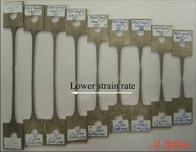
Fig. 2 Photograph of ultimately deformed tensile test samples for AZ31B-H24 magnesium alloy under various constant- strain-rate conditions at 400 ��C (Reproduced with permission from Ref. [8]. 2007 ASM International)
3 Constitutive law
Figure 1 represents the experimental data at a temperature of 400 ��C. If the effect of temperature is not included, the major macroscopic factors that affect the flow stress are strain and strain rate. As shown in this figure, the stress increased with larger strain rates at the same strain, and the ultimate fracture strain decreased with a larger strain rate, in which the characteristic became more brittle; moreover, a different degree of strain hardening or softening behavior was exhibited in every stress-strain curve. In this work, we analyzed the stress-strain relationships in Fig. 1 based on curve fitting methods to develop the constitutive law, which was expressed as a flow stress function of strain and strain rate. The applicable range of the strain rate within the constitutive law was varied between 10�C5 and 10�C2 s�C1 and then the developed constitutive law was verified by following the FEA on the tensile experiments, which were mentioned in Section 2. As a result, the developed constitutive law of flow stress equations is expressed as the following ��-transformed polynomials:
 (1)
(1)
where ��, �� and  are variables of true stress, true strain and true strain rate, respectively; ln �� represents the natural logarithm of ��; constant
  denotes the value of initial yielding stress for each corresponding strain rate condition in Fig. 1. Parameters
  ,
,  ,
,  obtained by curve fitting methods are all functions of the strain rate and can be expressed as follows:

 (2)
(2)
 (3)
(3)

 (4)
(4)
where  is the natural logarithm of , and exp() denotes the exponential function to the power of .
4 Incremental stress-strain relationships
The materials studied in this work were AZ31B-H24 Mg alloy plates manufactured using a rolling process, which exhibited an initial anisotropy between the RD (rolling direction) and the TD (transverse direction) at room temperature. However, it has also been observed that this anisotropic characteristic decreases constantly with rising temperature and becomes unobservable at 250 ��C [8,23]. Since the proposed constitutive law of the AZ31B-H24 Mg alloy would be verified by FE simulation on tensile tests at a temperature of 400 ��C in this study, we assumed the material to be homogeneous and isotropic for the subsequent numerical analyses. Hence, the mechanical theory chosen to calculate the incremental stress-strain relationships was an elastic-plastic model, for which the elastic behavior was formulated using Hooke��s law, and the work hardening plastic stress-strain relationships were calculated by combining the flow rule associated with the von Mises quadratic yield criterion with the isotropic hardening rule. According to the theory of plasticity, the relative equations of the elastic-plastic model can be derived as follows [24].
The total strain increment is decomposed into two parts,
 (5)
(5)
where the elastic strain increment,  , is related to the stress increment; d��ij, by the generalized Hooke��s law as
 (6)
(6)
while Cijkl is the tensor of the elastic modulus. For a linear-elastic isotropic material, Cijkl can be expressed in terms of the two elastic constants: shear modulus, G, and Poisson ratio, v:
 (7)
(7)
The plastic strain increment,  , can be generally expressed by a nonassociated flow rule in the form:
 (8)
(8)
where d�� is a positive scalar factor of proportionality, which is nonzero only when plastic deformations occur; g is known as the plastic potential function. The equation  =constant defines a surface of plastic potential in a nine-dimensional stress space. When the yield function and the plastic potential function coincide, f=g; the plastic flow equations can be expressed as follows:
 (9)
(9)
Equation (9) is called the associated flow rule because the plastic flow is associated with the yield criterion. The loading surface, which defines the boundary of the current elastic region, is the subsequence yield surface for an elastoplastically-deformed material under combined states of stress, and it can generally be written as
 (10)
(10)
The size of the yield surface is governed by the hardening parameter k2 expressed as a function of ��p, called the effective strain. Hence, the parameter k2 depends upon the plastic strain history. The function  defines the shape of the yield surface. Moreover, for a work hardening material, a hardening rule to describe the rule for the evolution of the loading surface is necessary. Since we assumed the analyzed material to be isotropic, we took the von Mises yield function as the plastic potential and the isotropic hardening rule, which expanded the initial yield surface uniformly without distortion and translation, as the evolution of the loading surface. When the von Mises yield criterion is used, we obtain
 (11)
(11)
with J2 expressed in the following as the invariant of the stress deviator tensor:
J2=sijsij/2 (12)
Then Eq. (10) becomes
 (13)
(13)
where sij denotes the stress deviator tensor defined by subtracting the spherical state of stress from the actual state of stress.
sij=��ij-��kk��ij/3 (14)
For practical use of the work-hardening theory of plasticity, the hardening parameters in the loading function have to be related to the experimental uniaxial stress-strain curve. To this end, the stress variable ��e, called the effective stress, and the strain variable ��p, called the effective strain, are introduced. Since the effective stress should reduce to stress ��1 in the uniaxial test, it follows that the loading function F(��ij) can be expressed as  . For the von-Mises material, , then
 (15)
(15)
and for the uniaxial test, ��e=��1 and ��2=��3=0. Therefore, n=2; C=1/3, and
 (16)
(16)
To replace the hardening parameter k with ��e, we substitute Eq. (16) into Eq. (13) and rewrite it as
 (17)
(17)
From the definition of the associated flow rule, g=f, the derivatives of g and f are found as
 (18)
(18)
Then from Eq. (9)  , where d�� is a scalar function to be determined by the consistency condition df=0 as
 (19)
(19)
with
 (20)
(20)
where the second order tensor Hkl associated with the yield function, f, is defined as
 (21)
(21)
The parameter Hp is a plastic modulus associated with the rate of expansion of the loading surface, and it can be defined as the slope of the uniaxial stress-plastic strain curve at the current value of ��e.
 (22)
(22)
For the F(J2, J3) material, such as the von-Mises material, which is pressure independent when plastic flow occurs, the effective plastic strain increment is defined as
 (23)
(23)
The strain history for the material is the record of the length of the effective plastic strain path:
 (24)
(24)
From the above equations, when the plastic flow occurs, the incremental stress-strain relationships can be derived as follows:

 (25)
(25)
 (26)
(26)
with
 (27)
(27)
In conclusion, the complete incremental stress- strain relationships for an elastic-plastic work-hardening material can be expressed as follows.
For  , and
, and  , the material is in a plastic loading state, and we have
  .
.  is given in Eq. (25) and Eq. (26).
For  , or ,
  , the material is in an unloading or neutral loading state, and we have
 is given in Eq. (7).
5 FE verification on uniaxial tensile test for constitutive law
5.1
FE model
In order to verify the reliability of the presented constitutive law of the AZ31B-H24 Mg alloy, numerical analyses were carried out by means of the finite element method in this study, whose results were verified by the uniaxial tensile experiments performed by ABU-FARHA and KHRAISHEH [8]. The FE simulation was performed using a commercial FE package, ABAQUS version 6.10. The constitutive law of Eq. (1) was embedded into a rate-dependent metal plasticity material model of ABAQUS, in which the elastic-plastic theory combined with the selective isotropic hardening rule could be included to evaluate the incremental stress-strain relationships. The constitutive stress, strain and strain rate data calculated from Eq. (1) could be input into a three-column table in the rate-dependent metal plasticity material model of ABAQUS. When the analysis begins, ABAQUS connects the data points with piecewise linear line segments to approximate the nonlinear stress-strain relationships of the material. The geometry, boundary conditions, and element distribution of the FE model used to simulate the uniaxial tensile tests are schematized in Fig. 3. The geometry constructed in the FE model only includes the gauge region with a cross section of 6.35 mm��3.22 mm and a length of 19.05 mm because it is the place used to define the stress and strain characteristics within the sample. The analyses were conducted with a three-dimensional FE simulation with an advantage of being able to clearly examine the stress and deformation conditions in the model. For the purpose of simulating the uniaxial tensile tests, the boundary conditions are described as follows: Ux=0 is applied to the ABCD plane; Uy=0 is applied to the AB and EF line segments; Uz=0 is applied to points A and E. In addition, the uniaxial constant-strain-rate stretch was simulated using a uniform x-direction stretching velocity, vx, on the EFGH plane. As time passed during the test, the total length of the tensile specimen became longer and longer; then the uniaxial stretching speed had to be quicker and quicker for the purpose of maintaining the strain rate with a constant value. As a result, the stretching velocity, vx, can be expressed as the following function of testing time, sample��s initial length and the controlled strain rate[25]:
 (28)
(28)
where L0=0.01905 m, is the initial length of the gauge region; denotes the value of the controlled strain rate; t is the testing time.

Fig. 3 Geometry, boundary conditions, and element distribution of finite element model for simulating uniaxial tensile test
Figure 3 also shows the mesh of the FE model, in which there was the three-dimensional second-order solid element, C3D20, which provided better accuracy for describing deformation compared with the first-order element. The ABAQUS built-in C3D20 element is a 20-node quadratic brick element, which has three degrees of freedom per node (displacements in x, y, and z directions). The cases studied here addressed the problem of a homogeneous and isotropic material experiencing uniform uniaxial velocity on its uniform cross section. According to the theory of continuum mechanics, the axial stresses and strains existing in elements throughout the model should be uniform; thus, there is no need to perform a convergent analysis on the element number of the model. However, we observed that the initial aspect ratio of the elements should be less than a maximum value of 4 in order to avoid a numerical error in the FE calculation. By arranging the number of the elements equal to 6, 2, and 1 corresponding to the x, y, and z directions, respectively, the initial aspect ratio of the elements in the whole model was 1.01. The Full Newton-Raphson iterative procedure embedded in ABAQUS was chosen to solve the iteration process and non-linear equations of motion in this study.
5.2 FEA results
The comparison of axial stress-strain relationships between the experimental results and numerical analyses is presented in Fig. 4. In this figure, the stress-strain curves of the nine experimental constant-strain-rate stretch cases were drawn with solid lines, where thicker and thinner lines were used to represent the corresponding experimental and FEA results, respectively.

Fig. 4 Comparison between FEA and experimental results for stress-strain characteristics of AZ31B-H24 magnesium alloy under various constant-strain-rate conditions
On the other hand, the broken lines in Fig. 4 predict other constant-strain-rate stretch conditions that were not carried out by the tensile tests. This figure shows that the FEA results were in good agreement with all nine experimental strain rate curves (=10-2-2��10-5 s�C1). Furthermore, the broken lines in Fig. 4 also show that the presented constitutive law has the ability to reasonably predict other stress-strain characteristics of strain rates =7��10-3, 3.5��10-3, 7��10-4, 3.5��10-4, 7��10-5, 3.5��10-5 and 1��10-5 s�C1, which make up for the lack of tensile experiments and prove that the proposed constitutive law is suited for a deformed strain rate range of 10-5-10-2 s-1. Figure 5 depicts the original undeformed as well as the deformed FE samples for the nine experimental constant- strain-rate cases when each analysis approximately reached its experimental ultimate strain state. By comparing Fig. 5 with the corresponding experimental results in Fig. 2, the deformed shape, length, width, and thickness of the gauge section in the experimental samples agree well with the results of the FE simulation. The axial true stress contour defined by different colors and the true strain value at different stages of deformation in the case of =5��10-5 s�C1 are shown in Fig. 6, which represents the deformation stages of analysis from the beginning until the experimental ultimate strain state is reached. In this figure, the grade of axial true stress contour is represented by the different colors at the lower left corner. There are four samples in Fig. 6, and the undeformed sample on the far right indicates the initial condition of the analysis, in which the stress and strain values are both equal to zero and in which the zero stress is located at a blue color contour range of 0-1.00 MPa. The second blue sample from the right in Fig. 6 indicates that the analysis approximates to the initial yielding stage with a strain value of 0.006 as well as a stress value of 1.612 MPa, which is located at a blue color contour range of 1.00-2.00 MPa, can be determined by the corresponding stress-strain curves of FEA results shown in Fig. 4. Similarly, the third red and the fourth green samples from the right in Fig. 6 reveal that the analysis is demonstrating the corresponding maximum ultimate stress state (��=11.659 MPa, and ��=1.0), and the ultimate experimental strain state (��=7.529 MPa, and ��=1.70), respectively. Since the deformation histories of other constant-strain-rate FE analyses are similar to those depicted in Fig. 6, we only use them for the emblematic presentation. Figure 6 reveals that the axial stresses and strains are uniformly distributed in the model at every deformation stage. The reason for this was mentioned in Section 5.1 in which we described the problem type analyzed in the FEM as a uniform uniaxial velocity acting on a uniform cross section of a homogeneous and isotropic material. Hence, the studied samples became uniformly longer and thinner until the analysis approximately reached the experimental ultimate fracture strain state. These results satisfy the need for good agreement with the complete stress-strain characteristics between the FEA and the experiments. Hence, the presented constitutive law and the FE model are confirmed to be adequate for simulating the uniaxial tensile tests.

Fig. 5 Original undeformed as well as deformed FE samples for nine experimental constant-strain-rate cases when each analysis approximately reached its experimental ultimate strain state
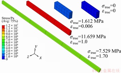
Fig. 6 Stress and strain history of FEA at different stages of deformation in the case of strain rate equal to 5��10-5
6 FE simulation on constant-velocity stretch cases and bulge forming experiment
In addition, for the purpose of verifying the adaptability of the constitutive law on time dependent strain rate problems, some predicting simulations were performed here on the uniaxial constant-velocity stretch condition, which is often seen in uniaxial tensile tests. Due to the fact that the total length of the tensile specimens became longer and longer, the strain rate value gradually decreased during the constant-velocity stretch process. In order to simulate this problem, the uniform x-direction stretching velocity, vx, on the EFGH plane in Fig. 3 had to be set with a constant value. There were five constant velocity values (vx=2��10-4, 1��10-4, 5��10-5, 2��10-5, and 1��10-5 m/s) chosen for the predicting analyses, and the corresponding FEA results for the stress-strain curves are shown in Fig. 7, which shows that all five constant-velocity stress-strain curves crossed the experimental constant-strain-rate curves. When the constant-velocity analysis began, the strain increased with a gradually decreased value of strain rate, and this phenomenon can also be observed from the intersecting trend between the constant-velocity curves and the constant-strain-rate curves in Fig. 7. These results show that the presented constitutive law is adaptable for mechanical analysis on time-dependent strain rate problems for AZ31 mg alloys.
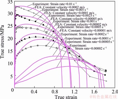
Fig. 7 Comparison between FEA of constant-velocity conditions and experimental results of constant-strain-rate conditions for uniaxial stress-strain characteristics

Fig. 8 Schematic diagram of free bulge forming of circular sheet into hemisphere (Modified from ABU-FARHA et al [26])

Fig. 9 Pressure-time profile for free bulge forming experiment (Modified from ABU-FARHA et al [26])
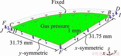
Fig. 10 Geometry and boundary conditions of FE model for simulating bulge forming experiment
Furthermore, the FE simulation on the free bulge forming experiment, which was conducted by ABU-FARHA et al [26] using the same AZ31B-H24 Mg alloy mentioned in Section 2, was also performed here to assess the practicability of the proposed constitutive law. A schematic diagram of the studied geometry is shown in Fig. 8, where p is the applied argon gas pressure with an electronically controlled pressure-time profile plotted in Fig. 9. The radius of an open die, which is used to allow for the free forming of a circular sheet into a hemispherical dome, is 31.75 mm. The thickness of the sheet is 1 mm. After the sheet was clamped onto the die, the whole setup was heated to 400 ��C, followed by 30 min of holding time to allow for thermal equilibrium, before the pre-selected pressure scheme was applied. The experimental bulge heights were 29.5 and 31.5 mm at the corresponding forming time equal to 1805 and 1888 s, respectively. The geometry and boundary conditions constructed in the FE model for simulating this bulge forming experiment are schematized in Fig. 10. This case exhibits biaxial mechanical symmetry, so only a quarter of a circle plate had to be analyzed in the FE model. The radius of the forming quadrant ABC was 31.75 mm, where the (gas) pressure loading with a pressure-time profile plotted in Fig. 9 was applied to the ABC plane. The boundary conditions are described as follows: x-direction and y-direction symmetry conditions were applied to the corresponding ADIF and AEJF plane, respectively; a fixed constraint was applied to the GHJI plane to simulate the clamped circumference. Figure 11 shows the mesh of the FE model, in which there were 1152 three-dimensional second-order tetrahedral elements, C3D10M. The ABAQUS built-in C3D10M element is a 10-node quadratic tetrahedral element, which has three degrees of freedom per node (displacements in x, y, and z directions). Since this analytic model also exhibits mechanical symmetry, the mesh was arranged to be symmetric to the central line of the whole quadrant. The ABAQUS/Explicit solver was chosen to integrate the equations of motion for this non-linear dynamic problem. The deformation history of FEA results are presented in Fig. 12 through the mirror function embedded in ABAQUS to display the symmetric deformation with respect to the ADIF and AEJF plane, so the entire hemispheric deformation can be shown for this biaxial symmetric FEA model. In addition, the experimental bulge deformation at 1805 s is also put in Fig. 12 for comparison. The bulge heights of FEA at 1805 and 1888 s were 29.22 and 31.54 mm, respectively, for which the corresponding errors were only 0.95% and 0.01% compared with the experimental results (29.5 and 31.5 mm). These results show that the presented constitutive law and FE model have good practicability for mechanical analysis on superplastic forming problems for AZ31 mg alloys.

Fig. 11 Element distribution of FE model for simulating bulge forming experiment

Fig. 12 Bulge forming deformation history of FEA as well as experimental result at 1805 s
7 Conclusions
The stress-strain relationships were analyzed based on curve fitting methods to develop a constitutive law, which was expressed as a flow stress function of strain and strain rate, for an AZ31B-H24 Mg alloy. The experimental stress-strain relationships were performed using the constant-strain-rate uniaxial tensile tests within a strain rate range of 2��10-5-10-2 s�C1 at a temperature of 400 ��C. The presented constitutive law was embedded into an FE model that simulated the tensile tests for the purpose of verifying reliability. The analyzed AZ31B-H24 Mg alloy at 400 ��C was assumed to be homogeneous and isotropic for the FE simulation, so the incremental stress-strain relationships were formulated using a 3D elastic-plastic model, which simulated the elastic response using Hooke��s law and the work hardening response using the flow rule associated with the von-Mises yield criterion combined with the isotropic hardening rule. The results showed the stress-strain relationships of the nine experimental constant-strain- rate stretch cases agree well with the FEA data, and the deformed shape, width, and thickness of the FEA also agreed well with the tensile test samples. These verifications confirm the reliability of the presented constitutive law and FE model, which can be used to analyze the mechanical behavior of AZ31B-H24 Mg alloy. Moreover, some constant-strain-rate cases which were not carried out by the tensile tests were also analyzed for supplements, where the results represented good reasonability and further expanded the applicable strain rate range of 10-5-10-2 s-1 for the proposed constitutive law. Finally, five uniaxial constant-velocity stretch cases and a free bulge forming experiment were simulated, and the results also showed good practicability for the proposed FE model. This work offers a selective numerical method for advanced mechanical superplastic analysis on AZ31 Mg alloys.
Acknowledgments
The authors would like to thank the anonymous (unknown) reviewers and the editor for their comments. Some of the materials presented in this paper were first published in the Journal of Materials Engineering and Performance, ASM International and the 10th ESAFORM Conference on Material Forming, American Institute of Physics. The authors are grateful for the publisher��s permission to reprint the materials here.
References
[1] DAVIS J R. ASM handbook Vol.02-properties and selection: nonferrous alloys and special-purpose materials [M]. Ohio: ASM International, 1993.
[2] EASTON M, BEER A, BARNETT M, DAVIES C, DUNLOP G, DURANDET Y, BLACKET S, HILDITCH T, BEGGS P. Magnesium alloy applications in automotive structures [J]. JOM: Journal of the Minerals Metals and Materials Society, 2008, 60(11): 57-62.
[3] EDGAR R L. Magnesium alloys and their applications [M]. Weinheim: Wiley-Vch Verlag Gmbh, 2000: 3-8.
[4] CLOW B B. Magnesium industry overview [J]. Advanced Materials and Processes, 1996, 150(4): 33-34.
[5] YANG Z, LI J P, ZHANG J X, LORIMER G W, ROBSON J. Review on research and development of magnesium alloys [J]. Acta Metallurgica Sinica, 2008, 21(5): 313-328.
[6] JANECEK M, KRAL R, DOBRON P, CHMELIK F, SUPIK V, HOLLANDER F. Mechanisms of plastic deformation in AZ31 magnesium alloy investigated by acoustic emission and transmission electron microscopy [J]. Materials Science and Engineering A, 2007, 462(1-2): 311-315.
[7] YANG H, HUANG L, ZHAN M. Coupled thermo-mechanical FE simulation of the hot splitting spinning process of magnesium alloy AZ31 [J]. Computational Materials Science, 2010, 47(3): 857-866.
[8] ABU-FARHA F K, KHRAISHEH M K. Mechanical characteristics of superplastic deformation of AZ31 magnesium alloy [J]. Journal of Materials Engineering and Performance, 2007, 16(2): 192-199.
[9] WATANABE H, TSUTSUI H, MUKAI T, ISHIKAWA K, OKANDA Y, KOHZU M, HIGASHI K. Superplastic behavior in commercial wrought magnesium alloys [J]. Materials Science Forum, 2000, 350-353: 171-176.
[10] EL-MORSY A W, MANABE K, NISHIMURA H. Superplastic forming of AZ31 magnesium alloy sheet into a rectangular pan [J]. Materials Transactions, 2002, 43(10): 2443-2448.
[11] BIELER T R, MISHRA R S, MUKHERJEE A K. Superplasticity in hard-to-machine materials [J]. Annual Review of Materials Science, 1996, 26: 75-106.
[12] LIU J, CUI Z S, LI C X. Modelling of flow stress characterizing dynamic recrystallization for magnesium alloy AZ31B [J]. Computational Materials Science, 2008, 41(3): 375-382.
[13] ABU-FARHA F K, KHRAISHEH M K. Analysis of superplastic deformation of AZ31 magnesium alloy [J]. Advanced Engineering Materials, 2007, 9(9): 777-783.
[14] ZHANG S R, PENG Y H, TANG W Q, LI D Y. The polycrystalline plasticity due to slip and twinning during magnesium alloy forming [J]. Acta Mechanica, 2010, 212(3-4): 293-303.
[15] WALDE T, RIEDEL H. Simulation of earing during deep drawing of magnesium alloy AZ31 [J]. Acta Materialia, 2007, 55(3): 867-874.
[16] CHOI S H, KIM D H, SEONG B S. Simulation of strain-softening behaviors in an AZ31 Mg alloy showing distinct twin-induced reorientation before a peak stress [J]. Metals and Materials International, 2009, 15(2): 239-248.
[17] WANG L Y, FAN Y G, HUANG G J, HUANG G S. Flow stress and softening behavior of wrought magnesium alloy AZ31B at elevated temperature [J]. Transactions of Nonferrous Metals Society of China, 2003, 13(2): 335-338.
[18] ZHANG X H, RUAN X Y, OSAKADA K. Forgeability of AZ31B magnesium alloy in warm forging [J]. Transactions of Nonferrous Metals Society of China, 2003, 13(3): 632-635.
[19] TAKUDA H, MORISHITA T, KINOSHITA T, SHIRAKAWA N. Modelling of formula for flow stress of a magnesium alloy AZ31 sheet at elevated temperatures [J]. Journal of Materials Processing Technology, 2005, 164: 1258-1262.
[20] TAKUDA H, FUJIMOTO H, HATTA N. Modelling on flow stress of Mg-Al-Zn alloys at elevated temperatures [J]. Journal of Materials Processing Technology, 1998, 80-81: 513-516.
[21] NGUYEN D T, KIM Y S, JUNG D W. Coupled thermomechanical finite element analysis to improve press formability for camera shape using AZ31B magnesium alloy sheet [J]. Metals and Materials International, 2012, 18(4): 583-595.
[22] ABU-FARHA F K, NAZZAL M A, KHRAISHEH M K. An experimental study on the stability of superplastic deformation of AZ31 Mg alloy [C]//10th ESAFORM Conference on Material Forming, Parts A and B. New York, 2007: 1289-1294.
[23] KAISER F, LETZIG D, BOHLEN J, STYCZYNSKI A, HARTIG C, KAINER K U. Anisotropic properties of magnesium sheet AZ31 [J]. Materials Science Forum, 2003, 419-422: 315-320.
[24] CHEN W F, HAN D J. Plasticity for structural engineers [M]. New York: J Ross Publishing, 2007: 232-280.
[25] GHOSH A K, HAMILTON C H. Mechanical behavior and hardening characteristics of a superplastic Ti-6Al-4V alloy [J]. Metallurgical Transactions A, 1979, 10(6): 699-706.
[26] ABU-FARHA F K, RAWASHDEH N A, KHRAISHEH M K. Superplastic deformation of magnesium alloy AZ31 under biaxial loading condition [J]. Materials Science Forum, 2007, 551-552: 219-224.
�����ϣ�������
�ɹ���ѧ ��ľ����ѧϵ��̨�� 701���й�̨��
ժ Ҫ��������������Ϸ���������AZ31B-H24þ�Ͻ�ĵ����������飬��Բ�����400 ��C�¶��£�Ӧ����=10-5-10-2 s-1��Χ֮Ӧ����Ӧ���ϵ���ߣ��ҳ�һ����Ӧ�䡢Ӧ����Ϊ������Ӧ��������ʽ֮����ģ�ͣ�������ģ�Ͳ�������Ԫ(FEM)����һ��������ֵ����ģʽ������õ����������飬����֤��ɿ��ԡ�����Ԫ����(FEA)ʱ�Թ�����ѧ�ĵ�-������������������������ݻ���Ϊ��Ӧ������-Ӧ������֮��ϵ�����������ʾ��FEA�뵥�����������Ӧ����Ӧ���ϵ���ߣ��ڸ����ν��ϣ����߽Ծ����൱�������Ǻ��ԣ���ʵ����FEA�ڼ���Ӧ��״̬��֮�˼��ı�����״�����߽�����൱�ӽ������IJ��Դ�FEM����ģʽԤ��̶�����֮�������참�����Ըò��ϵĴ��Ƴ���������з��棬�������֤�˱���������ı���ģ��ӵ�г����Գ�����ѧ������ʵ���ԡ����Ķ�AZ31þ�Ͻ�֮��������ѧ�����ṩ��һ����ֵ����ģʽ֮�ο���
�ؼ��ʣ�AZ31þ�Ͻ𣻱����ɣ�����Ԫ��֤
(Edited by Hua YANG)
Corresponding author: Hsuan-The HU; Tel: +886-6-2757575-63168; Fax: +886-6-2358542; E-mail: hthu@mail.ncku.edu.tw
DOI: 10.1016/S1003-6326(13)62877-0

