���������Ե�����ѡ���ۻ�Ti6Al4V�Ͻ�ĸ�ʴ��ĥ������
��Դ�ڿ����й���ɫ����ѧ��(Ӣ�İ�)2020���8��
�������ߣ����� ������ ���ľ� ���� ����� ������ ����Ƽ
����ҳ�룺2132 - 2142
�ؼ��ʣ�������ѡ���ۻ�����������TC4�Ͻ𣻸�ʴ��ĥ������
Key words��selective electron beam melting; micro-arc oxidation; TC4 alloy; corrosion; wear property
ժ Ҫ��Ϊ�˷�����������ѹ��Ti6Al4V(TC4)�Ͻ�ʴ��ĥ�����ܵ�Ӱ�죬�ֱ���400��420��450 V�Ե�����ѡ���ۻ�(SEBM)�Ʊ���TC4��Ʒ�������������洦���������������������ʱ����¶ȵ����ӣ�����̬���ѿ���TiO2��ת��Ϊ���ʯ��TiO2��MAOĤ������ò��Ҫ�dzߴ�ֲ����ȵĴ����ף�����450 V��ѹ�³������ƺ� >10 ��m�Ŀ�϶��MAOĤ�����ʩ�ӵ�ѹ������ء�MAOĤ����ʴ���ܺ�ĥ������������� �֡������׳ߴ�ֲ���Ĥ���йأ���MAO��ѹΪ420 Vʱ����ʴ�����ܶ���С(0.960��10-7 A/cm2)���迹���(7.17��105 ����cm2���� ��ʴ������ã���ͬ�غ������£�Ϳ���Ħ��������ĥ���������ڻ���ģ�����MAO ʩ�ӵ�ѹ�����ӣ�MAOĤ��ĥ�������ĥ��ĥ��ת��Ϊճ��ĥ����450 V��ѹʱճ��ĥ��Ӿ磬Ħ������Ҳ���Ϊ0.821��
Abstract: In order to analyze the effect of voltage during micro-arc oxidation (MAO) on corrosion and wear properties of Ti6Al4V (TC4), the MAO technology was employed to treat TC4 samples fabricated by selective electron beam melting (SEBM) at the voltages of 400, 420 and 450 V. The results show that the metastable anatase phase gradually transforms to rutile phase with oxidation time and temperature increasing. The surface morphology of coating contains numerous micropores with uniform size distribution. Cracks and pores over 10 ��m are found on MAO-TC4 sample with applied voltage of 450 V. The thickness of MAO coating is positively correlated with the voltage. The corrosion resistance and wear resistance are related to phase composition, micropore size distribution on the surface and film thickness. When the voltage is 420 V, the coating shows the smallest corrosion current density (0.960��10-7 A/cm2) and the largest resistance (7.17��105 ����cm2). Under the same load condition, the coating exhibits larger friction coefficient and wear loss than the TC4 substrate. With the increase of voltage, the wear mechanism of the coating changes from abrasive wear to adhesive wear, and the adhesive wear is intensified at applied voltage of 450 V, with a maximum friction coefficient of 0.821.
Trans. Nonferrous Met. Soc. China 30(2020) 2132-2142
Xin YANG1, Wan-lin WANG1, Wen-jun MA1, Yan WANG2, Jun-gang YANG1, Shi-feng LIU2, Hui-ping TANG3
1. School of Materials Science and Engineering, Xi��an University of Technology, Xi��an 710048, China;
2. School of Metallurgical and Engineering, Xi��an University of Architecture and Technology, Xi��an 710055, China;
3. State Key Laboratory of Porous Metal Materials, Northwest Institute for Non-ferrous Metal Research, Xi��an 710016, China
Received 9 January 2020; accepted 30 July 2020
Abstract: In order to analyze the effect of voltage during micro-arc oxidation (MAO) on corrosion and wear properties of Ti6Al4V (TC4), the MAO technology was employed to treat TC4 samples fabricated by selective electron beam melting (SEBM) at the voltages of 400, 420 and 450 V. The results show that the metastable anatase phase gradually transforms to rutile phase with oxidation time and temperature increasing. The surface morphology of coating contains numerous micropores with uniform size distribution. Cracks and pores over 10 ��m are found on MAO-TC4 sample with applied voltage of 450 V. The thickness of MAO coating is positively correlated with the voltage. The corrosion resistance and wear resistance are related to phase composition, micropore size distribution on the surface and film thickness. When the voltage is 420 V, the coating shows the smallest corrosion current density (0.960��10-7 A/cm2) and the largest resistance (7.17��105 ����cm2). Under the same load condition, the coating exhibits larger friction coefficient and wear loss than the TC4 substrate. With the increase of voltage, the wear mechanism of the coating changes from abrasive wear to adhesive wear, and the adhesive wear is intensified at applied voltage of 450 V, with a maximum friction coefficient of 0.821.
Key words: selective electron beam melting; micro-arc oxidation; TC4 alloy; corrosion; wear property
1 Introduction
Titanium alloys are widely and frequently used due to their high specific strength, corrosion resistance and excellent bio-compatibility [1-4]. Usually, Ti6Al4V (TC4) alloy is used in high value-added fields such as aviation, aerospace, bio-medicine and navigation industries as structure-function integrated material [5]. However, TC4 alloy has shortcomings such as low heat transfer coefficient and narrow thermal processing window. Therefore, it is difficult to prepare complex structures with micro-truss structure, porous three-dimensional network structure and thin-walled irregular parts of internal flow channel by traditional casting and forging processes [6-8]. Metal additive manufacturing (AM) makes it possible to design and accomplish near net forming of complex parts [9,10]. Selective electron beam melting (SEBM) is one of the most favored AM approaches in the manufacture of TC4 components [11].
SEBM technology enables to effectively avoid internal stress and cracks of metal parts during rapid cooling due to its high scanning power and high scanning rate [12]. In addition, this technology has the advantages of high overall precision of forming parts, high material utilization rate and low production time, and is one of the typical representatives of the powder bed additive manufacturing technology [13]. Its characteristic high-temperature self-tempering can homogenize the microstructure. MURR et al [14] found that the tensile strength of SEBM-TC4 is comparable to that of the wrought TC4. The lightweight design of porous Ti alloys prepared by SEBM technology has been widely used in the orthopedic implants, automotive, aerospace and other fields [15,16]. To date, existing SEBM-TC4 studies have been mainly focused on the mechanical properties [14,15]. Previous studies [17-20] have shown that surface defects are the main factors affecting the corrosion and wear properties of SEBM-TC4 alloys. TC4 can spontaneously form a stable passivation film in the air and solution, which plays a key role in the corrosion resistance of TC4. But, passivation films are easily destroyed, especially in salt solutions containing Cl- ions [21]. At the same time, due to the contact with harsh environment, the corrosion performance of oil and gas transportation pipeline is a key problem. The poor wear resistance of TC4 is another problem for its application in human implants. Due to wear, a large amount of Ti, Al and V debris is produced in the implant, which is easy to cause loosening of the implant, leading to the failure of implant implantation [7]. Thus, it is important to improve the corrosion resistance and wear properties of TC4 alloy. Traditional processing technologies such as machining and shot peening are not suitable for surface treatment of porous structures and complex shape parts, and chemical corrosion can destroy incompletely melted powder with surface depth of 0.5 mm, which is not suitable for surface modification of thin-walled parts. It has been demonstrated that micro-arc oxidation (MAO) post-treatment could improve the corrosion resistance and wear properties of Ti alloys [22]. Therefore, MAO was employed to treat the SEBM-TC4 alloy so as to improve its surface conditions and properties.
The MAO technology, also known as plasma electrolytic oxidation, is an environment-friendly surface modification technology that generates in-situ coating structures on lightweight metals, such as Al, Mg and Ti alloys. The micro-arc oxidation of Ti alloy is mainly caused by the in-situ reaction of Ti4+ ions and OH- ions in the electrolyte on the substrate surface forming TiO2 ceramic layer. The MAO oxide film exhibits good adhesion of B-F (base-film) interface, excellent chemical corrosion resistance, high wear resistance and temperature resistance [23]. The structure, phase compositions and mechanical properties of the oxide film can be tailored by MAO parameters. The main regulatory parameters of MAO are the current density, discharging time, input voltage, and electrolyte composition [24]. Studies have shown that the smooth, small-pore and uniform oxide films were obtained on Ti alloys during the discharging process in 10 min [25]. The properties of the MAO oxide film are also related to the microstructure characteristics of the substrate [26]. In the non-equilibrium solidification process of the SEBM technology, the obtained microstructures are quite different from those generated from traditional casting and wrought. Therefore, it is of great importance to study the growth characteristics of the micro-arc oxidation layer of SEBM-TC4 alloy. Furthermore, combining MAO with SEBM technology is beneficial to expanding the use of additively manufactured parts as structure-function parts in key parts and special environments.
In this work, TC4 samples were prepared by SEBM technology, and subsequently, TiO2 coating was formed on TC4 substrate by the MAO under different processing parameters. The microstructure, thickness and phase composition were discussed briefly, and the investigation were focused on electrochemical corrosion and wear resistance of as-built TC4 and MAO oxide films at different applied voltages.
2 Experimental
2.1 Preparation of samples
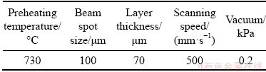
The TC4 plate with dimension of 38 mm �� 18 mm �� 3 mm was manufactured by ARCAM A2 SEBM machine with spherical TC4 powder, as shown in Fig. 1(a). The processes of SEBM [27] were described as follows. Firstly, geometrical data file was built with a 3D computer aided design (CAD), which was sliced into layers with a defined thickness. Following the sliced pattern, a focused, high power laser or electron beam scanned and melted the precursor powders, forming a molten pool. As the heating source moved away, the molten pool cooled down quickly and solidified to form a track bead. This process was repeated to successively build new layers until a final geometry was completed. The powder was purchased from ARCAM, Sweden, and had a size distribution of 45-106 ��m. The chemical composition of the powder is given in Table 1. The processing parameters are summarized in Table 2. Figure 1(b) shows the surface micro-morphology of the as-built TC4 samples, where processing gullies and a large number of unmelted or incompletely melted powders are observed on the surface. The surface roughness of the sample was measured to be Ra=33.45 ��m and Rz=166.23 ��m (according to ASME B46.1-2009).
Prior to the MAO treatment, as-built samples were ultrasonically cleaned in acetone for 20 min and dried in the air. The MAO-TC4 was prepared in Na2SiO3 system solution, and the electrolyte containing sodium metasilicate is one of the most commonly used electrolytes [28]. During MAO process, the SEBM-TC4 alloy samples acted as anode and stainless steel as the cathode. MAO oxide films were prepared at input voltages of 400, 420 and 450 V, respectively.

Fig. 1 Surface morphologies of as-built SEBM-TC4
Table 1 Chemical compositions of TC4 powder (wt.%)
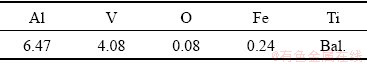
Table 2 Parameters used for TC4 manufacturing with Arcam A2 system
2.2 Characterizations of MAO coating
The surface and cross-section morphologies of MAO-TC4 alloy were observed by field emission scanning electron microscopy (FE SEM, JSM- 6700F, Japan). Prior to observation, samples were ground by 320, 500, 1200, 1500 and 2000 grit metallographic sandpaper gradually and then polished with 0.5 ��m diamond polishing agent. Element analysis of coatings was carried out by the energy dispersive X-ray spectroscopy (EDS, JSM-6700F, Japan) associated with the SEM system. The accelerating voltage is 15 kV, and the working distance is 15 mm. The phase compositions of the coatings were analyzed by X-ray diffraction (XRD-7000, Japan) using Cu K�� radiation.
The polarization curves were measured using an electrochemical workstation (PARSTAT 4000, America) with three standard electrodes: platinum auxiliary electrode, saturated calomel reference electrode (SCE) and working electrode at room temperature. Samples with and without MAO (with surface area exposure of 1 cm2) were immersed in 3.5% NaCl solution for 30 min to test the open circuit voltage, and then the scan rate was 2 mV/s to measure the polarization curves.
The wear experiment was conducted by using a ball-on-disk reciprocal tribometer (HT-1000). A Si3N4 ceramic ball with hardness of HV 2200 and diameter of 5 mm was employed as counterpart. The experimental load was 200 g, the friction track radius was set to be 3 mm, the motor speed was 50 r/min and the wear time was 30 min. The experiment was conducted at room temperature (25.6 ��C) and humidity of (70��1)%.
3 Results and discussion
3.1 Phase structure and coating morphology

Fig. 2 Contents of rutile and anatase phases in MAO coatings at different applied voltages (a) and XRD patterns of SEBM-TC4 with and without MAO (b) (A: Anatase; R: Rutile; ��: ��-Ti; ��: ��-Ti)
The XRD patterns of the SEBM-TC4 without and with micro-arc oxidation at different voltages are shown in Fig. 2(a), and the diffraction intensity of each peak is marked. The substrate contains �� and �� phases. Compared with the samples without MAO, new phases appear after MAO treatment, which are analyzed as titanium dioxide of rutile phase and anatase phase. After micro-arc oxidation, the diffraction peak intensities of ��-Ti and ��-Ti decrease significantly, and the diffraction peak of ��-Ti even tends to disappear. This is because the micro-arc oxidation coating on the surface of the sample covers the original matrix. ��-Ti phase is still present because MAO coating is thin and porous. Ti transforms into the Ti4+ ions at the high voltage and temperature in the arc discharge stage and Ti4+ ions subsequently react with other ions such as O2- or OH- in the discharge channels. TiO2 is formed by outward migration of Ti4+ ions from substrate metal to discharge channels and inward migration of O2-/OH- from electrolyte to discharge channels at high temperature. The main reactions in the electrolyte are as follows [28]:
Ti��Ti4++4e (1)
Ti4++H2O��TiO2+H+ (2)
With the applied voltage increasing, the diffraction peak intensities of both rutile and anatase TiO2 increase, which indicates that the Reaction (2) could only be fully carried out at a certain voltage. At the same time, both Ti and TiO2 phases have strong diffraction peak intensity at the voltage of 420 V, indicating that Reaction (2) reaches stability and is fully carried out. Previous studies [26,29,30] have shown that anatase phase is a metastable phase and changes to rutile phase at 800 ��C under arc discharge of micro-arc oxidation. The proportion of anatase phase of TiO2 is calculated according to the following equation [26]:
WR=1/(1+0.8IA/IR) (3)
where IA and IR are the diffraction peak intensities corresponding to anatase phase (101) and rutile phase (110), respectively.
The contents of anatase phase and rutile phase under different micro-arc oxidation voltages are shown in Fig. 2(a). With the increase of applied voltage, the content of rutile phase TiO2 gradually increases, while that of anatase phase TiO2 decreases. Due to the high temperature and high pressure generated at the membrane base interface during MAO reaction, the metastable anatase phase TiO2 gradually transforms into rutile phase TiO2. When anatase TiO2 is the main component, anatase will generate residual compressive stress to hinder crack growth and improve fatigue life [31].
CHEN et al [26] reported that the micro-arc oxidation process could be divided into five stages: anodic oxidation stage, passive film puncturing stage, rapid growth of micro-arc oxidation stage, large arc discharge stage and self-repairing stage. In the film puncturing stage, the voltage rises high enough to break through the oxidation film and a discharge channel forms. Meanwhile, discontinuous micro-arc oxidation film and volcanic porous ceramic layer are present, as shown in Fig. 3.
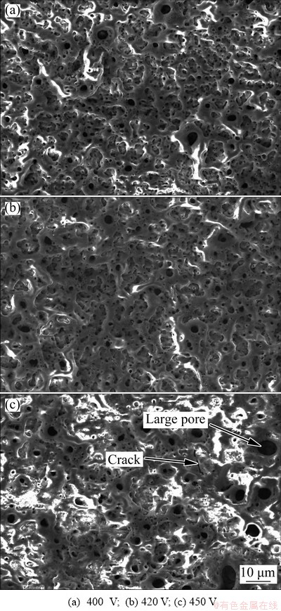
Fig. 3 Surface morphologies of SEBM-TC4 samples after MAO at different voltages

Fig. 4 Pore size distribution of surface topography on SEBM-TC4 samples after MAO at different voltages
Figure 3 presents the typical surface morphologies of MAO coating at different voltages on SEBM-TC4 substrate. It is seen that the surface is covered with different-size pores, and the sizes and shapes of pores change greatly with the applied voltage increasing. As shown in Fig. 4, the Image J software was used to calculate the pore size of the MAO coating surface and the pore size distribution was obtained. More than 95% of pores distribute between 0 and 0.5 ��m. It can also be seen that the pore size distribution under different voltages is uniform. This indicates that the uniform-size micropores form in the process of micro-arc oxidation. At 450 V, pores with size larger than 10 ��m appear (Fig. 3(c)). Moreover, there are no pores over 10 ��m at voltages of 400 and 420 V. This is because with the oxidation voltage increasing, small discharge channels are connected to each other to form larger discharge channels. In addition, during the formation of micro-arc oxidized ceramic layer, the high voltage generates a lot of heat, which makes the temperature of the reaction interface rise sharply. Thus, the quenching occurs under the action of rapid cooling of the electrolyte, leading to the generation of micro-cracks on the surface (Fig. 3(c)).
In order to measure the B-F interface bonding and coating thickness, the cross-sectional morphologies of the MAO coating under different voltages were observed. Figure 5 shows the cross-sectional morphologies of SEBM-TC4 after MAO treatment under applied voltage of 400, 420 and 450 V. It can be seen that the thickness of MAO coating increases with the applied voltage. At 400, 420 and 450 V, the coating thickness values are (1.12��0.37), (1.27��0.36) and (1.54��0.44) ��m, respectively. YAO et al [25] prepared MAO coating on SLM-TC4 surface, and the coating thickness was (1.09��0.14), (2.12��0.25), (3.14��0.64) and (5.34��0.95) ��m at 5, 10, 15 and 20 min of MAO, respectively. The interface between the substrate and MAO coating is relatively smooth, which is conducive to the combination of substrate and MAO coating. The rapid growth in micro-arc oxidation stage has a great contribution to the thickness of coating.
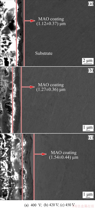
Fig. 5 Cross-sectional morphologies of SEBM-TC4 samples after MAO at different voltages
The molten oxides are sprayed outward through the discharge channel and cooled and solidified under the action of electrolyte on the surface of the sample. In the process of micro-arc oxidation, the ceramic layer is further oxidized, the original film is repeatedly broken down, and the thickness of the oxidation film increases. The breakdown of the film layer always occurs in the area where the oxidation film is relatively thin. After the breakdown, the molten oxide on the film layer is cooled and solidified under the action of electrolyte, and the film layer is thickened. The next breakdown occurs in the area where the film layer is relatively thin.
3.2 Electrochemical corrosion
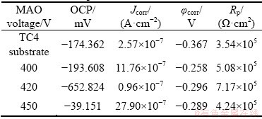
In order to investigate the corrosion resistance of the samples before and after MAO treatment, the electrochemical experiments were carried out. Figure 6 presents the polarization curves and Bode plots of the TC4 without MAO and treated by MAO at different oxidation voltages in 3.5% NaCl. The open circuit potential (OCP), corrosion current density (Jcorr), corrosion potential (��corr) and linear polarization resistances (Rp) are given in Table 3. It is shown that the MAO coating displays the higher ��corr. The higher the ��corr is, the lower the thermodynamic corrosion tendency is [32]. The Jcorr is an important parameter to determine the corrosion resistance of coating. The lower the corrosion current densities show, the better the corrosion resistance is, because of the restriction of the anodic reactions of the MAO coating [32]. According to the Fig. 6 and Table 3, the Jcorr at 420 V is almost an order of magnitude smaller than that of the TC4 substrate, two times smaller than that at the other two voltages and |Z| is the largest. This indicates that the MAO coating formed at 420 V has the best corrosion resistance. The thickness and density of the film are two important parameters affecting the corrosion resistance of the micro-arc oxidation film layer. Although the film thickness is the largest when the applied voltage is the highest, the micropores penetrate, at the same time, cracks are generated, and the etching solution passes through the film. When the voltage is below 420 V, the thickness of the film layer is moderate, the density of the porous surface coating is high, and the internal dense layer has the resistance to hydrogen carbide. Thus, the corrosion resistance of the film layer is the best at this voltage. However, the Jcorr of TC4 sample after being MAO-treated at 450 V is rather large than that of the substrate alloy, which is due to large pores and cracks appearing on the surface of MAO film at this voltage, as shown in Fig. 3(c). This leads to pitting or crevice corrosion on the surface and reduces the corrosion resistance. Studies [33] have shown that the influence of surface aperture size on corrosion resistance is greater than that of film thickness, and the large-diameter micropores can reduce the ability of the film to resist corrosive media, thereby reducing the corrosion resistance of the film. The other reason is that rutile and anatase TiO2 phases form, and a suitable proportion of rutile and anatase TiO2 phases is produced at 420 V. But, the applied voltage has a slightly effect on corrosion potential.

Fig. 6 Polarization curves (a) and experimental Bode plots (b) of TC4 substrate and MAO coatings at different voltages in 3.5% NaCl solution
Table 3 Electrochemical parameters calculated from electrochemical experiment
3.3 Wear resistance
Figure 7(a) shows the effects of wear time on coefficient of friction (COF) for the as-built TC4 substrate and MAO coatings at three different voltages. For TC4 substrate, the COF is about 0.2, and the curve is stable in the whole process of friction and wear. The COF of MAO coating increases sharply within 5 min of the wear process, and then levels off. With the MAO voltage increasing, the friction coefficient also increases. Then, the average COF is calculated and the wear loss of MAO coating and TC4 substrate in the wear process is measured. The results are shown in Fig. 7(b). It can be seen that as the micro-arc oxidation voltage increases, the COF and wear loss of different-thickness layers increases under the same friction condition. The COF and the wear loss of the sample with the micro-arc oxidation film layer are larger than those of the substrate because the outer layer of the micro-arc oxidation film has a porous structure. In the friction and wear process, the protrusion on the surface of the coating is firstly worn away, and the frictional force becomes large, leading to the high COF of the micro-arc oxidation coating. The compactness and phase composition of the film layer are also important factors affecting the wear resistance of the film layer. When the phase component contains oxides with high hardness, the membrane layer has high hardness and good wear resistance. However, when the membrane layer is less dense (for example, the large pores or cracks appear), it is possible to reduce the wear resistance of the membrane layer.
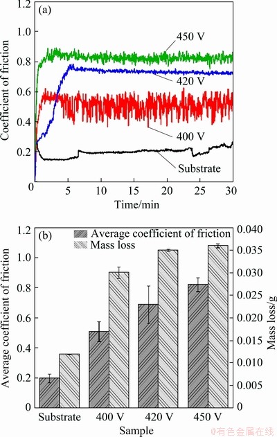
Fig. 7 Coefficient of friction (a), and mass loss and average coefficient of friction (b) of TC4 without and with MAO treatment at different voltages
Figure 8 displays the wear morphologies of the SEBM-TC4 substrate and the MAO coatings with different applied voltages, both at low and high magnification, as well as the EDS results of wear trace on MAO coatings. It can be clearly observed that a group of parallel grooves appear along the wear direction in Figs. 8(a, b), which represents typical abrasive wear characteristics. But the wear level of TC4 substrate is slightly less than that of MAO coating with applied voltage of 420 V, and the wear loss and friction coefficient are also minimal. At applied voltage of 400 V, the coating is thin, and is completely worn off during friction in short time. Therefore, the mass loss and friction coefficient of MAO coating at this voltage are higher than those of the substrate. The ceramic ball of Si3N4 is much harder than the TC4 substrate. During the sliding process, the Si3N4 ceramic ball causes the protrusions on the uneven surface to peel off, and produces some small hard debris particles. Then, the Si3N4 ceramic ball, hard debris particles and substrate materials lead to a three-body abrasive wear mode. The wear traces in Figs. 8(c, d) are narrower and the surfaces are less worn than those in Fig. 8(b). Shallow grooves and coating peeling can be observed, showing the characteristics of adhesive wear. And crack initiation tends to occur near coating peeling. Combined with the EDS results in Figs. 8(b2, c2, d2), it could be found that the coatings are worn away. With the repeated sliding of the Si3N4 ceramic ball on the surface of the sample, the crack gradually expands. When the critical value of crack growth is reached, delamination occurs, which eventually leads to fatigue wear. As for the MAO-treated sample at 400 V, the wear loss decreases and the friction coefficient increases compared with the MAO-treated samples at 420 and 450 V.
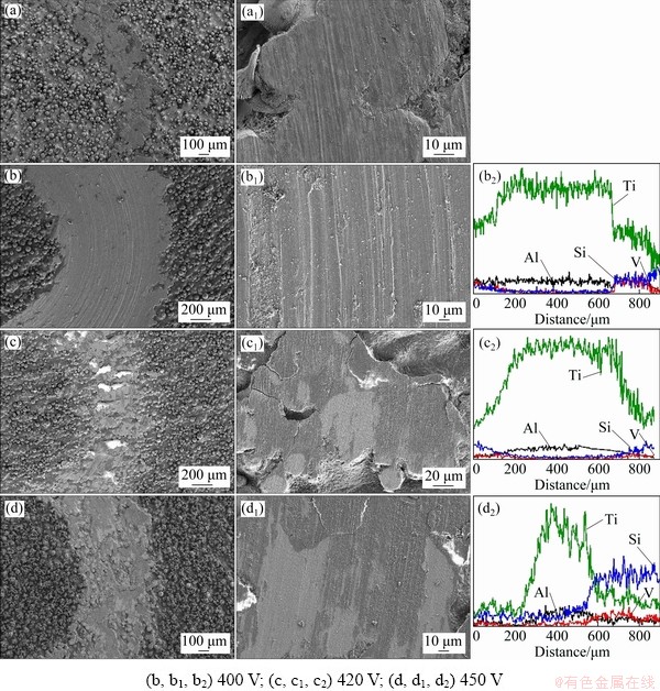
Fig. 8 Wear morphologies and EDS profiles of TC4 substrate (a, a1) and MAO-treated samples with different applied voltages

Fig. 9 2D/3D profiles of wear trace of MAO coatings with different applied voltages
As can be seen from Fig. 8, the wear resistance of MAO coatings is not as good as that of TC4 substrate. On one hand, the hardness of MAO coating is lower than that of matrix; on the other hand, the surface layer of MAO coating is porous and loose, which makes the wear resistance of MAO-treated samples worse. At the same time, according to the 2D and 3D morphologies of the wear trace in Fig. 9, the wear trace of MAO-treated sample at 400 V is deeper than that at other voltages. The friction coefficient of MAO-treated samples under applied voltage of 400 V is the lowest, which is related to the appropriate proportion between rutile and anatase TiO2. It can be concluded that the proportion between rutile phase and anatase TiO2 is crucial for the comprehensive performance of MAO-treated TC4 alloys.
4 Conclusions
(1) MAO films are fabricated successfully on SEBM-TC4. The surface morphology is porous with uniform size distribution, and pores over 10 ��m appear on MAO-treated samples with applied voltage of 450 V. At applied voltage of 400, 420 and 450 V, coating thicknesses are (1.12��0.37), (1.27��0.36) and (1.54��0.44) ��m, respectively.
(2) The XRD analysis of the coating shows that the MAO coatings mainly consist of rutile and anatase TiO2.
(3) MAO coating prepared at 420 V has the lowest corrosion current density and the largest |Z|, which indicates the best corrosion resistance. MAO treatment could deteriorate the wear properties of the SEBM-TC4 alloy.
References
[1] NICOLETTO G, MAISANO S, ANTOLOTTI M, DALL��AGLIO F. Influence of post fabrication heat treatments on the fatigue behavior of Ti-6Al-4V produced by selective laser melting [J]. Procedia Structural Integrity, 2017, 7: 133-140.
[2] LI Han-song, GAO Chuan-ping, WANG Guo-qian, QU Ning-song, ZHU Di. A study of electrochemical machining of Ti-6Al-4V in NaNO3 solution [J]. Scientific Reports, 2016, 6(1): 35013.
[3] XU Zhen-zhen, DONG Zhi-qiang, YU Zhao-Hui, WANG Wen-ke, ZHANG Jian-xun. Relationships between microhardness, microstructure, and grain orientation in laser-welded joints with different welding speeds for Ti6Al4V titanium alloy [J]. Transactions of Nonferrous Metals Society of China, 2020, 30: 1277-1289.
[4] GUO Kuai-kuai, LIU Chang-sheng, CHEN Sui-yuan, DONG Huan-huan, WANG Si-yu. High pressure EIGA preparation and 3D printing capability of Ti-6Al-4V powder [J]. Transactions of Nonferrous Metals Society of China, 2020, 30: 147-159.
[5] LEON A, LEVY G K, RON T, SHIRIZLY A, AGHION E, The effect of strain rate on stress corrosion performance of Ti6Al4V alloy produced by additive manufacturing process [J]. Journal of Materials Research and Technology, 2020, 9: 4097-4105.
[6] ZHU Yan-yan, CHEN Bo, TANG Hai-bo, CHENG Xu, WANG Hua-ming, LI Jia. Influence of heat treatments on microstructure and mechanical properties of laser additive manufacturing Ti-5Al-2Sn-2Zr-4Mo-4Cr titanium alloy [J]. Transactions of Nonferrous Metals Society of China, 2018, 28: 36-46.
[7] LI Jia-fang, HE Xiao-jing, ZHANG Guan-nan, HANG Rui-qiang, HUANG Xiao-bo, TANG Bin, ZHANG Xiang-yu. Electrochemical corrosion, wear and cell behavior of ZrO2/TiO2 alloyed layer on Ti-6Al-4V [J]. Bioelectro- chemistry, 2018, 121: 105-114.
[8] MA Qian, XU Wei, BRANDT M, TANG Hui-ping. Additive manufacturing and post processing of Ti-6Al-4V for superior mechanical properties [J]. MRS Bulletin, 2016, 41: 775-784.
[9] ZHANG Du-yao, QIU Dong, GIBSON M A, ZHENG Yu-feng, FRASER H L, STJOHN D H, EASTON M A. Additive manufacturing of ultrafine-grained high-strength titanium alloys [J]. Nature, 2019, 576: 91-95.
[10] FRAZIER, WILLIAM E. Metal additive manufacturing: A review [J]. Journal of Materials Engineering and Performance, 2014, 23: 1917-1928.
[11] KORNER C. Additive manufacturing of metallic components by selective electron beam melting��A review [J]. International Materials Reviews, 2016, 61(5): 361-377.
[12] GONG Xiao-juan, CUI Yu-jie, WEI Dai-xiu, LIU Bin, LIU Rui-ping, NIE Yan, LI Yun-ping. Building direction dependence of corrosion resistance property of Ti-6Al-4V alloy fabricated by electron beam melting [J]. Corrosion Science, 2017, 127: 101-109.
[13] WANG Ji, TANG Hui. Review on metals additively manufactured by SEBM [J]. Materials Technology, 2015, 31: 86-89.
[14] MURR L E, ESQUIVEL E V, QUINONES S A, GAYTANA S M, LOPEZA M I, MARTINEZA E Y, MEDINAC F, HERNANDEZA D H, MARTINEZA E, MARTINEZA J L, STAFFORDA S W, BROWNA D K, HOPPED T, MEYERSD W, LINDHEE U, WICKERC R B. Microstructures and mechanical properties of electron beam-rapid manufactured Ti-6Al-4V biomedical prototypes compared to wrought Ti-6Al-4V [J]. Materials Characterization, 2009, 60: 96-105.
[15] HARRYSSON O L A, CANSIZOGLU O, MARCELLIN- LITTLE D J, CORMIER D R, WEST H A. Direct metal fabrication of titanium implants with tailored materials and mechanical properties using electron beam melting technology [J]. Materials Science & Engineering: C (Materials for Biological Applications), 2008, 28: 366-373.
[16] MURR L E, GAYTAN S M, MEDINA F, MARTINEZ E, MARTINEZ J L, HERNANDEZ D H, MACHADO B I, RAMIREZ D A, WICKER R B. Characterization of Ti-6Al-4V open cellular foams fabricated by additive manufacturing using electron beam melting [J]. Materials Science & Engineering: A (Structural Materials: Properties, Microstructure and Processing), 2010, 527: 1861-1868.
[17] ROTELLA G, IMBROGNO S, CANDAMANO S, UMBRELLO D. Surface Integrity of machined additively manufactured Ti alloys [J]. Journal of Materials Processing Technology, 2018, 259: 180-185.
[18] NICOLETTO G, KONECNA R, FRKAN M, RIVA E. Surface roughness and directional fatigue behavior of as-built EBM and DMLS Ti6Al4V [J]. International Journal of Fatigue, 2018, 116: 140-148.
[19] VAYSSETTE B, NICOLAS S, BRUGGER C, ELMAY M, PESSARD E. Surface roughness of Ti-6Al-4V parts obtained by SLM and EBM: Effect on the high cycle fatigue life [J]. Procedia Engineering, 2018, 213: 89-97.
[20] FELICE R, FABIO S, STEFANIA F, ANTONINO S, ANTONELLO A, PIERPAOLO C. Microstructure and surface analysis of friction stir processed Ti-6Al-4V plates manufactured by electron beam melting [J]. Journal of Manufacturing Processes, 2019, 37: 392-401.
[21] JIANG Xu-dong, WANG Yong-qian, PAN Chun-xu. Micro-arc oxidation of TC4 substrates to fabricate TiO2/YAG: Ce3+ compound films with enhanced photocatalytic activity [J]. Journal of Alloys & Compounds, 2011, 509: 137-141.
[22] WANG Ya-ming, JIANG Bai-ling, LEI Ting-quan, JIA De-chang, ZHOU Yu. Research progress of wear resistant coating on Ti6Al4V alloy surface [J]. Journal of Materials Engineering, 2016, 3: 38-43.
[23] KOSHURO V, FOMIN A, RODIONOV I. Composition, structure and mechanical properties of metal oxide coatings produced on titanium using plasma spraying and modified by micro-arc oxidation [J]. Ceramics International, 2018, 44: 12593-12599.
[24] CHENG Fang, LI Sha-sha, GUI Wan-yuan, LIN Jun-ping. Surface modification of Ti-45Al-8.5Nb alloys by microarc oxidation to improve high-temperature oxidation resistance [J]. Progress in Natural Science: Materials International, 2018, 28: 132-136.
[25] YAO Jian-hua, WANG Ye, WU Guo-long, SUN Min, WANG Miao, ZHANG Qun-li. Growth characteristics and properties of micro-arc oxidation coating on SLM-produced TC4 alloy for biomedical applications [J]. Applied Surface Science, 2019, 479: 727-737.
[26] CHEN Wei-wei, WANG Ze-xin, SUN Lei, LU Sheng. Research of growth mechanism of ceramic coatings fabricated by micro-arc oxidation on magnesium alloys at high current mode [J]. Journal of Magnesium and Alloys, 2015, 3: 253-257.
[27] LIU Shun-yu, SHIN Y C. Additive manufacturing of Ti6Al4V alloy: A review [J]. Materials & Design, 2019, 164: 107552.
[28] STOJADINOVIC S, VASILIC R, PETKOVIC M, BELCA I, ZEKIC A, ZEKOVIC L. Characterization of the plasma electrolytic oxidation of titanium in sodium metasilicate [J]. Applied Surface Science, 2013, 265: 226-233.
[29] XIE Rui-zhen, LIN Nai-ming, ZHOU Peng, ZOU Jiao-juan, HAN Peng-ju, WANG Zhi-hua, TANG Bin. Surface damage mitigation of TC4 alloy via micro arc oxidation for oil and gas exploitation application: Characterizations of microstructure and evaluations on surface performance [J]. Applied Surface Science, 2018,436: 467-476.
[30] YEROKHIN E, PARFENOV E V, MATTHEWS A. In situ impedance spectroscopy of the plasma electrolytic oxidation process for deposition of Ca- and P-containing coatings on Ti [J]. Surface and Coatings Technology, 2016, 301: 54-62.
[31] QIAN Chao-shi, LI Peng-fei, LIU Liang, GUO Feng, YA Ya. Study on morphologies and structures of ceramic coating prepared by micro-arc oxidation on TC4 alloy [J]. Advanced Materials Research, 2011, 189-193: 395-399.
[32] FAZEL M, SHAMANIAN M, SALIMIJAZI H R. Enhanced corrosion and tribocorrosion behavior of Ti6Al4V alloy by auto�Csealed micro-arc oxidation layers [J]. Biotribology, 2020, 23: 100131.
[33] LUO Jun-ming, WU Xiao-hong, XU Ji-lin. The influence of electrolyte components on the corrosion resistance and wear resistance of TiCP/Ti6Al4V composite micro-arc oxide film [J]. Journal of Inorganic Materials, 2017, 32: 418-424.
�� ��1��������1�����ľ�1���� ��2�������1��������2������Ƽ3
1. ����������ѧ ���Ͽ�ѧ�빤��ѧԺ������ 710048��
2. ���������Ƽ���ѧ ұ���빤��ѧԺ������ 710055��
3. ������ɫ�����о�Ժ ��������Ϲ����ص�ʵ���ң����� 710016
ժ Ҫ��Ϊ�˷�����������ѹ��Ti6Al4V(TC4)�Ͻ�ʴ��ĥ�����ܵ�Ӱ�죬�ֱ���400��420��450 V�Ե�����ѡ���ۻ�(SEBM)�Ʊ���TC4��Ʒ�������������洦���������������������ʱ����¶ȵ����ӣ�����̬ ���ѿ���TiO2��ת��Ϊ���ʯ��TiO2��MAOĤ������ò��Ҫ�dzߴ�ֲ����ȵĴ����ף�����450 V��ѹ �³������ƺ� >10 ��m�Ŀ�϶��MAOĤ�����ʩ�ӵ�ѹ������ء�MAOĤ����ʴ���ܺ�ĥ������������� �֡������׳ߴ�ֲ���Ĥ���йأ���MAO��ѹΪ420 Vʱ����ʴ�����ܶ���С(0.960��10-7 A/cm2)���迹���(7.17��105 ����cm2���� ��ʴ������ã���ͬ�غ������£�Ϳ���Ħ��������ĥ���������ڻ���ģ�����MAO ʩ�ӵ�ѹ�����ӣ�MAOĤ��ĥ�������ĥ��ĥ��ת��Ϊճ��ĥ����450 V��ѹʱճ��ĥ��Ӿ磬Ħ������Ҳ���Ϊ0.821��
�ؼ��ʣ�������ѡ���ۻ�����������TC4�Ͻ𣻸�ʴ��ĥ������
(Edited by Bing YANG)
Foundation item: Projects (51504191, 51671152, 51874225) supported by the National Natural Science Foundation of China; Project supported by the Fund of State Key Laboratory of Porous Metal Materials, China
Corresponding author: Shi-feng LIU; Tel: +86-29-82202933; E-mail: liushifeng66@126.com
DOI: 10.1016/S1003-6326(20)65366-3

