J. Cent. South Univ. Technol. (2010) 17: 560-565
DOI: 10.1007/s11771-010-0523-3 
Modeling of electrode system for three-phase electric arc furnace
WANG Yan(王琰)1, 2, MAO Zhi-zhong(毛志忠)1, TIAN Hui-xin(田惠欣)1, LI Yan(李妍)1, YUAN Ping(袁平)1
1. School of Information Science and Engineering, Northeastern University, Shenyang 110004, China;
2. Liaoyang Municipal Development and Reform Commission, Liaoyang 111000, China
? Central South University Press and Springer-Verlag Berlin Heidelberg 2010
Abstract: To simulate the process of electrode operation, a dynamic model describing the electrode system of three-phase electric arc furnace was developed. This new model can be divided into three submodels in terms of the practical situation. They are the power supply system model the electric arc model and the hydraulic actuator system model. According to the basic circuit theory, the power supply system model where the high voltage transmission circuit and mutual inductances were considered, was set up. The electric arc model, which was novel for the electrode control, served as the electrical load and was connected to the power supply system model. The hydraulic actuator system model consists of the proportional valve part that is modeled to capture the dead-zone nonlinear characteristics and the hydraulic cylinder part where the impact of the load force is taken into account. By comparing simulation data and actual data, the results show that the electrode system model is proved to be accurate.
Key words: electric arc furnace; electrode system model; electric arc model; simulation
1 Introduction
Nowadays, electric arc furnaces are commonly used in metallurgical industry to convert scrap into steel with three-phase electric power as the main energy source [1-2]. In the electric arc furnace operation, an electrode system plays an important role and can be directly related to the power level input into the electric arc furnace by adjusting the furnace transformer tap and arc length. Therefore, the construction of a complete dynamic electrode system model is essential to understand the electrode operating process and helps to achieve advanced control techniques. However, developing a dynamic model has so far been quite a challenging task due to the nonlinearity and complexity of electrode system.
Literature, relating to the modeling of electrode system, is limited to date. In the limited literature, most of the existing models were developed using the techniques of system identification [3-5] and neural network [6-7]. Those mentioned models are regarded as black box models that descriptions about the internal states are limited and those models are mostly single- phase models. They, more importantly, may not give a more complete realistic description regarding the physical parts of electrode system in this way. In other models, the power supply system was presented based on equivalent circuit descriptions and the electric arc resistance could be considered as a static linear relation with respect to its length [8-9]. However, these descriptions in a direct current state are too simple and all connections to the primary side of furnace transformer are also neglected. In addition, the key nonlinear characteristic of electric arc cannot be reflected in the above static linear relation.
In this work, a new dynamic electrode system model for a three-phase electric arc furnace was proposed. In this model, a new electric arc model was utilized, which is actually a nonlinear differential equation of arc conductance, arc current and arc length. Meantime, the high voltage transmission circuit feeding the arc furnace transformer, tap changer on the furnace transformer and mutual inductances between the three phases and the dead-zone nonlinear characteristics in the hydraulic actuator system were taken into account. The simulation results verified the effectiveness of this new dynamic electrode system model.
2 Electrode system model
According to actual components, the overall electrode system can typically be divided into three main subsystems. Those are the power supply system, the electric arc and the hydraulic actuator system. A schematic diagram of electrode system is illustrated in Fig.1. The mathematical model of each subsystem will be discussed in the following sections.
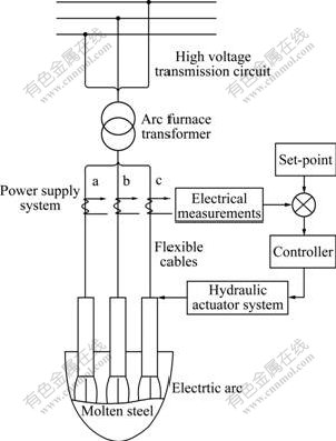
Fig.1 Schematic diagram of electrode system
2.1 Power supply system
The power supply system is the source of electrical energy to the electric arc furnace and is composed of the high voltage transmission circuit, the arc furnace transformer and the flexible cables. Here, detailed descriptions on the power supply system are presented in order to add power quality aspects such as harmonic analysis to the model because the electric arc furnace can cause large power quality problems on the electrical network [10]. Meantime, this will also improve the accuracy of simulation results.
For the purpose of simplification, the following three assumptions are made.
(1) All the circuit parameters in the arc furnace transformer are equivalent to system resistance rs and system inductance Ls.
(2) Furnace transformer is considered as an ideal transformer with ratio tp, and the phase shift is neglected [11].
(3) The mutual inductances have the same effect among the phases because the equilateral triangle configuration of flexible cables is used in the modern electric arc furnace.
With the above assumptions, the power supply system can be equivalent to a three-phase circuit as shown in Fig.2.
In Fig.2, Ua, Ub and Uc are symmetry voltage sources and can be expressed by
 (1)
(1)
where U is the peak value of source balanced voltage; f is the frequency of electrical system; and t is time.
According to Fig.2, the following set of equations can be formed:
 (2)
(2)
where tp is the arc furnace transformer tap ratio; rt and Lt are the resistance and inductance in the arc furnace transformer; Ij (j=a, b, c) is the instantaneous electrode current in each phase; rj (j=a, b, c) and Lj (j=a, b, c) are the resistance and inductance of flexible cables in each phase; gj (j=a, b, c) is the instantaneous arc conductance in each phase; and  (j, j1=a, b, c and j≠j1) is mutual inductance in phase j.
Applying Kirchoff’s current law, the following equation can be obtained:
Ia+Ib+Ic=0 (3)
Together, the power supply system model is proposed by integrating the results of Eqs.(1)-(3).
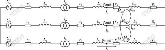
Fig.2 Three-phase equivalent circuit diagram of power supply system
2.2 Electric arc system
The arc power depends on the arc length under the constant furnace transformer tap, which is adjusted by means of the electrode system. As a result, the basic description of an arc model for the electrode system depends on arc length item. A new dynamic electric arc model proposed by WANG et al [12] was used in this work.
Based on the fundamental principle of energy conservation, the power equation for the electric arc can be presented by
 (4)
(4)
where E is the thermal energy which is stored into the electric arc; P is the total power delivered to the arc; and P0 is the power transmitted in the form of heat to the external environment.
The power-input P is given as:
 (5)
(5)
where I is the instantaneous electrode current; and g is the instantaneous arc conductance.
The power-loss P0 is described as
 (6)
(6)
where k1 and β are parameters; and L is the arc length.
Energy E stored into the electric arc and the instantaneous arc conductance g can be described as
 (7)
(7)
 (8)
(8)
where p is the atmosphere gas pressure; Ta is the temperature of the electric arc column; T0 is the ambient temperature; r is the arc radius; σ is the instantaneous arc conductance per unit volume; σ0 is a constant and α is a characteristic temperature for ionization of the gas, α= 1.601 4×10⁴ K (for air at 1.013×10⁵ Pa) [13].
Based on the above equations, the differential equation of the arc model can be given as
 (9)
(9)
where
 (10)
(10)
 (11)
(11)
In short, the major difference between the proposed arc model and existing models is that this new dynamic arc model can be used for the electrode system. Parameters k1 and λ in Eq.(9) relate to the arc furnace transformer tap and the arc furnace process.
2.3 Hydraulic actuator system
Components in a hydraulic actuator system, for the aim of this work, are the proportional valve and the hydraulic cylinder. The proportional valve could be simply expressed as the proportional component [14]. In reality, however, dead-zone characteristic is common in almost real hydraulic actuator system. Also, it is little rational that no saturation limits are placed on the controller output. In order to better reflect real-life characteristics, the proportional valve opening is described by
 (12)
(12)
where x is the proportional valve opening;  is the input current of proportional valve; d=[dl, dr] is the dead-zone width of valve; Ksvl and Ksvr are the proportional valve gains; xmin is the negative maximum valve opening; xmax is the positive maximum valve opening; and =[Il, Ir] is the input current range of proportional valve.
Input current is calculated in the following equation:
 (13)
(13)
where ka is the proportional coefficient and u is the output of controller (the input of hydraulic actuator system).
The flow for proportional valve can be expressed as [15]:
Q=Kqx-KcpL (14)
where Q is the flow; Kq is the flow gain; Kc is the pressure flow coefficient; and pL is the load pressure.
For a hydraulic cylinder, the flow continuity equations can be obtained as [16]:
 (15)
(15)
where Ap is the effective area on the piston; y is the displacement of piston; Ve is the volume of cylinder chambers; βe is the oil bulk modulus; and Ct is the leakage flow coefficient.
It is assumed that the mass of oil in the hydraulic cylinder is negligible and the load is rigid. Then, according to the Newton’s second law, the force equilibrium equation of hydraulic cylinder can be given as [16]:
 (16)
(16)
where m is the load mass connected to the piston; and F is the load force.
Eqs.(12)-(16) can be used to describe the hydraulic actuator system.
2.4 Interaction among submodels
The complete electrode system model mainly consists of an electrical section where the electric arc model serves as the three-phase load and is connected in a star configuration to a power supply system model and three hydraulic actuator systems. Each of the electrical phases is separately connected in series with a hydraulic actuator system model, for the main objective of changing the arc length. Note that the displacements of piston are assumed to be equal to the arc length with the assumption that electric arcs are present at all times.
L=y (17)
Disturbances on the length of electric arcs are added externally. Generally speaking, the interaction among the above three submodels constitutes the proposed electrode system model. Fig.3 shows the analysis scheme of integrated model, where u denotes the input to the hydraulic actuator system model and the output voltage and current for the electrical section are denoted by V1,RMS(t) and IRMS(t), respectively. V1,RMS(t) is the root mean square (RMS) value of voltage at point 1 as shown in Fig.2. IRMS(t) is the RMS value of electrode current. They are obtained separately in the following expressions:
 (18)
(18)
 (19)
(19)
where T is a cycle and U1(t) is the instantaneous value of voltage at point 1.
3 Model verification
In this section, the presented models will be validated based on the real electrode system for a 40 t electric arc furnace. The electrical section and complete electrode system model are simulated separately to illustrate the respective responses.
3.1 Transient properties of electric arc
To show the transient electrical properties of electric arc, the simulation of electrical section that is composed of a power supply system and a three-phase load represented by the highly nonlinear electric arcs is performed for the constant arc lengths. The constant arc length can represent typical characteristics of flat bath. The rated power of three-phase alternating current (AC) arc furnace transformer is 22 MW, and the tap setting line voltage are from 420 V to 35 kV. The simulation parameter values of power supply system model are shown in Table 1.
In the electric arc model, the parameters for all three phases are given in Table 2. The three interesting variables regarding the electrical behaviour of electric arc are arc voltage, arc current and arc current-voltage characteristic. These variables of phase a, simulated with the derived electrical section for 0.06 s, are illustrated in Fig.4. The simulation time is chosen as 0.06 s mainly because of using of 50 Hz operating frequency. The simulation results show only single phase properties because the curves for all three phases are more or less the same when constant arc length is applied to all three inputs.
The electric arc vanishes every time when the current crosses zero. To ignite the electric arc, as shown in Fig.4(a), the arc voltage must be increased to a necessary value. The value is necessary to establish an electric arc and is higher than its steady state value. The higher value of the arc voltage is visible at the beginning of every half cycle and also has an effect on the waveforms for arc current. This effect is visible in Fig.4(b). During the establishment of electric arc, arc current remains almost zero. The current-voltage characteristic is commonly used to illustrate the nonlinear behavior of electric arc. Such a characteristic is plotted in Fig.4(c). The simulation results agree well with the theory of electric arc. To validate the electrical section model more accurately, comparisons are performed between the data calculated by the proposed model and the actual data measured using Fluke435 power quality analyzer during the refine stage. From Fig.4, it can be seen that the waveforms of simulation data and the actual data are very similar. Hence, these results indicate that the proposed electrical section model is accurate.
3.2 Complete electrode system model
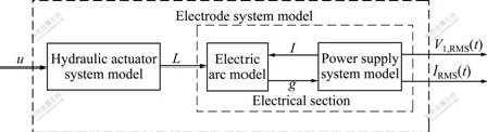
Fig.3 Analysis scheme of electrode system model
Table 1 Simulation parameters of power supply system model
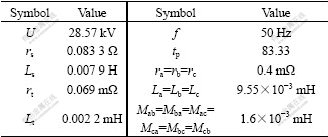
Table 2 Simulation parameters of electric arc model
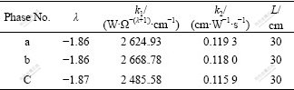
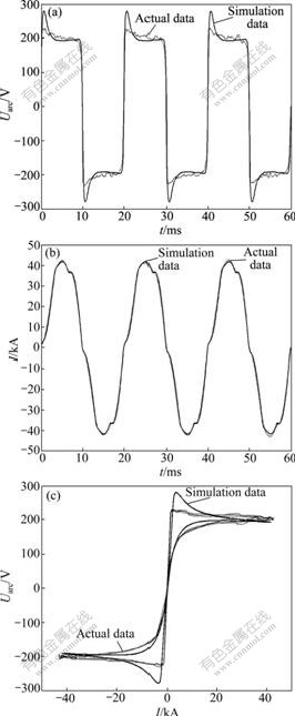
Fig.4 Comparisons between simulation data and actual data of phase a: (a) Arc voltage; (b) Arc current; (c) Arc current- voltage characteristic
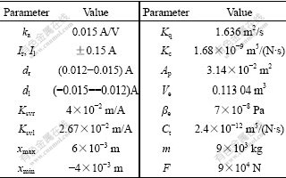
This section illustrates the complete electrode system model where three hydraulic actuator system models are connected to each of the three phases. For the electrode system model, the overall inputs are the actual outputs of controller as shown in Fig.5 and the outputs are V1,RMS(t) and IRMS(t) as described in Fig.6. The results on all three phases look similar and the results of only one phase are illustrated here. Note that the displacement of piston is multiplied by 100 to convert the output to centimeters, which is needed for the electrical section input. The parameter values of three hydraulic actuator system models are identical and presented in Table 3. From Fig.6, it can be seen that the simulation responses can basically correlate with the actual results except for the difference which is caused by the disturbances on the electric arc length. Hence, it is good enough for testing the performance of the derived electrode system model.
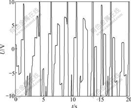
Fig.5 Curve of actual output voltage for controller of phase a
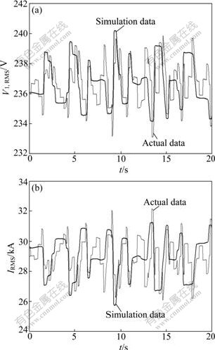
Fig.6 Comparisons between voltage/current simulated and that measured of phase a: (a) Effective value of voltage; (b) Effective value of current
Table 3 Simulation parameters of hydraulic actuator system model
4 Conclusions
(1) A new dynamic electrode system model for a three-phase electric arc furnace is developed according to the real-life configurations, which is composed of the power supply system, the electric arc and the hydraulic actuator system.
(2) Based on the comparisons between simulation data and measured data taken from a steel-making plant, this new electrode system model is proved to be accurate. The development of an electrode system model can not only be applied to facilitating the simulation of electrode operation, but also helping to achieve an advanced control system design with a reduced engineering labor cost compared with the traditional trial design procedure in this way.
References
[1] WEI D H, CRAIG I K, BAUER M. Multivariate economic performance assessment of an MPC controlled electric arc furnace [J]. ISA Transactions, 2007, 46(3): 429-436.
[2] OOSTHUIZEN D J, CRAIQ I K, PISTORIUS P C. Economic evaluation and design of an electric arc furnace controller based on economic objectives [J]. Control Engineering Practice, 2004, 12(3): 253-265.
[3] HAUKSDOTTIR A S, SODERSTROM T, THORFINNSSON Y P, GESTSSON A. System identification of a three-phase submerged arc ferrosilicon furnace [J]. IEEE Transactions on Control System Technology, 1995, 3(4): 377-387.
[4] LANG Zi-qiang, GU Xing-yuan, BAO Yu-an. Modeling and identification of electrode position controller in electric arc furnace [C]// International Conference on Control. London: IEE, 1991: 434-439.
[5] BILLINGS S A, BOLAND F M, NICHOLSON H. Electric arc furnace modeling and control [J]. Automatica, 1979, 15(2): 137-148.
[6] JANABI-SHARIFI F, JORJANI G, HASSANZADEH I. Using adaptive neuro fuzzy inference system in developing an electrical arc furnace simulator [C]// Proceedings of the 2005 IEEE/ASME International Conference on Advanced Intelligent Mechatronics. Piscataway: IEEE, 2005: 1210-1215.
[7] KING P E, NYMAN M D. Modeling and control of an electric arc furnace using a feedforward artificial neural network [J]. Journal of Applied Physics, 1996, 80(3): 1872-1877.
[8] BOULET B, LALLI G, AJERSCH M. Modeling and control of an electric arc furnace [C]// Proceedings of the American Control Conference. Piscataway: IEEE, 2003: 3060-3064.
[9] BALAN R, MATIES V, HANCU O, STAN S, CIPRIAN L. Modeling and control of an electric arc furnace [C]// 2007 Mediterranean Conference on Control and Automation. Piscataway: IEEE, 2007: 1077-1082.
[10] ALONSO M A P, DONSION M P. An improved time domain arc furnace model for harmonic analysis [J]. IEEE Transactions on Power Delivery, 2004, 19(1): 367-373.
[11] ZHENG T X, MAKRAM E B. An adaptive arc furnace model [J]. IEEE Transactions on Power Delivery, 2000, 15(3): 931-939.
[12] WANG Yan, MAO Zhi-zhong, LI Yan, TIAN Hui-xin, FENG Li-feng. Modeling and parameter identification of an electric arc for the arc furnace [C]// Proceedings of IEEE International Conference on Automation and Logistics. Piscataway: IEEE, 2008: 740-743.
[13] WANG Feng-hua. Study of modeling the electric arc furnace and its application [D]. Shanghai: Shanghai Jiao Tong University, 2006. (in Chinese)
[14] HE Qing-hua, HAO Peng, ZHANG Da-qing. Modeling and parameter estimation for hydraulic system of excavator’s arm [J]. Journal of Central South University of Technology, 2008, 15(3): 382-386.
[15] WU Le-bin, WANG Xuan-yin, LI Qiang. Fuzzy-immune PID control of a 6-DOF parallel platform for docking simulation [J]. Journal of Zhejiang University, 2008, 42(3): 387-391. (in Chinese)
[16] ZHANG You-wang, GUI Wei-hua. Compensation for secondary uncertainty in electro-hydraulic servo system by gain adaptive sliding mode variable structure control [J]. Journal of Central South University of Technology, 2008, 15(2): 256-263
Foundation item: Projects(2007AA04Z194, 2007AA041401) supported by the National High-Tech Research and Development Program of China
Received date: 2009-05-21; Accepted date: 2009-08-31
Corresponding author: WANG Yan, PhD; Tel: +86-24-83677007; E-mail: neu_wy100@yahoo.com.cn
(Edited by LIU Hua-sen)

