锰添加和精炼工艺对废镁制备的Mg-Mn合金除铁的影响
来源期刊:中国有色金属学报(英文版)2020年第11期
论文作者:古东懂 王佳文 陈俞宾 彭建
文章页码:2941 - 2951
关键词:除铁;熔体精炼处理;废镁;富铁颗粒;腐蚀敏感性
Key words:Fe reduction; melt refining process; magnesium scrap; Fe-rich particle; corrosion susceptibility
摘 要:研究由废镁加锰精炼制备的Mg-Mn合金的除铁、组织演变和腐蚀敏感性。结果表明,即使没有添加锰,近固熔(NSMT)处理也会引起显著的铁含量变化,这归因于熔体中铁的过饱和度较高。此外,在NSMT过程中,即使添加少量锰也会导致锰原子剧烈沉降。NSMT工艺可以提高富铁颗粒的生长速率,加速其沉降运动。然而,锰的加入会阻碍富铁颗粒的粗化过程。合金的腐蚀敏感性主要取决于铁的溶解度,而铁的溶解度可通过添加锰大大降低。而且,更多富铁颗粒的存在不一定会增加合金的腐蚀敏感性。因此,在由废镁制备的Mg-Mn合金的精炼过程中,基于NSMT工艺并添加合适的锰(约0.5%,质量分数)可以提高熔体的纯度,从而获得具有优异耐腐蚀性的合金。
Abstract: The Fe reduction, microstructure evolution and corrosion susceptibility of Mg-Mn alloys made from magnesium scrap refining with Mn addition were investigated. The results show that significant Fe content change occurs during near-solid-melt treatment (NSMT) process even in the absence of Mn, because of the high saturation of Fe in the melt. Furthermore, in the NSMT process, even a small amount of Mn addition can lead to a sharp deposition of Mn atoms. The NSMT process can increase the growth rate of the Fe-rich particles, and then accelerate their sinking movement. Nevertheless, the addition of Mn hinders the coarsening process of Fe-rich particles. Besides, the corrosion susceptibility of the alloys is mainly affected by the solubility of Fe, which can be significantly reduced by Mn addition. Moreover, the presence of more Fe-rich particles does not necessarily increase the corrosion susceptibility of the alloy. Consequently, in the refining process of Mg-Mn alloys made from magnesium scrap, on the basis of NSMT process and adding an appropriate Mn content (about 0.5 wt.%), the purity of the melt can be improved, thereby obtaining an alloy with excellent corrosion resistance.
Trans. Nonferrous Met. Soc. China 30(2020) 2941-2951
Dong-dong GU1, Jia-wen WANG1, Yu-bin CHEN1, Jian PENG1,2
1. State Key Laboratory of Mechanical Transmissions, College of Materials Science and Engineering, Chongqing University, Chongqing 400044, China;
2. Chongqing Research Center for Advanced Materials, Chongqing Academy of Science and Technology,
Chongqing 401123, China
Received 14 January 2020; accepted 24 June 2020
Abstract: The Fe reduction, microstructure evolution and corrosion susceptibility of Mg-Mn alloys made from magnesium scrap refining with Mn addition were investigated. The results show that significant Fe content change occurs during near-solid-melt treatment (NSMT) process even in the absence of Mn, because of the high saturation of Fe in the melt. Furthermore, in the NSMT process, even a small amount of Mn addition can lead to a sharp deposition of Mn atoms. The NSMT process can increase the growth rate of the Fe-rich particles, and then accelerate their sinking movement. Nevertheless, the addition of Mn hinders the coarsening process of Fe-rich particles. Besides, the corrosion susceptibility of the alloys is mainly affected by the solubility of Fe, which can be significantly reduced by Mn addition. Moreover, the presence of more Fe-rich particles does not necessarily increase the corrosion susceptibility of the alloy. Consequently, in the refining process of Mg-Mn alloys made from magnesium scrap, on the basis of NSMT process and adding an appropriate Mn content (about 0.5 wt.%), the purity of the melt can be improved, thereby obtaining an alloy with excellent corrosion resistance.
Key words: Fe reduction; melt refining process; magnesium scrap; Fe-rich particle; corrosion susceptibility
1 Introduction
It is generally known that magnesium and its alloys have many excellent properties, such as high specific strength, excellent castability and good biocompatibility, thus attracting more attention and enjoying a growing reputation when applied in many fields [1-3]. However, the potential advantages of magnesium alloys are severely restricted by their metallurgical quality, especially the purity of the alloys. Fe, as a conventional impurity element, exists in almost every stage of the manufacturing process, which should be controlled at a low level. Only in this way can the excellent performance of the magnesium alloy be ensured [4-9]. Besides, according to the Mg-Fe phase diagram, the solid solubility of Fe element in the pure magnesium is extremely low [10,11]. When the Fe concentration in the alloy is below a certain level known as tolerance limit [12,13], the corrosion resistance is likely to be accepted. Therefore, in order to effectively recover the magnesium scrap generated in the production and application of magnesium alloys, it is utterly significant to control the Fe content.
At present, the technical methods for improving the purity of magnesium alloy mainly include enhancing the purity of raw materials, solvent refining, alloying refining and optimization of the refining process. WU et al [8,14] reported that MnCl2, TiO2 and B2O3 can reduce the Fe content in magnesium alloys owing to the formation of FeB, MnFeAl or TiFe. Afterwards, the substances mentioned above settled into the molten sludge at the bottom of the crucible. However, some of the impurity removing agents may still remain in the melt after their action [15], which is difficult to remove. In addition, the solvent inclusions usually contain halogen ions (such as Cl- and F-), which weakens the mechanical properties and corrosion resistance of magnesium alloys. Mn element can be found in the alloy brand standard of many commercial magnesium alloys, primarily due to the two purposes of alloying and purification [16-19]. When Mn is added into the Al-containing Mg alloy, the Al8(Mn,Fe)5 intermetallic phase [13] can be generated and then removed from the melt. However, as for Al-free Mg alloy, only part of the added manganese can combine with the undissolved Fe to form larger particles, which can drip quickly to remove Fe impurities [20]. Nevertheless, it is difficult to determine the amount of Mn consumed for removing impurities and the amount of Mn component for alloying purposes.
Optimizing the refining process is another essential technical method to improve the melt quality (such as low temperature melt treatment [21]). However, due to the small size of the Fe-rich particles, the time required to achieve a better purification effect through the melt refining process alone is relatively long (even hundreds of hours). Hence, a sufficiently large particle size is needed to accelerate the sedimentation process of the particle, so as to achieve the purpose of purification. This work proposed a near-solid-melt treatment (NSMT) method that uses periodic wave heating (fluctuation near the melting point) to reduce the content of Fe in the melt. The NSMT process can also increase the particle size, thereby accelerating the sinking movement. However, there are few studies on the evolution of Fe-rich particles in the alloy melt. Through Mn addition, the NSMT process is expected to achieve superior Fe reduction efficiency. In this dissertation, the traditional melt treatment (TMT) and NSMT processes were compared from the perspective of the Fe removal effect of alloy melts (with and without Mn addition), and the microstructure evolution of Fe-rich particles and the corrosion resistance of the alloy were studied.
2 Experimental
The magnesium scrap (0.0423 wt.% Fe) and the Mg-Mn master alloy (0.0123 wt.% Fe, 3.25 wt.% Mn) were fabricated in a low carbon steel crucible under the protection of a shield gas consisting of 1 vol.% SF6 and 99 vol.% CO2. After adding the Mg-Mn master alloy into the crucible, the melt was kept at 750 °C for 30 min (traditional melt treatment, TMT), then some samples processed by the TMT process were dug out from the half height of the crucible and quenched into cold water to obtain solidified ingot. The melt was then slowly cooled down to the temperature of 650 °C and held for 90 min with intentional fluctuation of ±10 to ±15 °C and cycle time of 20 to 25 min (NSMT process). After that, the crucible was quenched into cold water to obtain solidified ingot. The trial samples were named as X-T and X-N. The X denotes designed Mn content level (1 indicates Mn-free, 2 indicates 0.1 wt.% Mn, 3 indicates 0.3 wt.% Mn, 4 indicates 0.5 wt.% Mn, and 5 indicates 1.0 wt.% Mn, respectively). T and N represent different melt refining processes (T denotes the melt with TMT process, while N denotes the melt with NSMT process). As shown in Table 1, the chemical compositions of the samples cut from the half height position of their as-cast alloy ingots, were determined by Inductively Coupled Plasma-Atomic Emission Spectroscopy (ICP-AES).
Table 1 Chemical compositions of Mg-xMn alloys (wt.%)

The samples for microstructural observation were gradually wet ground into a 1200 grit-finish by a SiC paper gradually and then dried in a cold air stream. An optical microscope (OPTEC, MDS) and scanning electron microscope (Tescan Vega 3 LMH and JEOL JSM-7800F) equipped with energy dispersive X-ray spectroscopy (EDS) were used to characterize the microstructure. The average particle size was evaluated by using Image-Pro Plus software, and the results were determined by averaging the values at least five separate SEM images. The corrosion rate was evaluated by measuring the mass loss of alloy samples at room temperature in 3.5 wt.% NaCl solution at ambient temperature for 2 d. The specimens for corrosion measurement with dimensions of 10 mm ×10 mm × 10 mm were prepared by mechanically polishing each side with 1200 grit emery paper. During the corrosion process, H2 was collected in an inverted acid burette placed above the corroded samples, and the volume of H2 was recorded by reading the difference in the liquid level scale of the acid burette. After that, the samples were washed with a chromic acid solution (200 g/L CrO3 + 10 g/L AgNO3) at ambient temperature for about 15 min to remove corrosion products, and then quickly rinsed with distilled water and dried in the cold air. The mass loss rate (vm) and hydrogen evolution rate (vH) were calculated using the following equations, respectively:
 (1)
(1)
 (2)
(2)
where t is the corrosion time of samples and A is the area of corroded samples; Dm and DV are the measured mass loss and volume change of metal, respectively.
3 Results and discussion
3.1 Content change of Fe and Mn
Table 1 compares the Fe content at the specified locations of the melt with different melt refining processes. The Fe content of the melt treated with TMT process is lower than the theoretical Fe content of the raw materials, indicating that the process of TMT (750 °C, 30 min) has a certain effect on Fe removal on the magnesium scrap and the Mg-Mn binary alloy. However, the Fe content of the melt treated with NSMT process is much lower than that of TMT process, indicating that the Fe reduction efficiency and purification effect of the NSMT process are more obvious.
Figure 1 shows the Fe content changes and Fe reduction efficiency of the melt treated with different processes. The 1-T alloy sample is a refined magnesium scrap (treated with TMT process and without Mn addition), with the DCFe of 0.0031 wt.% and Fe reduction efficiency of 7.33%. With the increase of Mn addition from 0.1 wt.% (2-T) to 0.3 wt.% (3-T) and 0.5 wt.% (4-T), the DCFe gradually increases from 0.0041 wt.% to 0.0059 wt.% and 0.0081 wt.% (Fig. 1(a)), while the Fe reduction efficiency increases from 9.97% to 15.22% and 22.13% (Fig. 1(b)). However, as for 5-T alloy melt, the Fe content change and Fe reduction efficiency do not continue to increase. Thus, to remove Fe element from magnesium scrap by the TMT process, 0.5 wt.% is considered to be the preferable addition amount of Mn. Compared with the melt treated with TMT process, the melt treated with NSMT process has remarkable Fe content change and Fe reduction efficiency. The Fe content change of 1-N alloy melt is 0.0187 wt.%, which is almost the same as the melt added with 0.1 wt.% to 0.3 wt.% and 0.5 wt.% Mn (their Fe content changes are about 0.0180 wt.%). This indicates that NSMT process can achieve a fine purification effect even if the Mn is absent. When the Mn content reaches 1.0 wt.% (5-N), the Fe content change decreases to only 0.0139 wt.%. In this test, the holding time of the NSMT process is only 90 min, which is insufficient for melt purification, whereas the Fe reduction efficiency of magnesium scrap melt could still reach a maximum value of 50% by optimally adding 0.5 wt.% Mn (Fig. 1(b)).
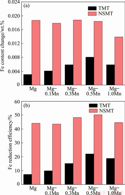
Fig. 1 Fe content change (a) and Fe reduction efficiency (b) of melt treated with different refining processes
It is generally believed that the precipitation and sedimentation of Fe and Mn atoms co-occur during the melt refining process. Since the amount of Mn added and the solubility of Mn are much higher than those of Fe, the Mn content and Fe content changes significantly exhibit different trends. Figure 2 shows the Mn content change of the melt treated with different refining processes. A positive value indicates that the Mn content is higher than the theoretical value, while a negative value indicates that the Mn content is lower than the theoretical value. It can be seen from Fig. 2 that the Mn content change varies with the Mn content and refining temperature. When it comes to the melt treated with TMT or NSMT process, the Mn content change starts to be positive and then becomes negative. Short refining time is one of the reasons for the positive value of the Mn content change. Nevertheless, with the increase of Mn content, more drastic sedimentation of Mn atoms occurs, which makes the Mn content change negative. This indicates that the consumption of Mn for removing impurities increases. Meanwhile, for the melt refining with the NSMT process, less Mn content is required to cause drastic sedimentation of Mn atoms in the melt.

Fig. 2 Mn content change of melt treated with different refining processes
3.2 Microstructure
The Fe removal effect of Mn in the magnesium scrap melt processed by the NSMT process was studied. The experiment results are shown in Fig. 3, in which the optical micrographs show the microstructure of the samples cut from the middle and bottom of cast ingot. The black spots or clusters shown in Fig. 3 correspond to Fe-rich particles. Most of the particles formed during the NSMT process can settle to the bottom of the crucible. However, these particles cannot be clearly observed in the sample cut from the middle of the cast ingot. As for 1-N alloy, some large lumps are observed in the sample cut from the bottom of the cast ingot, which can be identified as Fe-rich particle according to the EDS result shown at Point A in Fig. 3(b). In this case, Fe impurities may adhere to the surface of Mg and form a low-density mixture with Mg, and then sink together. For 4-N alloy, some oval particles are observed in the sample cut from the bottom of the cast ingot. The EDS analysis of Point B in Fig. 3(d) indicates 40.00 at.% Mn, 11.22 at.% Fe and 49.03 at.% Mg, which confirms that the particles are rich in Fe and Mn elements. Based on the above analysis, it can be concluded that the shape and size of the Fe-rich particles in the sample that cut from the bottom of the cast ingot change with the addition of Mn.
The alloy samples cut from the middle of the ingot were analyzed with a higher SEM magnification to study the microstructure evolution of the Fe-rich particles in the melt treated with NSMT process. In this work, the initial microstructure of the NSMT process alloy is regarded as the microstructure of the alloy with TMT process. Figure 4 displays the morphology of the Fe-rich particles in 1-T, 1-N, 4-T and 4-N alloys after mechanical grinding in distilled water. According to the EDS results (Table 2) of Points A-E in Fig. 4, these fine particles are considered as Fe-rich particles. The EDS line scanning results of the Fe-rich particles are shown in Fig. 5. Several Fe-rich particles with an average size of 0.24 μm are observed in the sample of 1-T, and their cores are of bright color (Fig. 5(a)). The Fe-rich particles in the sample of 4-T possess a similar structure to the 1-T sample, the inner layer is brighter and the outer layer is slightly darker. The average size of Fe-rich particles in the 4-T sample is about 0.27 μm (Fig. 4(c)). According to the EDS line scanning result, the intensity of Fe and Mn reaches the maximum peak value at the same position (the center of the brighter inner layer), and then gradually decreases together along the radial direction (Fig. 5(b)).
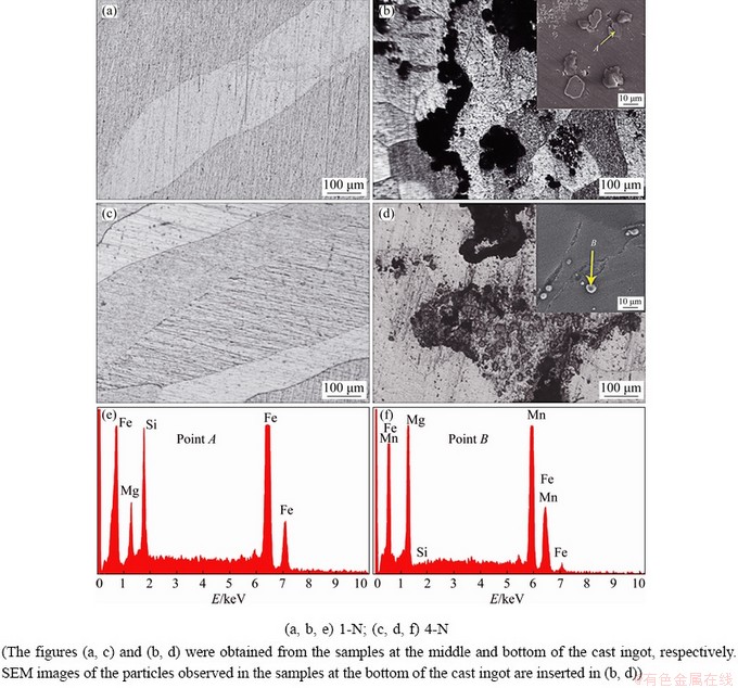
Fig. 3 Optical microstructure (a, c), SEM images (b, d) and EDS results (e, f) of samples
Obviously, after the melt refining with NSMT process, the particles become larger in size and smaller in number (Fig. 4). As for 1-N sample, the average size of Fe-rich particles is about 0.72 μm, which is 3 times that of 1-T sample. The Fe-rich particles in the 4-N sample have an average size of 0.64 μm, which is much larger than that of 4-T sample. According to the EDS line scanning results of 4-N sample, as shown in Fig. 5(c), the intensity of Fe and Mn elements reaches the peak value at the same site, and manifests the same changing trend along the radial direction of the particle. This means that the particles containing Fe and Mn elements should be a coupled growth microstructure, which has been highlighted by KIM and KOO [22]. It should be noted that after NSMT treatment, the surface of the Fe-rich particles in the 1-N and 4-N samples is much rougher than that in the 1-T and 4-T samples.

Fig. 4 SEM images of Fe-rich particles in different alloys
Table 2 EDS results of particles in different alloys shown in Fig. 4 (wt.%)

4 Discussion
4.1 Fe removal mechanism
To obtain a profound understanding of the mechanism of the Fe reduction, the solubility limit and saturation of Fe in the alloy melts refining with different refining processes are compared, as shown in Table 3. The saturation of Fe in the melt is the difference between the calculated Fe content of the raw materials and the solid solubility limit of Fe. The solubility limit of Fe element in trial samples with different Mn additions was got from Fig. 6. The calculated Fe content of the 1-T sample is as high as 0.0423 wt.%, which is lower than the solubility limit of Fe in the Mg matrix at 750 °C, but the melt still has Fe content change of 0.0031 wt.%. Due to the energy undulation of the hot melt and the existence of other elements such as Si and Ni, Fe element could precipitate out of the melt in the form of Fe-rich particles, which can settle to the bottom of the crucible. With Mn content varying from 0.1 wt.% to 0.5 wt.%, the solubility limit of Fe decreases from 0.0410 wt.% to 0.0245 wt.%, while the saturation of Fe increases from 0.0001 wt.% to 0.0121 wt.%. Namely, the driving force for the de-dissolution of Fe atoms from melt increases, so that the Fe content change increases from 0.0041 wt.% to 0.0081 wt.%. As for 5-T alloy sample, due to the addition of master alloy with low Fe impurity, the saturation of Fe is reduced, and ultimately the Fe content change is reduced.

Fig. 5 EDS line scanning results of Fe-rich particles in different alloys
Table 3 Solubility limit and saturation of Fe in alloy melt with different refining processes
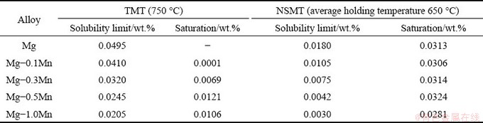

Fig. 6 Phase diagram of Mg-rich corner in Mg-Fe-Mn system [23]
The Fe content change mainly depends on the saturation of Fe in the Mg melt. Thus, the melt with NSMT process is expected to have a remarkable Fe content change. The samples of 2-N (0.1 wt.%), 3-N (0.3 wt.%) and 4-N (0.5 wt.%) alloys are equipped with almost the same saturation of Fe in the melt as 0.0306 wt.%, 0.0314 wt.% and 0.0324 wt.%, respectively (Table 3), which causes the Fe content change of the melts to remain almost constant at about 0.0180 wt.%. When more Mn (5-N sample) is added to the melt, the saturation of Fe is reduced to 0.0281 wt.%, which results in a decrease in Fe content change to 0.0139 wt.%. As for the trail melt of the 1-N sample without Mn addition, according to Table 3 and Fig. 6, when the refining temperature decreases from 750 to 650 °C, the solubility limit of Fe is sharply decreased from 0.0495 wt.% to 0.0180 wt.%. The saturation of Fe in the alloy melt of 1-A sample is as high as 0.0313 wt.%, which could lead to a higher Fe content change of 0.0187 wt.%. It is clearly found that the Fe content change of the melt without Mn addition (1-N) is almost the same as that of the melt with Mn addition from 0.1 wt.% to 0.3 wt.% and 0.5 wt.%, indicating that the NSMT process can achieve a good purification effect even if Mn is absent during the magnesium scrap melt refining process.
According to the above, a new melt process route can be developed, that is, through the NSMT process and adding an appropriate Mn content (0.3-0.5 wt.%), a relatively fixed and low level of Fe impurity can be obtained, and the other alloying elements can be added at higher temperature to finish the alloying process. Moreover, the content of alloying elements can be precisely controlled, thereby avoiding the influence of the fluctuation in the content level of Fe and other alloying elements in the alloy on microstructure and mechanical properties.
4.2 Growth of Fe-rich particles during NSMT process
During the melt refining process, the growth of the Fe-rich particles and their settling towards the bottle of crucible are critical to the purification of the melt. The average sizes of Fe-rich particles in 1-N sample (0.72 μm) and 4-N sample (0.64 μm) are much larger than those of 1-T sample (0.24 μm) and 4-T sample (0.27 μm), respectively. Figure 7 shows the schematic illustration of coarsening course of the Fe-rich particles in the melt with the NSMT process. The growth course of the Fe-rich particles during the NSMT process meets the rule of Ostwald ripening, so the size change of the particle can be described as the Ostwald ripening model [24,25].
 (3)
(3)
where r0 is the average statistic size of particles at initiating time, rt is the size at a certain Ostwald growth time t, k is the coarsening rate, α is a coarsening coefficient (α=0.47 in LSW theory [26]), R is the molar gas constant, T is the thermodynamic temperature, D0 is the diffusion constant of Fe element, V0 is the molar volume of Fe solute atom, C0 is the dissolved Fe content expressed by mass per unit volume, while Cp represents the Fe content contributed from Fe in the particles expressed by mass per unit volume and γ is the interfacial energy between Fe-rich particles and melt.
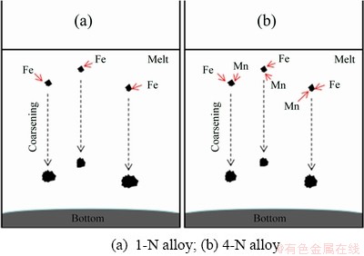
Fig. 7 Schematic illustration of coarsening course of Fe-rich particles in melt with NSMT process
The temperature (T) is critical to the coarsening rate of the Fe-rich particles. The reduction of melt temperature has a positive effect on the coarsening rate according to Eq. (3), although it can reduce the value of D0 to a certain extent. It is generally believed that the solubility of Fe decreases as the melt temperature decreases. Compared with the melt treated with the TMT process, the content of the undissolved Fe in the melt with NSMT process is much higher than that of the dissolved Fe, which is able to provide the driving force for particle coarsening. Mn addition can also influence the coarsening course. With the addition of Mn element, the solubility limit of Fe in the alloy melt is significantly reduced (Table 3). In other words, more Fe atoms can be separated from the melt and form Fe-rich particles. But in reality, the average initial size of the particles of the 1-T sample is 0.24 μm and coarsens to 0.72 μm. At the same time, by adding Mn, the average size of particles is only coarsened from 0.27 to 0.64 μm, indicating that the Mn element exerts a negative effect on the coarsening process of the Fe-rich particles in the alloy melt (Fig. 7). One of the main reasons is that the Fe-rich particles in the melt with Mn addition have a unique coupled growth microstructure (Figs. 4 and 5). With the addition of Mn, the content of the dissolved Fe decreases while the content of the undissolved Fe increases. During the NSMT process, Cp is much larger than C0, which results in a decrease of C0/(Cp-C0). Meanwhile, the addition of Mn could inhibit the diffusion of Fe element between the melt and the particles, causing the diffusion coefficient of Fe to be restrained. Therefore, Mn addition can reduce the k value of Ostwald ripening. In addition to the above two factors, the process of NSMT in this work also has a positive effect on the coarsening rate. Temperature fluctuations around the melting temperature may increase the solid phase rate in the melt, and indirectly increase the adsorption of solid phases by impurities and inclusions. Hence, the NSMT process is conductive to increase the particle size, thereby accelerating the particle sinking.
4.3 Mass loss and hydrogen evolution analysis
Figure 8 shows the relationship of the corrosion resistance (mass loss and hydrogen evolution rates) along with Fe content of alloys treated with NSMT process after being immersed in 3.5 wt.% NaCl solution for 2 d. The corrosion resistance of 1-N alloy sample is relatively weak, with a corrosion rate of 148.60±4.51 mg/(cm2・d) and a hydrogen evolution rate of 225.45± 9.62 mL/(cm2・d), which is a very low level due to the high Fe impurity level of 0.0236 wt.%. It can be clearly concluded that the higher the impurity content, the worse the corrosion resistance (Figs. 8(a) and (b)). The corrosion rate and hydrogen evolution rate both decrease sharply with the addition of Mn. When the Mn content is greater than 0.5 wt.% as 4-N and 5-N alloys, the corrosion rate (0.42-0.51 mg/(cm2・d)) and hydrogen evolution rate (0.35-0.93 mL/(cm2・d)) are just about 0.27% and 0.22% of these of the 1-N alloy, respectively. This indicates that by adding enough Mn, the corrosion sensitivity of magnesium scrap in 3.5 wt.% NaCl solution can be significantly reduced. The total Fe content in the alloy includes the dissolved Fe content (Fe solubility) and undissolved Fe content (the free Fe). But it is not clear which form of Fe plays an important role in the corrosion process.
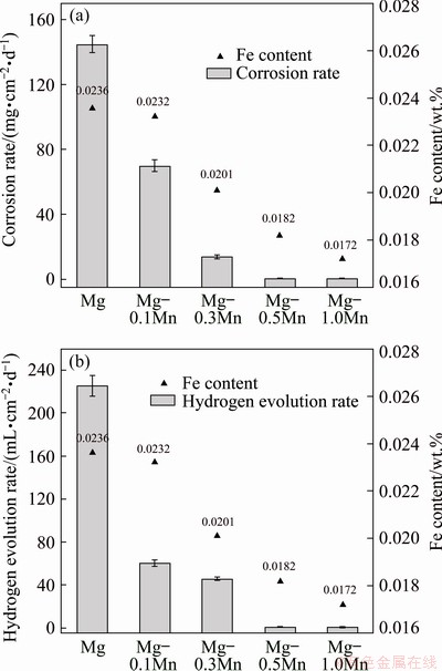
Fig. 8 Fe content and corrosion performance of alloy samples in 3.5 wt.% NaCl solution at room temperature

Fig. 9 Dissolved and undissolved Fe contents of alloy samples
Figure 9 demonstrates the dissolved and undissolved Fe content of alloy samples. When the Mn content increases from 0 to 0.1 wt.%, the solubility of Fe decreases sharply from 0.0180 wt.% to 0.0105 wt.%, while the undissolved Fe content increases from 0.0056 wt.% to 0.0127 wt.%. Nevertheless, from the data, the corrosion resistance has declined in some extent. When the Mn content increases to 0.3 wt.%, the free-Fe content remains almost unchanged, but the solid solubility Fe decreases. The decrease in the final corrosion rate is so conspicuous, and the solid solubility of Fe is considered to be the main factor affecting the corrosion rate. When the content of Mn exceeds 0.5 wt.%, the content of free-Fe remains at a high level (about 0.014 wt.%), the corrosion rate of the alloy is still at a low level, due to the low solubility of Fe (only about 0.004 wt.%). The Fe-Mn particles with a symbiotic structure could act as a barrier to the electrochemical potential difference between Mg and Fe [22], which could contribute to weaken the effect of micro-galvanic corrosion and reduce the deleterious effect of Fe impurities on the alloy. In summary, the corrosion susceptibility of the alloy mainly depends on the solubility of Fe, and the presence of abundant free-Fe (Fe-rich particles with Mn) is not a fundamental factor to accelerate the corrosion process of the alloy.
5 Conclusions
(1) The Fe content change of the melt with NSMT process is much higher than that of the traditional melt treatment process. Due to the high saturation of Fe in the melt at low treatment temperature, the purification effect of the melt with NSMT process is obvious even if the Mn is absent.
(2) The NSMT process has a positive effect on the coarsening process of the Fe-rich particles. The Mn addition increases the saturation of Fe in the melt, but the coarsening rate of Fe-rich particles during Ostwald ripening course is restrained.
(3) The corrosion susceptibility of the alloys made from magnesium scrap mainly depends on the solubility of Fe, and the solubility can be significantly reduced by Mn addition. The presence of high free-Fe content (Fe-rich particles) does not necessarily lead to severe corrosion of the alloy.
References
[1] YANG Ming-bo, CHENG Liang, PAN Fu-sheng. Comparison about effects of Ce, Sn and Gd additions on as-cast microstructure and mechanical properties of Mg-3.8Zn-2.2Ca (wt.%) magnesium alloy [J]. Journal of Materials Science, 2009, 44: 4577-4586.
[2] YEGANEH M, MOHAMMADI N. Superhydrophobic surface of Mg alloys: A review [J]. Journal of Magnesium and Alloys, 2018, 6: 59-70.
[3] WU Yi-ping, XIONG Han-qing, JIA Yu-zhen, XIE Shao-hui, LI Guo-feng. Microstructure, texture and mechanical properties of Mg-8Gd-4Y-1Nd-0.5Zr alloy prepared by pre-deformation annealing, hot compression and ageing [J]. Transactions of Nonferrous Metals Society of China, 2019, 29: 976-983.
[4] PLUMERI J E, MADEJ L, MISIOLEK W Z. Constitutive modeling and inverse analysis of the flow stress evolution during high temperature compression of a new ZE20 magnesium alloy for extrusion applications [J]. Materials Science and Engineering A, 2019, 740: 174-181.
[5] LIU Ming, SONG Guang-ling. Impurity control and corrosion resistance of magnesium-aluminum alloy [J]. Corrosion Science, 2013, 77: 143-150.
[6] CAO P, QIAN M, STJOHN D H. Effect of Fe on grain refinement of high-purity Mg-Al alloys [J]. Scripta Materialia, 2004, 51: 125-129.
[7] KARAKULAK E, KüCüKER Y B. Effect of Si addition on microstructure and wear properties of Mg-Sn as-cast alloys [J]. Journal of Magnesium and Alloys, 2018, 6: 384-389.
[8] GAO Hong-tao, WU Guo-hua, DING Wen-jiang, LIU Liu-fa, ZENG Xiao-qin, ZHU Yu-ping. Study on Fe reduction in AZ91 melt by B2O3 [J]. Materials Science and Engineering A, 2004, 368: 311-317.
[9] ZHAO Peng, GENG Hao-ran, WANG Qu-dong. Effect of melting technique on the microstructure and mechanical properties of AZ91 commercial magnesium alloys [J]. Materials Science and Engineering A, 2006, 429: 320-323.
[10] NAYEB-HASHEMI A A, CLARK J B, SWARTZENDRUBER L J. The Fe-Mg (Fe-magnesium) system [J]. Bull Alloy Phase Diagrams, 1985, 6: 235-238.
[11] LIU M, UGGOWITZER P J, SCHMUTZ P, ATRENS A. Calculated phase diagrams, Fe tolerance limits, and corrosion of Mg-Al alloys [J]. JOM, 2008, 60: 39-44.
[12] ZAINAL ABIDIN N I, MARTIN D, ATRENS A. Corrosion of high purity Mg, AZ91, ZE41 and Mg2Zn0.2Mn in Hank’s solution at room temperature [J]. Corrosion Science, 2001, 53: 3542-3556.
[13] VOLKOVA E F. Effect of Fe impurity on the phase composition, structure and properties of magnesium alloys containing manganese and aluminum [J]. Metal Science and Heat Treatment, 2017, 59: 154-160.
[14] WU Guo-hua, GAO Hong-tao, DING Wen-jiang, ZHU Yu-ping. Study on mechanism of Fe reduction in magnesium alloy melt [J]. Journal of Materials Science, 2005, 40: 6175-6180.
[15] CAO Han-xue, JIANG Hao, HUANG Yan-yan, YANG Cheng-zhi, LONG Si-yuan. A comparative study on inclusions in Mg-Nd-Zn-Zr melt employing flux and fluxless purification approach [J]. International Journal of Precision Engineering and Manufacturing, 2017, 18: 1591-1598.
[16] GANDEL D S, EASTON M A, GIBSON M A, BIRBILIS N. Influence of Mn and Zr on the corrosion of Al-free Mg alloys (Part 1): Electrochemical behavior of Mn and Zr [J]. Corrosion, 2013, 69: 666-671.
[17] CHENG Yuan-fen, DU Wen-bo, LIU Ke, FU Jun-jian, WANG Zhao-hui, LI Shu-bo, FU Jin-long. Mechanical properties and corrosion behaviors of Mg-4Zn-0.2Mn- 0.2Ca alloy after long term in vitro degradation [J]. Transactions of Nonferrous Metals Society of China, 2020, 30: 363-372.
[18] SOMEKAWA H, KINOSHITA A, KATO A. Effect of alloying elements on room temperature stretch formability in Mg alloys [J]. Materials Science and Engineering A, 2018, 732: 21-28.
[19] BRONFIN B, KATSIR M, AGHION E. Preparation and solidification features of AS21 magnesium alloy [J]. Materials Science and Engineering A, 2001, 302: 46-50.
[20] SIMANJUNTAK S, CAVANAUGH M K, GANDEL D S, EASTON M A, GIBSON M A, BIRBILIS N. The influence of Fe, manganese, and zirconium on the corrosion of magnesium: An artificial neural network approach [J]. Corrosion, 2015, 71: 199-208.
[21] PAN Fu-sheng, CHEN Xian-hua, YAN Tao, LIU Ting-ting, MAO Jian-jun, LUO Wei, WANG Qin, PENG Jian, TANG Ai-tao, JIANG Bin. A novel approach to melt purification of magnesium alloys [J]. Journal of Magnesium and Alloys, 2016, 4: 8-14.
[22] KIM J G, KOO S J. Effect of alloying elements on electrochemical properties of magnesium-based sacrificial anodes [J]. Corrosion, 2000, 56: 380-388.
[23] EFFENBERG G, ALDINGER F, ROKHLIN L. Ternary alloys [M]. Stuttgart: MSI, 1999.
[24] OHTA H, SUITO H. Effects of dissolved oxygen and size distribution on particle coarsening of deoxidation product [J]. ISIJ International, 2006, 46: 42-49.
[25] WANG Lin-zhu, YANG Shu-feng, LI Jing-she, ZHANG Shuo, JU Jian-tao. Effect of Mg addition on the refinement and homogenized distribution of inclusions in steel with different Al contents [J]. Metallurgical and Materials Transactions B, 2017, 48: 805-818.
[26] SHAHANI A J, XIAO X, SKINNER K, PETERS M. Ostwald ripening of faceted Si particles in an Al-Si-Cu melt [J]. Materials Science and Engineering A, 2016, 673: 307-320.
古东懂1,王佳文1,陈俞宾1,彭 建1,2
1. 重庆大学 材料科学与工程学院 机械传动国家重点实验室,重庆 400044;
2. 重庆市科学技术研究院 重庆市先进材料研究中心,重庆 401123
摘 要:研究由废镁加锰精炼制备的Mg-Mn合金的除铁、组织演变和腐蚀敏感性。结果表明,即使没有添加锰,近固熔(NSMT)处理也会引起显著的铁含量变化,这归因于熔体中铁的过饱和度较高。此外,在NSMT过程中,即使添加少量锰也会导致锰原子剧烈沉降。NSMT工艺可以提高富铁颗粒的生长速率,加速其沉降运动。然而,锰的加入会阻碍富铁颗粒的粗化过程。合金的腐蚀敏感性主要取决于铁的溶解度,而铁的溶解度可通过添加锰大大降低。而且,更多富铁颗粒的存在不一定会增加合金的腐蚀敏感性。因此,在由废镁制备的Mg-Mn合金的精炼过程中,基于NSMT工艺并添加合适的锰(约0.5%,质量分数)可以提高熔体的纯度,从而获得具有优异耐腐蚀性的合金。
关键词:除铁;熔体精炼处理;废镁;富铁颗粒;腐蚀敏感性
(Edited by Xiang-qun LI)
Foundation item: Project (2016YFB0301100) supported by the National Key Research and Development Program of China; Project (2018CDJDCD0001) supported by the Fundamental Research Funds for the Central Universities, China
Corresponding author: Jian PENG; Tel: +86-23-65112291; E-mail: jpeng@cqu.edu.cn
DOI: 10.1016/S1003-6326(20)65433-4

