J. Cent. South Univ. (2016) 23: 750-756
DOI: 10.1007/s11771-016-3120-2

Laboratory investigation of axisymmetric single vacuum well point
VU Van-tuan(武文俊)1, 2, YAO Lei-hua(姚磊华)1, WEI Ying-jie(魏英杰)1
1. School of Engineering and Technology, China University of Geosciences (Beijing), Beijing 100083, China;
2. Department of Civil Engineering, Le Quy Don Technical University, Ha Noi, Viet Nam
 Central South University Press and Springer-Verlag Berlin Heidelberg 2016
Abstract: Vacuum well point is a new but faint soft ground treatment method. This work focuses on the consolidation behavior of a reconstituted soft clayey specimen under vacuum well point combined with surcharge loading. The laboratory test was conducted through a vacuum-surcharge consolidation apparatus, and the vacuum loading scheme was adopted for vacuum pressure application to investigate the vacuum effect on soil consolidation. In the testing process, some key parameters such as vacuum pressure, pore water pressure and settlement deformation were timely recorded. Furthermore, the water content, void ratio and permeability coefficient of samples collected after loading were measured to reflect the consolidation characteristics. By comparing with the membrane system and membraneless system, something different was found for the vacuum well point method. The results indicate that the consolidation behavior of an axisymmetric single vacuum well point is almost identical to the behavior of vacuum preloading combined with prefabricated vertical drain (PVD), except for the distribution of the vacuum pressure along the well drain due to the structure of the vacuum well point. And the vacuum well point method may be useful for the improvement of soft clayey deposit in a certain depth.
Key words: soft ground; vacuum consolidation; vacuum well point systems; vacuum pressure
1 Introduction
Vacuum consolidation as a highly-efficient and environmentally friendly ground treatment method was creatively proposed by KJELLMAN [1] in the early 1950s and has been developing rapidly for more than 60 years. Up to date, it has received more and more attention and intensive laboratory research and numerical analysis are ongoing [2-5]. Meanwhile, it has been used widely in practice due to its enormous advantages [6-9].
Prefabricated vertical drain (PVD) as a useful tool combined with vacuum preloading spreads rapidly and has been studied deeply recently. CHAI et al [10] deemed that the evaluation of vacuum pressure distribution which has significant influence on the calculation of ground deformation is vital in consolidation projects. ABDUL and MESRI [11] investigated the vacuum distribution with depth in vertical drains and soil preloading. INDRARATNA et al [12] studied the soft ground improvement via vertical drains in combination with vacuum preloading by using the spectral method and finite element analysis. SAOWAPAKPIBOON et al [13] conducted the study of single PVD and vacuum-PVD for reconstituted specimen and the results were simulated by 2D (axisymmetric) finite element method (FEM) to back-analyze the related design parameters, finding that the vacuum-PVD is more efficient than a single PVD. And GENG et al [14] presented analytical solutions of vertical drains with vacuum preloading for membrane and membraneless systems under time-dependent surcharge preloading by assuming that the vacuum pressure in membraneless system decreased along the drain, whereas it remained constant in membrane system. The results indicated that the assumption is reasonable.
Corresponding to vacuum-PVD method, vacuum well point as a new and effective soft ground treatment technique is receiving more attention.
XIE et al [15] analyzed the function and contribution of the new method in accelerating consolidation, reducing after-work settlement, and decreasing longitudinal gradient variation ratio. WANG and ZHAI [16] studied the characteristics of stress and deformation in the bridge-slope subgrade reinforced by vacuum well point dewatering combined with equal preload and proved that well point method is reasonable as well as economical in settlement treatment, compared with conventional grouting method. Based on the practical engineering data, YANG et al [17] proposed that vacuum well point dewatering and preloading can increase not only the degree and rate of consolidation, but also the stability of side slope and soil. LE et al [18] investigated the characteristics of filter and found that the clogging was related to the soft clay as well as the production technology. Enormous advantages have been proved, whereas the consolidation behavior of vacuum well point has not been studied deeply and the relationship between vacuum well point and vacuum- PVD was not clear yet.
In this work, the laboratory investigation test of an axisymmetric single vacuum well point was conducted by a vacuum-surcharge apparatus. Some key parameters which can reflect the characteristics of vacuum well point were taken into account, and the effects of vacuum pressure in consolidation were investigated. Furthermore, the differences between the similar treatment methods, vacuum-PVD and vacuum well point, were analyzed so as to conduct engineering application.
2 Laboratory model test
2.1 Vacuum-surcharge consolidation apparatus
The vacuum-surcharge consolidation apparatus shown in Fig. 1 was used to simulate the behavior of soft clayey deposit under loading-unloading conditions.
The chamber called sample tank was made of polymethyl methacrylate with dimensions of 1.0 m in height, 0.44 m in internal diameter and 0.5 m in outer diameter. Two stainless steel circular sheets, 30 mm in thickness, were selected to make the bottom pedestal as well as the top one. And eight steel rods, 20 mm in diameter, were used to connect the bottom and the top pedestal for stability and safety. A piston with 40 mm in thickness and a hollow shaft with 150 mm in outside diameter were combined together for piston loading system. Around the shaft was a guide, and it enabled the piston to move in the straightway without tilting. Different sealing methods were adopted strictly among all parts. “O” rings, made of synthetic rubber, were used to seal the small gaps between the cylinder cell and the piston, the top pedestal and the shaft, the shaft and the guide. To increase lubrication, silicone grease was applied to the “O” rings’ and the internal surface of the chamber to reduce soil friction. Clogging problems of the loading piston can be avoided by using geotextiles on top of the soil specimen. The air pressure was loaded on the top of the piston through a natural rubber membrane while the vacuum pressure was applied to the vacuum well point through a small and special cylindrical tank which can separate the water and the air. The vacuum pressure was generated through the vacuum generator which was directly connected to the air pump.

Fig. 1 Schematic diagrams of vacuum-surcharge consolidation apparatus and sampling locations (unit: mm):
The sealing space formed by piston and hollow shaft is the loading system. It is more convenient to apply different surcharge pressures. Although different sealing methods were adopted strictly among the parts, the sealing still was not perfect. Therefore, the behavior of soil layer in soil sample tank can be considered as a unit cell closer to the field conditions.
A pressure gauge was used to measure the surcharge loading pressure value. The settlement of soil specimen was measured by a dial gauge which was located at the top of the shaft. Six piezometers were placed at various points in the cell to measure pore water pressures, as shown in Fig. 1(a). A system of a digital data logger connected to a computer was used to monitor the pore water pressure during the test.
2.2 Vacuum well in test
The vacuum well point consisted of one PVC tube, with 25 mm in outside diameter and 0.65 m in length, in the middle and a layer of coarse sand wrapped outside the PVC tube. In order to restrict the horizontal displacement of the vacuum well, a stainless steel net was wrapped around the sand. And to avoid clogging problem during the test, geotextiles were used at the well point filter as well as the stainless steel net.
In order to investigate the distribution of the vacuum pressure in the vacuum well, two vacuum gauges were installed. And the schematic diagram is shown in Fig. 1(a).
2.3 Process of laboratory test
2.3.1 Preparation of reconstituted clay
The soft clay samples used in the test were collected from 1.0 to 2.0 m depth in Tianjin, China, a coastal city about 120 km southeast of Beijing. In the laboratory, the clay samples were mixed with sufficient amount of water in a mechanical mixer, making sure that the water content of the remolded samples was 1.2 times as the clay samples’ saturation limit and the properties were as close to as those of the undisturbed soil.
Afterwards, initial preloading phase was carried out as follows: 1) A thin layer of silicon grease was applied on the internal surface of chamber to reduce friction between soil sample and the cylinder cell. 2) The vacuum well was put in the centerline of the chamber and the remolded samples would be moved in layers with the thickness of about 0.05 m, after which a vibrator was used to remove the air bubbles in each layer until the total thickness was up to 0.8 m. The piezometers were installed at the predetermined heights simultaneously. 3) The loading system and pedestal etc were mounted subsequently and testing instruments, such as dial gauge, pressure gauge and vacuum pressure gauge were installed. After that, 4) preloading pressure of 10 kPa was applied to prepare the reconstituted specimens through the air pressure system and some soil properties of reconstituted clay sample were tested before vacuum- surcharge consolidation, as listed in Table 1.
Table 1 Soil properties of reconstituted clay sample

2.3.2 Loading and monitoring
To investigate the properties of the soft clay under different vacuum pressures combined with surcharge pressure conditions, an air pressure system was built to simulate the surcharge pressure. Before tests, the soil sample was preloaded for six days under 10 kPa surcharge pressure. Then, the surcharge pressure was kept at 25 kPa constantly and the vacuum pressure value was set to be 50 kPa. The effects of vacuum reloading and unloading were investigated by releasing the vacuum pressure once during the testing time. Test loading scheme is listed in Table 2.
Table 2 Summary of loading for laboratory test

2.3.3 Sampling and tests after consolidation
Horizontal and vertical specimens were collected at different locations in the cell (i.e. Sections A, Section B and Section C shown in Fig. 1) at the end of test. All the samples were measured to establish the water content, the void ratio, and the permeability coefficient.
3 Test results and analysis
3.1 Distribution of vacuum pressure in vacuum well
The distribution of vacuum pressure along the vacuum well drain is different from the distribution of vacuum pressure along the PVD in a membrane system (with an airtight membrane over the drainage layer) and a membraneless system [18]. The vacuum pressure value in a membrane system decreases towards the bottom of the PVD (Fig. 2(a)) and in the membraneless system it is maintained at a constant level (Fig. 2(b)). It can be seen from Fig. 2(c) that vacuum pressure value in the well point reaches the maximum at Point A and maintains the level to the bottom of the well drain; however, the vacuum pressure value diminishes from Point A toward the top of the well drain.
3.2 Variation of water content and void ratio as well as permeability coefficient
Table 3 gives the soil properties of the small specimens at different locations in the cell at the end of the test. The variation of void ratio and the decrease in water content at Section A, B and C with the radial distance are shown in Figs. 3(a) and (b), respectively. The results show that the nearer a specimen gets to the well point, the more its water content decreases, and the same variation law is found for the void ratio and the permeability coefficients. In other words, the permeability coefficients decrease towards the vicinity of the drain (Figs. 3(c) and (d)). And these behaviors are consistent with principles of vacuum consolidation of soft clay via vertical drain.
3.3 Analysis of excess pore water pressure
It can be seen from the measured pore water pressure shown in Fig. 4 that the application of 50 kPa vacuum pressure via a vacuum well point is proven to be beneficial for speeding up consolidation. After surcharge loading, the excess pore pressure immediately increases to the maximum, and decreases quickly to 8-14 kPa in the first 8 h with the assistance of vacuum pressure. The excess pore water pressure is reduced more slowly in 11 h while the vacuum pressure is unloaded, and then decreases rapidly again in the next 36 h when the vacuum pressure is reloaded.
The correlation between the distribution of vacuum value along vacuum well point and the pore water pressure value at various points in the cell can be observed by obtaining the pore water pressure values of the piezometers. As shown in Fig. 4(a), the pore water pressure of piezometer No. 3 is smaller than that of the No. 5 at the end of testing time, indicating that the lower the piezometer is installed, the larger the vacuum pressure it attains. The behavior is proven also by piezometer No. 4 and No. 6.
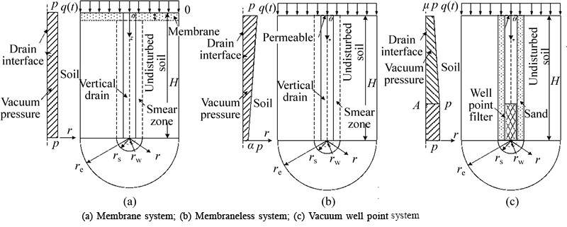
Fig. 2 Analysis schemes of unit cell with vertical drain:
Table 3 Soil properties at end of test

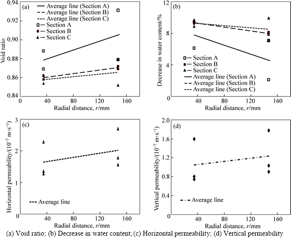
Fig. 3 Water content, void ratio and permeability coefficient at different radial distances:

Fig. 4 Variation of excess pore water pressure with time:
The pore water pressure value, on the other hand, is also influenced by the distance from the vacuum well point. In the same horizontal plane, the pore water pressure value becomes smaller as the test point gets closer to the vacuum well point. It can be proven through the pore water pressure value of piezometers: the pore water pressure value on No. 1 is smaller than that on No. 2, the value on piezometer No. 3 is smaller than that on No. 4 and the value on piezometer No. 5 is smaller than that on No. 6, as shown in Figs. 4(b)-(d).
3.4 Analysis of consolidation settlement
As plotted in Fig. 5, the variation of settlement with time is the same as the variation of the pore water pressure: 1) The settlement value increases rapidly in the first 8 h with the assistance of vacuum pressure and reaches 10.97 mm. 2) In the next 11 h, when the vacuum pressure is unloaded, the settlement value increases slowly, with an increment of 2.95 mm only. 3) The settlement rate gets higher again when the vacuum pressure is reloaded in the next 36 h; however, this settlement rate is smaller than that of the first 8 h, and the settlement increases to 14.76 mm during this time.

Fig. 5 Variation of settlement with time
4 Conclusions
The laboratory test was conducted to investigate the consolidation behavior of an axisymmetric single vacuum well point. Based on the test results, the following conclusions can be obtained.
1) The distribution of vacuum pressure along the vacuum well is different from that of the PVD in membrane system and membraneless system. The vacuum pressure in the well increases linearly with depth and reaches the maximum at the top of the filter and remains constant to the bottom.
2) The consolidation behavior of a single vacuum well point is almost identical to that of a single PVD incorporated with vacuum preloading. However, for points located at a similar horizontal distance in vacuum well point, the lower the position, the smaller the pore water pressure. Vacuum-PVD is opposite.
3) The effects of vacuum unloading and reloading show that the vacuum pressure in vacuum dewatering well has remarkable effect on the drainage of pore water and the soil consolidation process. The vacuum well point could be an effective method for the improvement of soft clayey deposit in a certain depth due to its characteristics.
References
[1] KJELLMAN W. Consolidation of clay soil by atmospheric pressure [C]// Proceedings of a Conference on Soil Stabilization. Boston, USA: Mssachusetts Institute of Technology, 1952: 258-263.
[2] PENG Jie, XIONG Xiong, MAHFOUZ A H, SONG En-run. Vacuum preloading combined electroosmotic strengthening of ultra-soft soil [J]. Journal of Central South University, 2013, 20(11): 3282-3295.
[3] WU Hui, HU Li-ming. Numerical model of soft ground improvement by vertical drain combined with vacuum preloading [J]. Journal of Central South University, 2013, 20(7): 2066-2071.
[4] ROBINSON R G, INDRARATNA B, RUJIKIATKAMJORN C. Final state of soils under vacuum preloading [J]. Canadian Geotechnical Journal, 2013, 49(6): 729-739.
[5] LE G L, BERGADO D T, TAKENORI H. PVD improvement of soft Bangkok clay with and without vacuum preloading using analytical and numerical analyses [J]. Geotextiles and Geomembranes, 2015, 43(6): 547-557.
[6] CHAI J, RONDONUWU S G. Surcharge loading rate for minimizing lateral displacement of PVD improved deposit with vacuum pressure [J]. Geotextiles and Geomembranes, 2015, 43(6): 558-566.
[7] ONG C, CHAI J, HINO T. Degree of consolidation of clayey deposit with partially penetrating vertical drains [J]. Geotextiles and Geomembranes, 2012, 34(10): 19-27.
[8] QUANG N D, GIAO P H. Improvement of soft clay at a site in the Mekong Delta by vacuum preloading [J]. Geomechanics and Engineering, 2014, 6(5): 419-436.
[9] TOSHIFUMI S, AKIRA M, MAKOTO F. Prediction of embankment behavior of regulating reservoir with foundation improved by vacuum consolidation method [J]. Soils and Foundations, 2014, 54(5): 938-954.
[10] CHAI J C, HONG Z S, SHEN S L. Vacuum-drain consolidation induced pressure distribution and ground deformation [J]. Geotextiles and Geomembranes, 2010, 28(6): 525-535.
[11] ABDUL Q K, MESRI G. Vacuum distribution with depth in vertical drains and soil during preloading [J]. Geomechanics and Engineering, 2014, 6(4): 377-389.
[12] INDRARATNA B, RUJIKIATKAMJORN C, BALASUBRAMANIAM A, MCINTOSH G. Soft ground improvement via vertical drains and vacuum assisted preloading [J]. Geotextiles and Geomembranes, 2012, 30(4): 16-23.
[13] SAOWAPAKPIBOON J, BERGADO D, VOOTTIPRUEX P, LAM L, NAKAKUMA K. PVD improvement combined with surcharge and vacuum preloading including simulations [J]. Geotextiles and Geomembranes, 2011, 29(1): 74-82.
[14] GENG X, INDRARATNA B, RUJIKIATKAMJORN C. Analytical solutions for a single vertical drain with vacuum and time-dependent surcharge preloading in membrane and membraneless systems [J]. International Journal of Geomechanics, 2010, 12(1): 27-42.
[15] XIE Hong-shuai, ZAI Jin-zhang, LIU Qing-hua, LIU Pu. Study of technology of soft subsoil under freeway bridge embankment by the combined-preloading of vacuum dewatering and loading [J]. China Journal of Highway and Transport, 2003, 16(2): 27-30. (in Chinese)
[16] WANG Zhong-wei, ZAI Jin-zhang. Research on comparative tests of reinforcement for bridge-slope subgrade by vacuum wellpoint dewatering combined with equal preload [J]. Chinese Journal of Rock Mechanics and Engineering, 2004, 25(15): 2579-2584. (in Chinese)
[17] YANG Hai-xu, WANG Hai-biao, DONG Xi-bin. Experimental study on the combined method of vacuum well point dewatering and preloading [J]. Journal of Harbin Institute of Technology, 2008, 40(12): 2044-2047. (in Chinese)
[18] LE Chao, XU Chao, WU Xue-feng, JIN Ya-wei. Experimental research on clogging characteristic of two types of PVD filters [J]. Rock and Soil Mechanics, 2014, 35(9): 2529-2534. (in Chinese)
(Edited by YANG Bing)
Foundation item: Projects(41202220, 41472278) supported by the National Natural Science Foundation of China; Project(20120022120003) supported by the Research Fund for the Doctoral Program of Higher Education, China; Project(2652012065) supported by the Fundamental Research Funds for Central Universities, China
Received date: 2015-05-25; Accepted date: 2015-08-10
Corresponding author: VU Van-tuan, PhD Candidate; Tel: +86-13439242305; E-mail: vutuan2601@yahoo.com

