Dynamic engagement characteristics of wet clutch based on hydro-mechanical continuously variable transmission
来源期刊:中南大学学报(英文版)2021年第5期
论文作者:肖茂华 赵静 Petr BARTOS Andrea BOHATA
文章页码:1377 - 1389
Key words:wet clutch; friction heat; friction torque; friction power
Abstract: The effect of the design parameter on the clutch engagement process of the hydro-mechanical continuously variable transmission (CVT) was investigated. First, the model of the power train was developed with the software of SimulationX, and the clutch shift experiment was used to validate the correctness of the model. Then, the friction coefficient function was fitted with the test data to get the friction coefficient model suitable for this paper. Finally, based on the evaluating index of the friction torque and the friction power, two groups of design parameters (oil pressure and friction coefficient) were simulated and explained the changing regulation theoretically. According to the simulation results, the high oil pressure and friction coefficient can reduce the slipping time. The large oil pressure can increase the peak torque but the effect of friction coefficient on the peak torque is not so significant. The friction power reaches the maximum value at 3.2 s, the peak value increases as the oil pressure and friction coefficient increase. The effect of the oil pressure on the clutch engagement and thermal performance is greater than the friction coefficient.
Cite this article as: ZHAO Jing, XIAO Mao-hua, Petr BARTOS, Andrea BOHATA. Dynamic engagement characteristics of wet clutch based on hydro-mechanical continuously variable transmission [J]. Journal of Central South University, 2021, 28(5): 1377-1389. DOI: https://doi.org/10.1007/s11771-021-4709-7.

J. Cent. South Univ. (2021) 28: 1377-1389
DOI: https://doi.org/10.1007/s11771-021-4709-7

ZHAO Jing(赵静)1, XIAO Mao-hua(肖茂华)1, Petr BARTOS2, Andrea BOHATA2
1. College of Engineering, Nanjing Agricultural University, Nanjing 210031, China;
2. Faculty of Agriculture, University of South Bohemia, Studentska 1668, Czech
 Central South University Press and Springer-Verlag GmbH Germany, part of Springer Nature 2021
Abstract: The effect of the design parameter on the clutch engagement process of the hydro-mechanical continuously variable transmission (CVT) was investigated. First, the model of the power train was developed with the software of SimulationX, and the clutch shift experiment was used to validate the correctness of the model. Then, the friction coefficient function was fitted with the test data to get the friction coefficient model suitable for this paper. Finally, based on the evaluating index of the friction torque and the friction power, two groups of design parameters (oil pressure and friction coefficient) were simulated and explained the changing regulation theoretically. According to the simulation results, the high oil pressure and friction coefficient can reduce the slipping time. The large oil pressure can increase the peak torque but the effect of friction coefficient on the peak torque is not so significant. The friction power reaches the maximum value at 3.2 s, the peak value increases as the oil pressure and friction coefficient increase. The effect of the oil pressure on the clutch engagement and thermal performance is greater than the friction coefficient.
Key words: wet clutch; friction heat; friction torque; friction power
Cite this article as: ZHAO Jing, XIAO Mao-hua, Petr BARTOS, Andrea BOHATA. Dynamic engagement characteristics of wet clutch based on hydro-mechanical continuously variable transmission [J]. Journal of Central South University, 2021, 28(5): 1377-1389. DOI: https://doi.org/10.1007/s11771-021-4709-7.
1 Introduction
Tractor plays a key role in farm mechanization and has proved to be a versatile machine both for agriculture and farmer, and has become a major source of income during the off season [1]. The complex agricultural operating conditions lead to excessive gear shifting, this repeated gear shifting generates the friction heat and reduces the life of clutch due to the engagement and disengagement cycles [2, 3]. During the start and shift of the tractor, the wet clutch transmits torque by slipping between the friction disc and the steel sheet. Because of the friction heat, it is easy to cause the temperature gradient of the friction surface to be too large and cause permanent failure. This will reduce the clutch reliability, which determines the safety of the entire tractor [4-7]. In the working process of wet clutch, it is important to clarify the changing regulations of various influencing factors for the performance research, structural optimization and malfunction prevention of clutch. Researches on the friction characteristics of wet clutches started earlier and have achieved a lot of research results. The rough contact model proposed by GREENWOOD et al [8] was developed based on the elastic contact theory. LI et al [9] proposed a method for predicting the wear of wet clutches in friction linings after repeated meshing cycles. They pointed out that the wear mechanism and thermal degradation were related to mechanical effects. The prediction model was based on the “two-stage” wear rate phenomenon observed in experiments reported in the recent literature. KANDA [10] added 6 different additives to the lubricating oil of the automatic transmission to change the friction coefficient of the clutch friction pair. Studies had shown that only the addition of sulfur-based friction materials can increase the friction coefficient by 30% [10]. ZHANG et al [11] and WEI et al [12] used laser pulses to engrave micro-textures with different patterns, depths and pitches on the paper-based friction material of the wet clutch friction disc, and used the SAE#2 test bench to research the friction characteristics. The test results showed that after engraving these tiny grooves, the dynamic friction coefficient under low temperature and low pressure conditions was significantly improved. ZHAO et al [13] established a micro-hybrid model of friction pairs based on the local lubrication and friction characteristics of the wet clutch. The friction wear test was used to analyze the change of friction coefficient of the friction disc at different speeds roughly corresponds to the actual contact area of the micro-convex peaks. On the basis of analyzing the mechanical structure of the continuously variable transmission wet clutch, ZHANG et al [14] established the mathematical model of the wet clutch and studied the influence of different dynamic friction coefficient slopes on clutch friction torque. FENG [15] completed the dynamic nonlinear model of the clutch engagement process, and studied the dynamic regulation of friction coefficient in a targeted manner, and experimentally studied the clutch working process during the vehicle starting process. ZHU [16] studied the friction torque characteristics of the friction pairs from the perspective of friction work and friction power during the engagement of the wet clutch, and built a test bench to determine the friction work and friction coefficient of the wet clutch. Aiming at four different shift types, LU et al [17] set up the ideal characteristics of shift clutch. By using torque estimation method, PI slip control algorithm and engine coordinated control principle, the control model and transmission controller were well developed for three shift phases which included rapid-fill phase, torque phase and inertia phase. The severe wear of separating ring is considered to be a main reason which leads to the improper declutch of the main clutch of heavy vehicles. SUN et al [18] employed scanning electron microscopy and transmission electron microscopy to analyze the surface features and dislocation characteristics of the separating ring.The results show that the failure of separating ring results from the impact wear and grain-abrasion together with the plastic deformation.
In recent years, the research on the working performance of wet clutches has mainly focused on the new lubricating oil groove structure, lubricating oil types and new friction materials, but the theoretical models built for wet clutches have not considered the transmission components such as engine, transmission and load. Besides, the friction coefficient calculation model of the friction disc, which plays a key role when the wet clutch works, is also not accurate enough.
2 Principle of hydro-mechanical CVT
The principle of the hydro-mechanical CVT is shown in Figure 1. The main components include a wet clutch, a variable pump-quantity motor hydraulic system and a power split and confluent structure composed of planetary gear and fixed shaft gear [19]. The transmission can reach a top tractor speed of 50 km/h with a maximum hydraulic power split ratio.
Except hydraulic range H0 (which is controlled by clutch k0) for tractor starting up, the engine is split into hydraulic and mechanical part in range HM1-HM2 (which are controlled by clutch k0-k2, respectively). When the transmission runs at range HM0, the power of the entire power train is provided by the engine and the pump-motor, and the planetary row does not participate in this work, which marked with a red line. When the transmission runs at range HM1, the hydraulic (a blue line) and mechanical (a red line) powers flow into the plant carrier and sun gear of p1, respectively, and bring together in the ring gear. Correspondingly, when the transmission runs at range HM2, the hydraulic (a blue line) and mechanical (a red line) powers flow into the ring gear and sun gear of p2, respectively, and bring together in the plant carrier.
Figure 2 shows the hydraulic control system of the wet clutches. Taking the shift process from range HM1 to HM2 as an example: when the solenoid valve c2 is engaged first, the hydraulic oil flows into the cylinder of the wet clutch k2 to propel the piston of the cylinder, which will compact the steel sheets and friction disks of clutch k2 to transmit friction torque. After a period of short delay to avoid power interruption, the controller cuts off the power of solenoid valve c1, and then, the return spring separates the steel sheets and friction disks of clutch k1 to terminate the power transmission from this clutch.
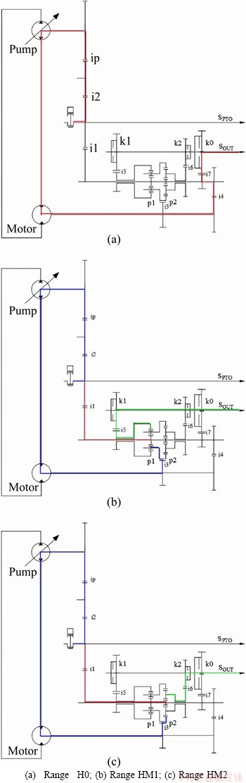
Figure 1 Schematic diagram of hydro-mechanical continuously variable transmission:(Note: p1-p2 are plant gears; k0-k2 are clutches; SPTO is input shaft; SOUT is output shaft)
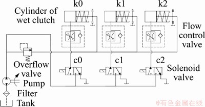
Figure 2 Schematic diagram of clutches control system
3 Equivalent dynamic model
HMCVT is a complex system. In order to facilitate modeling, HMCVT is simplified as shown in Figure 3 [20]. In the figure, k0-k2 represent the wet clutches; p1 and p2 represent the planetary gears; subscripts r, j and s represent the ring gear, planet carrier and sun gear of the planetary gear; subscripts p and m represent the PV(variable displacement pump) and MF(fixed displacement motor).

Figure 3 Equivalent dynamic model of HMCVT
When simplifying, the two shafts of the fixed gear transmission are equivalent to the same shaft, and the rotational inertia and torque of the fixed gear transmission are equivalent to the ring gear and planet carrier of the planetary gear [21]. The rotational inertia of each gear and shaft are calculated in Pro/E, and the rotational inertia of each equivalent shaft are obtained according to the equivalent conversion principle and the equivalent dynamic model.
The torque transfer dynamic model of the wet clutch is shown in Figure 4.

Figure 4 Clutch engagement dynamic model
The model is a mechanical system with two degrees of freedom, comprising two rotational inertias I1 and I2, two unequal angular velocities ω1 and ω2 and loaded by torques Tin and Tout. The load on the friction surface of the wet clutch is applied by Fn, which is provided by the oil pressure P from the solenoid valve during engagement and disengagement.
4 Modelling and experimental validation
4.1 Induction of power train
The experimental power train consists of a diesel engine, a hydro-mechanical CVT, a magnetic powder brake, speed & torque sensors and a clutches control system, as shown in Figure 5. The diesel engine supplied the driving power, the magnetic powder brake acted as a power absorber, the speed & torque sensors were used to get the speed and torque data of the engine and transmission, and the clutches control system was used to conduct the power shift of the transmission [22]. In order to control the transmission and the magnetic powder brake, a remote control system was developed based on Matlab/GUI and Single Chip Microcomputer system further.
4.2 Mathematical model of power train
When clutch engaged at a range, two or more shafts were connected to rotate together, the dynamic model can be described as follows:
1) When in HM1 range, clutch k1 engaged.
1-s1-s2 connected shaft (Take the red line in Figure 3 as an example):
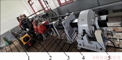
Figure 5 Power train for experiments of shift process (1-Clutch control system; 2-Engine; 3-Hydro-mechanical CVT; 4-Speed & torque sensor; 5-Magnetic powder brake)
 (1)
(1)
 (2)
(2)
 (3)
(3)
 (4)
(4)
 (5)
(5)
r1-j2-2 connected shaft:
 (6)
(6)
 (7)
(7)
 (8)
(8)
 (9)
(9)
where ωE is engine rotation speed; ωin is input shaft rotation speed; ωs1 is the sun gear rotation speed of p1 planetary gear; ωs2 is the sun gear rotation speed of p2 planetary gear; JE is the inertia moment of the engine; J1 is inertia moment of input shaft; Js1 is inertia moment of the sun gear of p1 planetary gear; Js2 is inertia moment of the sun gear of p2 planetary gear; TEp is the equivalent torque of the joint shaft active part in the same direction as ωE ; TEn is the equivalent torque of the joint shaft active part in the opposite direction as ωE.
2) When in HM2 range, clutch k2 engaged
1-j1-r2 connected shaft:
(10)
(11)
(12)
(13)
 (14)
(14)
where Tp is the torque of the variable pump; ip is the transmission ratio of the variable pump; Ts1 is the torque of the sun gear of p1 planetary gear; Ts2 is the torque of the sun gear of p2 planetary gear.
R1-j2-2 connected shaft:
 (15)
(15)
 (16)
(16)
 (17)
(17)
 (18)
(18)
When transmission shifted from a range to another, two range clutches enter the stage of slipping, the dynamic model is given as follows [23, 24]:
 (19)
(19)
 (20)
(20)
 (21)
(21)
 (22)
(22)
where I1 and I2 are rotational inertia of driving and driven shaft of clutch, kg・m2; ω1 and ω2 are angular velocity of driving and driven shaft of clutch, rad/s; Tin and Tout are torques of driving and driven shaft of clutch, N・m; Tf is friction torque, N・m; τ is number of friction surfaces; r0 and ri are outer and inner diameter of friction surfaces, mm; Fn is press-on force of clutch, N; μ(ω) is actual speed-dependent friction coefficient; p is oil pressure, MPa; A is equivalent area of piston, mm2; B is stiffness of return spring, N/mm; y is displacement of return spring, mm; y0 is initial displacement of return spring, mm.
Under normal circumstances, the relatively high slipping speed of the clutch not only raises the temperature of the friction surfaces, but also causes scratches and flaking of the friction material on the engagement surfaces, and even causes chemical changes, which seriously affect the friction coefficient [25]. In the past studies, the friction coefficient of the clutch was generally constant, which could not accurately reflect the dynamic engagement characteristics of the clutch.
The friction material of the clutch used in this work is copper-based powder metallurgy, which has a high comprehensive friction coefficient and can maintain good friction performance in a large temperature range. Combined with the Stribeck curve, the friction coefficient calculation equation that satisfies the Stribeck curve can be fitted [26]. Since the effect of the Newtonian internal friction generated by the viscosity of the lubricating oil during the wet clutch engagement is extremely small with respect to the microprotrusion contact, so it can be ignored [27]. Then the Stribeck equation can be simplified to:
 (23)
(23)
where μs is the sticking friction coefficient; μc is the slipping friction coefficient; ω is the relative slipping angular velocity, σ and ωs are the velocity parameters describing the Stribeck equation fitted according to the experimental data.
The friction plate used in the test is the radial groove copper-based friction plate produced by Shanghai Yuyi Machinery Co., Ltd., China. The experimental data are provided by the company. When the engagement pressure is 2 MPa and the engagement temperature is 60 °C, the slipping friction coefficient and the sticking friction coefficient of the copper-based friction material from the manufacturer are 0.04 and 0.14, respectively.
The Stribeck simplified equation is used as the fitting objective function. According to the nonlinear curve fitting method, the relationship between the friction coefficient and the relative slipping angle velocity of the clutch is as follows:
 (24)
(24)
The experiment and simulation friction coefficient curves of the clutch are shown in Figure 6.
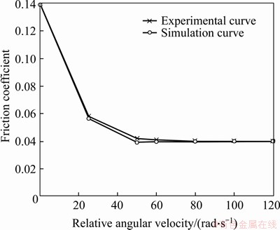
Figure 6 Experiment and simulation friction coefficient curves
It can be seen from Figure 6 that the simulation curve of the friction coefficient is basically consistent with the experimental curve, which shows that the friction equation fitted by numerical simulation is correct. The friction coefficient of the clutch has a maximum value when the relative slipping angle velocity is 0, which is equal to the sticking friction coefficient. When the relative slipping angle velocity reaches 50 rad/s, the friction coefficient is maintained at the slipping friction coefficient and is basically unchanged later.
4.3 Whole model
Based on the theoretical analysis above, the power train was modeled under the commercial software SimulationX including engine, hydro-mechanical CVT and load, as shown in Figure 7.
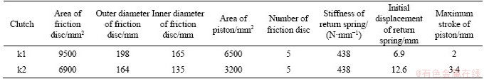
In this model, the values of rotational inertia were calculated by the software of Pro/E and converted to adjacent shafts in view of the complex structure of these components; the press-on force Fn was calculated by the model of clutches control system according to Eq.(8). Other properties of the power train component such as the geometric parameters of gears and wet clutches were obtained from the drawing of transmission or provided by the manufacturer. Part of the parameters the model used are shown in Tables 1 and 2.
4.4 Validation of simulation model
In order to verify the reliability of the power train model, the clutch shift test program was designed [28]. The simulation results are shown in Figure 8, the results indicate that the oil pressure simulated basically tallies with the results measured.
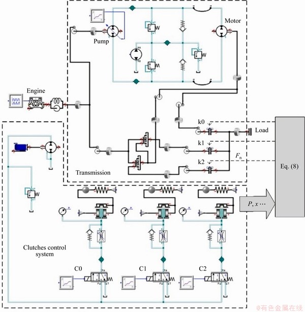
Figure 7 Model of power train with SimulationX (Note: Fn is press-on force of clutch, N; p is oil pressure, MPa; x is displacement of return spring, mm)
Table 1 HMCVT transmission ratio

Table 2 Geometric parameters of wet clutches
It can be seen from Figure 8 that it takes about 0.5 s from clutch k1 start to drain to clutch k2 full charge. However, due to the leakage and pressure loss during oil transmission in the test bench, the experiment curve will be slightly less than simulated oil pressure after the engagement is stabilized, and the different stiffness of the return springs affects the oil filling and draining time.
Besides, Figure 8(a) shows the results of a simulation process, and the time setting is set according to the different theoretical time of the whole machine. The previous running time of the whole machine is superimposed. Figure 8(b) shows the results of the bench test. The section change test is directly carried out, so the two horizontal coordinate ranges are different.
5 Simulation of friction torque
After the model of the power train is established, the oil-filled pressure range is determined through preliminary experiments. When the oil-filling pressure is lower than 3 MPa, the transmission torque of the clutch cannot be guaranteed; when the oil-filling pressure is higher than 6 MPa, the friction pairs suffer deformation and damage. These working conditions are not conducive to the stable operation of the clutch. Other simulation conditions are set as follows: engine output speed is set to 2200 r/min, wet clutch oil charge flow rate is set to 5 L/min, and the load torque is set to 300 N・m.
5.1 Effect of oil pressure
The initial speed of the wet clutch k1 is set to 1000 r/min, and the oil pressure is set to 3-6 MPa. The friction torques and the speed differences are shown in Figure 9, the solid lines mean the clutch engagement torque, the dashed lines mean speed difference between the driving end and driven end of the clutch.
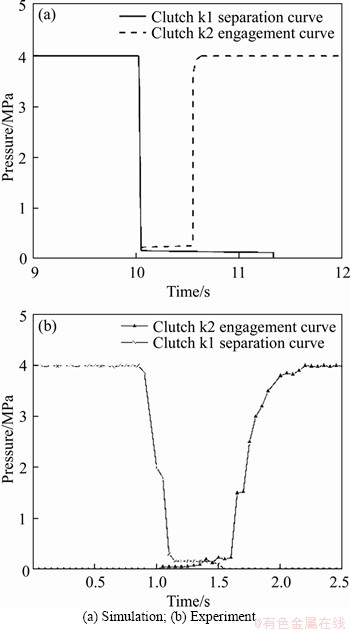
Figure 8 Validation results for clutch shift oil pressure:
It can be seen from Figure 9 that under the oil pressures, the friction torque rapidly increases at 3.2 s when we engage the clutch at 3 s, and then the torque rises to a peak. At the beginning, the piston compresses the spring, and the friction pair does not contact, so there is no torque during 0-0.2 s. Subsequently, the clutch friction pair begins to engage to synchronize, and transfers friction torque by slipping. At the moment when the relative speed of the friction pair drops to zero, the dynamic friction coefficient of the friction pair suddenly changes to the static friction coefficient, and the total torque surges to a peak, which makes the clutch produce a large impact force when working.
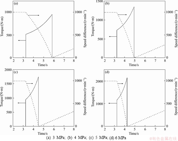
Figure 9 Friction torques and speed differences under different oil pressures:
The speed of the clutch driving part is reduced, the speed of the driven part is increased, and the speed difference is gradually reduced until the engagement is completed to reach 0. After the clutch is disengaged, the speed difference rises and maintains at a certain speed under the action of rotational inertia.
As shown in Figures 10 and 11, the peak value of clutch friction torque increases with the oil pressure, reaching 2146 N・m at 6 MPa, and the minimum torque is 954 N・m at 3 MPa. This is because the greater the oil pressure, the earlier the friction pair enters into the compression stage, and the sharper the contact of the micro-convex body, the greater the friction torque, and the faster the response time of rough friction torque and torque peak.
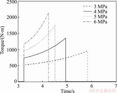
Figure 10 Friction torques under different oil pressures
As the oil pressure increases, the clutch friction time shortens and the engagement speed drops suddenly. In this case, the impact is large, the speed and torque disturbance is significant. This will cause power interruption, which will reduce the tractor’s operating speed and affect the dynamics of the tractor. However, when the oil pressure is small, the engagement time of the friction pair increases, which will result in overheating or excessive wear of the friction discs, and reduce the clutch service life.

Figure 11 Friction peak torques under different oil pressures
5.2 Effect of friction coefficient
The initial speed of the wet clutch is set to 1000 r/min, and the main oil pressure is 4 MPa. The friction coefficients are set to 0.04, 0.08 and 0.12, respectively. The simulation results are shown in Figure 12. The torque under each friction coefficient is integrated, as shown in Figure 13, the solid lines mean the clutch engagement torque, the dashed lines mean speed difference between the driving end and driven end of the clutch.
It can be seen from the figures that under the same oil pressure, the friction coefficient affects the friction torque at the initial engagement process. However, with increasing friction coefficient, the peak friction torque of the wet clutch has not been affected, both of which are 1352 N・m. This is because the slipping friction coefficient suddenly changes to the sticking friction coefficient when the engagement is completed, and the sticking friction coefficient is a certain value.
Due to the influence of the friction surface roughness, the larger the friction coefficient, the shorter the engagement time. If the friction coefficient is too large, it is very likely to cause the friction disc to overheat and cause damage. This clarified that the change in friction coefficient has a greater impact on the clutch friction torque.
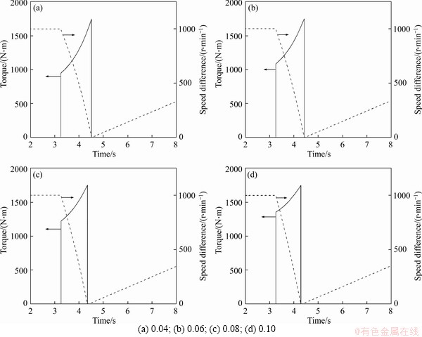
Figure 12 Friction torques and speed differences under different friction coefficients:
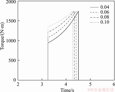
Figure 13 Friction torques under different friction coefficients
6 Simulation of friction power
There is heat generation during the entire engagement process of the wet clutch. In this process, the thermal impulse of frictional heat generated during the clutch slipping is called the friction power, which has a great influence on the thermal performance and service life of the clutch.
The friction power represents the value of the friction work per unit time in per unit size, and reflects the friction heat generation rate and strength during the engagement process [29]. When the friction power absorbed by the friction pair in a unit time is too large, even if the initial engagement speed is small, the friction pair will ablate. It is more accurate to measure the heat and wear of the wet clutch with the friction power, so it is important to study the change regulation.
The differential method is used to calculate the friction power of a pair of friction disc and steel sheet. The simplified model of the friction pair is shown in Figure 14.
The friction force acting on the microcell area is:
FA=μpA=μprφrdr (25)
where μ is coefficient of friction; p is oil pressure; A is friction area of friction pair.
The friction power of friction pair is:
 (26)
(26)

Figure 14 Simplified friction pair model diagram
where r0 is friction disc outer diameter; ri is friction disc inner diameter; μ is coefficient of friction; ω(t) is relative sliding speed of friction pair.
The simulated friction powers of the clutch under different oil pressures and friction coefficients are shown in Figures 15 and 16. As seen, the friction power increases rapidly when the friction pair starts to contact, and reaches the maximum value at 3.2 s. Subsequently, the friction power decreases as the speed difference until it completes the engagement.
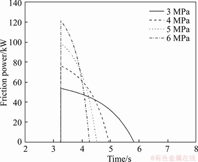
Figure 15 Friction powers under different oil pressures
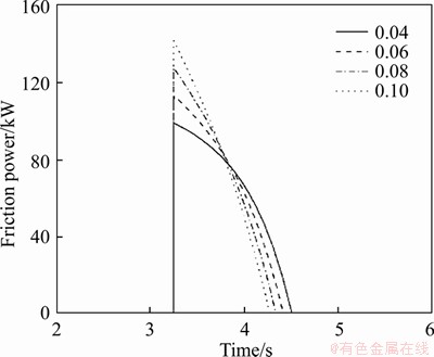
Figure 16 Friction powers under different friction coefficients
In terms of the whole change, the friction power trend is approximately parabolic. This is because the clutch engagement process is complicated. The increase of the friction torque and the reduction of the speed difference are simultaneous, and the interaction between the two affects the friction power.
Like the formation mechanism of clutch friction torque, the clutch engaged at 3 s. However, the reasons for the influence of oil pressure and friction coefficient on the peak friction power are different:
1) The peak friction power increases as the oil pressure increases, and the engagement time decreases as the oil pressure increases. This is because the increased oil pressure shortens the oil film squeezing time, at the same time the surface micro-convex contact area has increased, and various types of torque have also increased, thereby increasing the acceleration of the friction pair speed difference drop, promoting the clutch engagement process and increasing the friction power.
2) The peak friction power increases as the friction coefficient increases, and the engagement time decreases as the friction coefficient increases. This is because the larger the friction coefficient, the rougher the friction pair surface in the full rough contact stage of the clutch engagement characteristic, and the greater the rough contact torque, thereby increasing the acceleration of the friction pair speed difference drop, and advancing the wet clutch engagement process and increasing the friction power.
7 Conclusions
The effect of the oil pressure and dynamic friction coefficient on the shift process of the hydro-mechanical continuously variable transmission is investigated in this paper, and the main conclusions are as follows.
1) Considering the effects of transmission components on the clutch performance, a power train model is built with software of SimulationX. The clutch shift experiment is used to validate the correctness of the model.
2) The friction coefficient function is fitted with the test data to get the friction coefficient model suitable for this paper. It will lay the foundation for the thermal performance optimization of clutch.
3) The large oil pressure and friction coefficient can reduce the slipping time. The large oil pressure can increase the peak torque but the effect of friction coefficient on the peak torque is not so significant. The short engagement time will cause power interruption, which will reduce the tractor’s operating speed and affect the dynamics of the tractor. However, when the engagement time is too long, which will result in overheating or excessive wear of the friction discs, which reduces the clutch service life. Besides, the effect of the oil pressure on the clutch engagement performance is greater than the friction coefficient.
4) The friction power reaches the maximum value at 3.2 s, the peak value increases as the oil pressure and friction coefficient increase. The changes in both oil pressure and friction coefficient have a greater impact on the clutch friction power. The effect of the oil pressure on the clutch thermal performance is greater than the friction coefficient. In order to prevent the clutch from thermal failure, it is necessary to set the oil pressure and friction coefficient within a reasonable range, which will be developed in future research.
Contributors
ZHAO Jing provided the concept and edited the draft of manuscript. XIAO Mao-hua conducted the literature review and wrote the first draft of the manuscript. Petr BARTOS and Andrea BOHATA edited the draft of manuscript.
Conflict of interest
ZHAO Jing, XIAO Mao-hua, BARTOS Petr and BOHATA Andrea declare that they have no conflict of interest.
References
[1] RAIKWAR S, TEWARI V K, MUKHOPADHYAY S, VERMA C R B, RAO M S. Simulation of components of a power shuttle transmission system for an agricultural tractor [J]. Computers and Electronics in Agriculture, 2015, 115: 114-124. DOI: 10.1016/j.compag.2015.03.006.
[2] MASHABI B, AMIRI-RED Y, AFKAR A, MAHMOODI-KALEYBAR M. Simulation of automobile fuel consumption and emissions for various driver’s manual shifting habits [J]. Journal of Central South University, 2014, 21(3): 1058-1066. DOI: 10.1007/s11771-014-2037-x.
[3] SHEN Chu-jing, YUAN Shi-hua, HU Ji-bin, WU Wei, WEI Chao, CHEN Xing. Principle and characteristics of original hydraulic traction drive CVT [J]. Journal of Central South University, 2014, 21(4): 1654-1659. DOI: 10.1007/s11771-014-2107-0.
[4] OMPUSUNGGU A P, PAPY J, VANDENPLAS S P, BRUSSEL H K. A novel monitoring method of wet friction clutches based on the post-lockup torsional vibration signal [J]. Mechanical Systems and Signal Processing, 2013, 35(1, 2): 345-368. DOI: 10.1016/j.ymssp.2012.10.005.
[5] YU Liang, MA Biao, LI Ji-kai, LI Ming-yang. Numerical and experimental studies of a wet multidisc clutch on temperature and stress fields excited by the concentrated load [J]. Triboligy Transactions, 2019, 62(1): 8-21. DOI: 10.1080/10402004. 2018.1453570.
[6] LIU Ji-kai, MA Biao, LI He-yan, CHEN Man, LI Guo-qiang. Control strategy optimization for a dual-clutch transmission downshift with a single slipping clutch during the torque phase [J]. Proceedings of the Institution of Mechanical Engineers, Part D: Journal of Automobile Engineering, 2018, 232(5): 651-666. DOI: 10.1177/0954407017704783.
[7] AL-SHABIBI A M. Transient behavior of initial perturbation in multidisk clutch system [J]. Tribology Transactions, 2014, 57(6): 1164-1171. DOI: 10.1080/10402004.2014.945198.
[8] GREENWOOD J A, WILLIAMSON J B P P. Contact of nominally flat surfaces [J]. Proceedings of the Royal Society of London, 1966, 295(1442): 300-319.
[9] LI M, KHONSARI M M, MCCARTHY D M C, LUNDIN J. On the wear prediction of the paper-based friction materialin a wet clutch [J]. Wear, 2015, 334-335: 56-66. DOI: 10.1016/j.wear.2015.04.005.
[10] KANDA K. Impact of organic sulfur on frictional performance [C]// SAE World Congress Experience. SAE International, 2017: 01487191. DOI: 10.4271/2017-01-1129.
[11] ZHANG Ya-li, ZHANG Xiao-gang, WU Tong-hai, XIE You-bai. Effects of surface texturing on the tribological behavior of piston rings under lubricated conditions [J]. Industrial Lubrication and Tribology, 2016, 68(2): 158-169. DOI: 10.1108/ILT-05-2015-0063.
[12] WEI Wei-hua, LI Yuan-tong, XUE Tong-ming. The research progress of machining mechanisms in milling wood-based materials [J]. Bioresources, 2018, 13(1): 2139-2149. DOI: 10.15376/biores.13.1.Wei.
[13] ZHAO Er-hui, MA Biao, LI He-yan, NAVARRO C. Study on the high temperature friction and wear behaviors of Cu-based friction pairs in wet clutches by pin-on-disc tests [J]. Materials Science & Engineering R-Reports, 2017(4): 4-12. DOI: 10.1155/2017/6373190.
[14] ZHANG Fei-tie, ZHOU Yun-shan, CAI Yuan-chun, XUE Dian-lun. Study on the influence of dynamic friction coefficient of wet clutch on the torque transmission of continuously variable transmission [J]. China Mechanical Engineering, 2013, 24(12): 1682-1686. DOI: http://www. cmemo.org.cn/CN/Y2013/V24/I12/1682. (in Chinese)
[15] FENG Wan-qiang. Research on nonlinear model and characteristics of CVT wet clutch combined process [D]. Changchun: Jilin University, 2008. DOI: https://cdmd.cnki. com.cn/Article/CDMD-10183-2009052630. htm. (in Chinese)
[16] ZHU Hong-qing. Research on the slip characteristics and thermal load characteristics of wet clutch [D]. Hangzhou: Zhejiang University, 2012. DOI: https://cdmd.cnki.com. cn/Article/ CDMD-10335-1012321332.htm. (in Chinese)
[17] LU Xi, WANG Shu-han, LIU Yan-fang, XU Xiang-yang. Application of clutch to clutch gear shift technology for a new automatic transmission [J]. Journal of Central South University, 2012, 19(10): 2788-2796. DOI: 10.1007/s11771-012-1343-4.
[18] SUN Xiao-long, LI Xiao-yan, ZHU You-li, XU Bin-shi. Failure analysis of wear of main clutch separating ring of heavy vehicles [J]. Journal of Central South University of Technology, 2005, 12(2): 124-128. DOI: 10.1007/s11771-005-0023-z.
[19] ZHANG Xin-sheng. Research on the stepless shifting and control strategy of hydraulic mechanical continuously variable transmission [D]. Changchun: Jilin University, 2011. DOI: https://cdmd.cnki.com.cn/Article/CDMD-10183-1011100912. htm. (in Chinese)
[20] XIAO Mao-hua, ZHAO Jing, WANG Yue-wen, ZHANG Hai-jun, LU Zhi-xiong, WEI Wei-hua. Fuel economy of multiple conditions self-adaptive tractors with hydro-mechanical CVT [J]. International Journal of Agricultural and Biological Engineering, 2018, 11(3): 102-109. DOI: 10.25165/j.ijabe. 20181103.2158.
[21] XIAO Mao-hua, WANG Yue-wen, ZOU Fan, ZHANG Hai-jun, LI Xian-hua. Dynamic simulation research of hydre-mechanical CVT [J]. IETE Journal of Research, 2019(4): 1-12. DOI: 10.1080/03772063.2019. 1589391.
[22] XIAO Mao-hua, ZHAO Jing, WANG Yue-wen, YANG Fei, KANG Jing-jing, ZHANG Hai-jun. Research on system identification based on hydraulic pump-motor of HMCVT [J]. Engineering in Agriculture, Environment and Food, 2019, 4(12): 420-426. DOI: 10.1016/ j.eaef.2019.06.004.
[23] IQBAL S, AL-BENDER F, OMPUSUNGGU A P, PLUYMERS B, DESMET W. Modeling and analysis of wet friction clutch engagement dynamics [J]. Mechanical Systems and Signal Processing, 2015, 60-61: 420-436. DOI: 10.1016/j.ymssp.2014.12.024.
[24] HWANG H S, YANG D H, CHOI H K. Torque control of engine clutch to improve the driving quality of hybrid electric vehicles [J]. International Journal of Automotive Technology, 2011, 12(5): 763-768. DOI: 10.1007/s12239-011-0088-7.
[25] NIU Wen-xia, LIU Xiao-qiang, HAN Wen-zheng. Analysis of factors affecting the performance of tracked vehicle friction plates [J]. Ordnance Material Science and Engineering, 2005, 28(3): 30-33. DOI: 10.14024/j.cnki.1004-244x.2005.03.015. (in Chinese)
[26] TUMBUAN T P, NURPRASETIO I P, INDRAWANTO I, ABIDIN Z. Revisiting the Kalman’s conjecture to stabilize the motion of a DC motor in the presence of stribeck friction via PID control [J]. International Review of Automatic Control, 2019, 12(1): 48-58. DOI: 10.15866/ireaco.v12i1.16806.
[27] YANG Li-chen. Simulation analysis of torque characteristics of multi-plate wet clutches [D]. Changchun: Jilin University, 2015. DOI: https://cdmd.cnki.com.cn/Article/CDMD-10183-10155 88092.htm. (in Chinese)
[28] XU Xiao-mei, LIN Ping. Parameter identification of sound absorption model of porous materials based on modified particle swarm optimization algorithm [J]. PloS One, 2021, 16(5): e0250950. DOI: 10.1371/journal.pone.0250950.
[29] GREENFIELD M L, OHTANI H. Friction and normal forces of model friction modifier additives in simulations of boundary lubrication [J]. Molecular Physics, 2019, 117(23, 24): 3871-3883. DOI: 10.1080/00268976.2019.1670876.
(Edited by FANG Jing-hua)
中文导读
基于HMCVT的湿式离合器动态接合特性研究
摘要:本文研究了设计参数对液压机械式无级变速器离合器接合过程的影响。首先,使用SimulationX软件开发了动力传动系的模型,并使用离合器换档实验验证了模型的正确性。然后,将摩擦系数函数与测试数据进行拟合,得出适用于本文的摩擦系数模型。最后,基于摩擦力矩和摩擦力的评价指标,对两组设计参数(油压和摩擦系数)进行了仿真,并从理论上解释了变化规律。根据仿真结果,高油压和摩擦系数可以缩短打滑时间。大的油压可以增加峰值扭矩,但是摩擦系数对峰值扭矩的影响不是很大。摩擦力在3.2 s达到最大值,峰值随着油压和摩擦系数的增加而增加。油压对离合器接合和热性能的影响大于摩擦系数。该研究可为离合器的工作可靠性研究提供参考。
关键词:湿式离合器:摩擦热:摩擦力矩:摩擦能
Foundation item: Project(CX(19)3081) supported by the Agricultural Science and Technology Independent Innovation Fund of Jiangsu Province, China; Project (BE2018127) supported by the Key Research and Development Program of Jiangsu Province, China
Received date: 2020-05-19; Accepted date: 2020-10-29
Corresponding author: XIAO Mao-hua, PhD, Professor; E-mail: xiaomaohua@njau.edu.cn; ORCID: https://orcid.org/0000-0001-5213-1035

