Trans. Nonferrous Met. Soc. China 22(2012) s512-s518
Manufacturing of complex high strength components out of high nitrogen steels at industrial level
Hannes NONEDER, Marion MERKLEIN
Chair of Manufacturing Technology, EgerlandstraΒe 13, 91058 Erlangen, Germany
Received 28 August 2012; accepted 25 October 2012
Abstract: High performance components, e.g., fasteners, nowadays are usually made out of cold forged and heat treated steels like steel 1.5525 (20MnB4). To overcome the problems of heat treatment, e.g., low surface quality, new workpiece materials for cold forging should be found to achieve the needlessness of heat treatment after cold forging. One possible material is given by high nitrogen steels like steel 1.3815 (X8CrMnN19-19). Due to the high strain hardening of these materials the process and tool design for an industrial batch process are challenging and should be conducted by FE-simulation. The numerical results show that, high strength tool materials, like PM-steels or cemented carbides, in most cases, are inevitable. Additionally to the selection of suitable tool materials, the tool layout should be developed further to achieve a high loadability of the tools. The FE-models, used for process and tool design, are validated with respect to the materials’ flow and occurring forming force to assure a proper design process. Also the comparison of strength of components made out of steel 1.5525 in quenched and tempered conditions and steel 1.3815 in strain hardened condition is done. The results show that the component made of steel 1.3815 has a significantly higher strength than the component made of steel 1.5525. This shows that by the use of high nitrogen steels a high performance component can be manufactured by cold forging.
Key words: high nitrogen steel; heat treatable steel; cold forging; FE-simulation; Martens hardness
1 Introduction
Triggered by the discussion on carbon dioxide (CO2) emission of vehicles the efforts for light-weight construction are increased by the automotive industry. However, usually the application of mass optimized components leads to high component loads [1]. Hence, these components, e.g., screws, should be made out of high strength materials like heat treatable steels, e.g. steel 1.5525 (20MnB4). Such steels are suitable for cold forging operations, which is advantageous due to the fact that by cold forging high accuracy is achievable and for huge lot sizes it is economically efficient. But after cold forging a following heat treatment of the components should be conducted, which is disadvantageous due to the geometrical distortion and the low surface quality. Additionally, more than ever further demands, e.g., excellent corrosion resistance or high toughness, should be met by the high performance components. Thus, heat treatable steels should be replaced by new high strength materials which fulfill the demands listed before.
A class of steels, which satisfies those requirements, are high nitrogen steels. In these kinds of steels, carbon is nearly completely substituted by nitrogen and the nitrogen content is above 0.5% (mass fraction). The most outstanding properties of these materials are the high work hardening combined with high ductility and excellent corrosion resistance. Steels 1.3815 (X8CrMnN19-19) and 1.4452 (X13CrMnMoN18-14-3) are classical high nitrogen steels. These two steels are usually used for producing retaining rings for steam driven turbo generators. Retaining rings are necessary to keep the generators’ windings at their place when the generator rotates. Usually, generators’ shaft with a diameter of 2 m rotates at 3000 or 3600 min-1 and power frequencies of 50 and 60 Hz. This high mechanical load, combined with the high thermal load occurring at a turbo generator leads to a high load of which the retaining rings’ material should withstand. Because components made out of high nitrogen steels are able to, they represent an interesting alternative to heat treatable steels.
2 Manufacturing of high performance parts out of high nitrogen steels
2.1 Material and investigations
High nitrogen steels are used widely for manufacturing of retaining rings for turbo generators at power plants because of their excellent corrosion and cracking corrosion resistance additionally to the high work hardening.
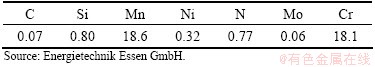
According to Table 1, the austenitic stainless steel 1.3815 shows a nitrogen (N) content of 0.77% (mass fraction) and nearly no carbon (C). Also the contents of manganese (Mn) and chromium (Cr) are on an elevated level. The high chromium content is advantageous with respect to the corrosion resistance and the solubility of nitrogen. A high content of manganese also increases the solubility [2]. On the other hand, a low content of carbon, silicon (Si) and nickel (Ni) is advantageous to the solubility of nitrogen in the melt [3]. Another possibility to increase the solubility of nitrogen is to raise the pressure of the atmosphere during melting of steel and to create a pure nitrogen atmosphere. In the pressure-electro-slag-refining (PESR) process these two demands can be fulfilled. During the melting process an electrode is molten under the layer of slag that is built up of special salts. Due to the higher density the molten material drops through the slag layer and solidifies at the water cooled chill mould, which is made of copper (Cu). During the PESR process the pressure of the nitrogen atmosphere inside the furnace can be increased up to 4.2 MPa. During the melting process the composition of the melt can be adjusted by feeding alloying elements through the locks installed at the furnace. The nitrogen content is adjusted by adding silicon nitride (Si3N4) to the melt [4].
Table 1 Chemical composition of high nitrogen steel 1.3815 (mass fraction, %)
The mechanical properties of the two high nitrogen steels 1.3815 and 1.4452 are characterized in upsetting tests. For these tests the specimens with a diameter of 8 mm and height of 12 mm are used. The test setup is shown in Fig. 1. Here, additionally an optical strain measurement system is shown.
The true strain is calculated by using the deflection corrected stroke of the test machine and the optical strain measurement system ARAMIS. For using this system, a stochastic pattern with high contrast should be applied to the specimen. For example, the needed high contrast can be reached by using a black colour for the pattern on a white grounding. The two different evaluation methods show no significant differences in the results. However, the stroke based evaluation shows slightly higher values of about 25 MPa for the true stress s at 0.6≤ε≤0.8. The resulting true stress―true strain curve is important for FE-based tool design because this curve is one of the most important input data. For the FE-simulations the stroke based evaluated curves are used. Hence, the tool loads calculated tend to be overestimated. This is advantageous because the tool will be designed for more load than really occurring.
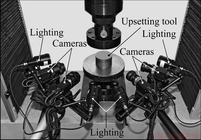
Fig. 1 Test setup of upsetting tests for determining true strain―true stress curves of high nitrogen steels
The upsetting tests are carried out at room temperature because cold forging is in the focus of the work. In order to avoid an improper temperature rise of the specimen and due to the fact that within cold forging the true strain is independent of the forming velocity, the experiment velocity is set to 5 mm/min. Otherwise, an excessive rise of the temperature will lead to an incorrect determination of the true stress―true strain curve. The results of the upsetting tests are shown in Fig. 2. It can be seen from Fig. 2 that at a true strain of ε≈0.75 a difference of stress Δσ≈204 MPa between steels 1.3815 and 1.4452 occurs. The initial yield stress is about 600 MPa for steel 1.3815 and about 701 MPa for steel 1.4452. In contrast, the heat treatable steel 1.5525 (20MnB4) shows an initial yield stress of about 407 MPa and a true stress of σ≈755 MPa at a true strain of ε≈0.8 [5]. For both steels the standard deviation S of the tests is on a very low level. Compared with steel 1.3815 the difference in stress value Δσ is about 1345 MPa at ε≈0.75. This shows the high potential of high nitrogen steels for manufacturing high performance parts by cold forging.
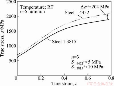
Fig. 2 True stress―true strain curves of high nitrogen steels 1.3815 and 1.4452 determined in upsetting tests
2.2 Industrial batch process as reference process for cold forging of high nitrogen steels
The feasibility of cold forging of high nitrogen steels for producing high performance components is shown at a five-stage industrial batch process. With this process a semi-finished product for fastener for automotive industry can be produced. At the moment for the process the heat treatable steel 1.5525 is used. This material will be substituted by the high nitrogen steel 1.3815 to overcome the problem of heat treatment of steel 1.5525. Within the industrial batch process three different forming procedures, i.e., extrusion, upsetting and shear cutting, occur. The extrusion and upsetting procedures are in the focus of research. The sequence of manufacturing is shown in Fig. 3. At stage 0 the billet is cut from the wire. At stages 1 and 2, an axisymmetrically full forward extrusion process is performed. The tool layout for both stages can be done with a medium amount of time at a two-dimensional, axially symmetric FE-simulation [6]. The tools for stages 1 and 2 are prestressed by three rings and horizontally split to reduce the occurring tool loads. In stage 3 a pre-distribution of material is conducted in a three-dimensional full forward extrusion process. This should be done to have enough material for head upsetting in stage 4. The tool at stage 3 is prestressed by two rings. Like classical upsetting processes, the maximum force occurs at the end of processes. Thus, the highest tool loads occur at this time. Due to the fact that high tool loads occur a special tool layout should be developed to withstand the high loads. This tool layout will be discussed in detail in the following chapter. At stage 5 the head of screws is cut by shearing. After this a thread is rolled at the shaft of components to finish the fastener.
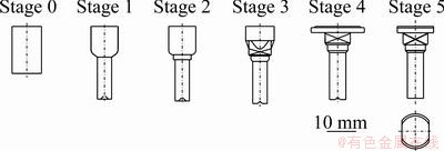
Fig. 3 Sequence of manufacturing sketch of component manufactured out of steels 1.5525 and 1.3815
2.3 Tool layout and optimization for stage 4
The tool layout for stage 4 is in the focus because of the challenging upsetting operation. There are two reasons why this upsetting process is ambitious: first, the material that should be upset is already strain hardened in previous forming stages and second, a non-axisymmetric square should form.
The tools for stage 4 are designed by FE-based results. The FE-simulations are conducted in Simufact Forming 9.0 by setting up a three-dimensional mechanically coupled FE-model which uses hexahedral elements. The FE-model of the initial tool layout is shown in Fig. 4(a). All pictured elements are modelled as deformable bodies. For a first attempt, the tools’ die is horizontally split into upper and lower die to reduce the risk of air and lubricant congestion inside the die, which can lead to insufficient forming of the component and cause serious tool failure within few strokes.
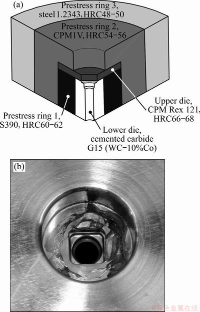
Fig. 4 Initial tool design for forming operation at stage 4 (a) and picture of damaged upper die inside prestress ring 2 at stage 4 after forming of high nitrogen steel 1.3815 (b)
The upper die, which forms the square of the part, is axially prestressed to minimize the bending load occurring during the forming process and ejection of the component. For this, the medium prestress ring is furnished with a nose to enable an axial prestressing. To minimize loads at the corner of the nose a radius with 3 mm is applied. The upper die is prestressed by prestress rings 2 and 3. The shrink fit of the upper die and prestress ring 2 is 0.5%. This is the maximum possible shrink fit. Increasing the shrink fit further can lead to a destruction of the upper die during assembling. Due to the unfavourable aspect ratio of height to diameter and the inevitable bending load, the use of cemented carbide is not recommendable because of its low fracture toughness. Instead, high strength powder metallurgical steel, CPM Rex 121, with a hardness of 66-68HRC is used because this material shows higher toughness than cemented carbides with the same loadability.
The lower part of the die is made out of the cemented carbide G15 (WC-10%Co) in order to withstand the enormous tool loads occurring during the forming process. Here, axial stress up to 5 GPa occurs. In combination with the upper die, the axial prestress is implemented. Hence, the high loads under the lower die a pressure piece also made out of cemented carbide should be used because the loadability of tool steels is not sufficient. Here, a cemented carbide G45 (WC-22.5%Co) is used. The pressure piece is conically shaped to enlarge the cross section in order to reduce the load acting on the cross section. This should be done because the screw used for axial prestressing should be made out of tool steel to achieve the necessary toughness. For this screw the tool steel 1.2379 (X153CrMoV12) with hardness of 58-60HRC is used.
To avoid the fatigue of the cemented carbide caused by positive strain, the die is prestressed by three rings. The material for the inner and medium prestress ring is highly loaded and also a high stress hysteresis occurs. Thus, a tool material is needed, which can achieve high strength and high hardness and shows a low addition to the fatigue. One possible tool material meeting these two main demands are powder metallurgically manufactured (PM) tool steels. As shown in Fig. 4(a), the inner prestress ring is made of the PM high speed steel S390 with a hardness of HRC60-62 to withstand a von Mises stress of about 2.4 GPa. The inner diameter of this ring is 18 mm. Due to the high shrink fit of 0.8% to the die a conical slit instead of a cylindrical one is chosen. This enables an easier assembling and disassembling. The high hardness of HRC62 assures that the material withstands the high loads occurring during the forming process. Because the die should be replaced, e.g., the end of die life reaches, the inner side of the prestress ring is nitrided to enhance the surface hardness. Hence, the wear at the inner side and with it the loss prestress is minimized and the prestress ring can be used for a longer period of time. This is advantageous with regard to tool costs.
The medium prestress ring is made out of the PM hot working steel CPM1V with a hardness of HRC54-56 because this material meets the demands described above and is able to bear a von Mises stress of 2.0 GPa. Hot working steels are used because these materials usually show a higher toughness than cold working or high speed steels. The inner diameter is 40 mm. The shrink fit with respect to the inner prestress ring is 0.5%. Just like at the inner prestress ring, a conical slit is applied for the easier assembling and disassembling and the reduction of wear. Analogue to the inner prestress ring, the inner side of this ring is also nitrided.
The outer prestress ring is also made out of hot working steel, but a conventional one is used because here the load is on a lower level and a more cost-effective material can be used. Hence, the von Mises stress on the inner side of the outer prestress ring is about 1.6 GPa; the hardness is set to HRC48-50 in order to achieve a sufficient toughness to avoid cracks. For minimizing wear during the maintenance, the inner side is nitrided just like the two other rings. The inner diameter of this ring is 70 mm, and the outer diameter is 100 mm. These values are given by the pressing machine used for the industrial batch process. This must not be exceeded because otherwise the tool does not fit into the anvil of the machine. The shrink fit with respect to the medium ring is 0.4%. Here, a conical slit is also applied.
However, the bending load and the pressure caused by upsetting cause the fracture of the tool within 50 strokes at the upper die. This fracture is triggered by overload and is circularly shaped, compared with Fig. 4(b), and has a direct impact on the components quality. Also the low tool life time is disadvantageous with respect to the manufacturing costs and high performance parts out of high nitrogen steels. In order to avoid the drawback of component quality and manufacturing costs the tool design should be developed and optimized. The main goal of the optimization is to find a new design that enables the substitution of the die made out of the high strength steel CPM Rex 121. One possibility to meet this demand is the integration of the upper die into the lower die. For this solution the die is made completely as one piece. Hence, the die can be made out of the cemented carbide G10 (WC-6.5%Co) because no longer bending loads occur in the die. Using this high strength material with high hardness also a high wear resistance can be reached. Axial prestressing is also no longer necessary. A sketch of the improved tool design is shown in Fig. 5.
It can be seen from Fig. 5 that the number of prestress rings is reduced to two. This is advantageous with respect to the tools’ costs. The shrink fit between the die and the inner ring, made out of the PM hot working steel CPM1V, is set to 0.6%. The inner diameter of the ring is 20 mm. Like the original tool layout, the inner side of the prestress ring is nitrided to reduce the wear during assembling or disassembling. The outer prestress is made out of the conventional hot working steel 1.2343 with a hardness of HRC48-50. The inner side of this ring is also nitrided. The inner diameter of the outer prestress ring is 50 mm, and the outer diameter is 100 mm with respect to the prestress used for the industrial batch process. The shrink fit between the inner and outer prestress rings is 0.5%. The slit is implemented in the conical shape in order to reduce the wear during assembling or disassembling.
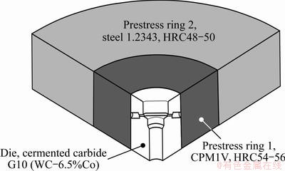
Fig. 5 Improved tool design for forming operation at stage 4
The problem of air and lubricant congestion can be solved by adding venting bores to the die. The best position for these bores should be identified by FE-simulation because these bores should be in a more low loaded area of the tool. The position of the bores can be seen in Fig. 5. At this position the axial as well as the tangential strain is on a low level. The bores also should be at a position where no significant material flow occurs because otherwise the work piece material will flow into the bores and plug them. In this case the corners of the tool only towards the process end are filled with the material. Also the bores should have a diameter as small as possible to reduce the reduction of cross section of the die and with its loadability.
By using such a modified die, the tool life time raises from less than 50 strokes to 250 strokes. Even at 250 strokes no cracks caused by overload or fatigue are detectable. Also the wear is on a negligible level. Due to the fact that the die is removed from the press for investigation, it can be assumed that the tool life will be much higher than 250 strokes. If higher stroke number problems with wear occur the use of suitable CVD coating, e.g., Titan-carbide (TiC) is indicated.
2.4 Validation of FE-models for tool design
The validation of the model can be done by physical validation, e.g., comparing the Martens hardness of the manufactured component with the distribution of local strain, calculated by FE-simulation. The comparison of these two values can be seen as an indicator for material flow. Another possibility of validation is to compare the occurring forming forces with the forming forces obtained by FE-simulation [7].
Hence, at the press, SACMA SP460, used for industrial batch experiments, a piezo-electric load cell, is installed and calibrated for measuring the occurring forming forces. For the validation of the FE-model the maximum occurring force during the process is used. Due to the fact that at stage 4 mainly upsetting is performed the maximum force can be used, because at an upsetting process the maximum tool load occurs at the end of the process and also the maximum force occurs [8]. For having a reliable value the mean value out of 160 strokes is used for the calculation of the maximum force Fmax. The resulting value for Fmax is about 633 kN at a standard deviation of 10.4 kN. On the other hand, the FE-simulation states a maximum force of approximately 591 kN. Thus, a difference of about 42 kN is obtained, which corresponds to about 6.6%. For a proper tool design this can be seen as a sufficient correlation.
As mentioned above, additionally the material flow can be validated. Therefore, Martens hardness tests are carried out on a Fischerscope HM2000 XYp. The tests are conducted according to DIN EN ISO 14577-1. The test load is set to 1 N which is applied and reduced in 20 s. The results of the Martens hardness tests and the FE-simulations are shown in Fig. 6. Here the change of Martens hardness ΔHm in MPa is chosen in order to do a valid comparison with the true strain ε. For the comparison of the results, 3 characteristic zones are considered. For zone 1, a good correlation between the numerical and experimental results is given because equivalent plastic strain ε and also the change of Martens hardness ΔHM are on an elevated level. This is important for a proper prediction of the necessary forming force and the occurring tool loads because here high strain hardened material should form. For zones 2 and 3 the differences occur. In case of zone 2, the simulation shows that slightly higher values for the equivalent plastic strain ε than values of Martens hardness can be measured. Hence, the simulation tends to overestimate the strain hardening of the component in the forming process. As a result, the necessary forming force and with it the occurring tool loads, calculated by the FE-software, are also overrated by 5%-10%. Thus, during the tool design process a higher loadable tool is designed than necessary. In most cases this can be assumed to be beneficial with respect to the tool life. This slight difference can be neglected. Just like zones 2 and 3 differences between numerical and experimental results occur. Here significant deviations can be detected. These are caused due to the fact that for the FE-model, used for process and tool design, the ejection process is not modelled. Also the ejection process has no major impact on the strain of component for the following stages. Hence, this deviation between numerical and experimental data can be disregarded. For the shaft of the component a good correlation can be seen. The true strain ε as well as the change of Martens hardness is on a high level on the outer side of the shaft, decreasing towards the centre. Altogether it can be summarized that the correlation of numerical and experimental results is sufficient with respect to the material flow for the process and tool design.
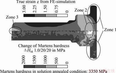
Fig. 6 Comparison of Martens hardness with distribution of equivalent plastic strain for component made out of high nitrogen steel 1.3815
2.5 Comparison of component strength
The component strength is decisive for the possible area of the application. To analyze the component strength, different tests, e.g., tensile test, Martens hardness test, etc. can be performed. But for some applications, for example, if some areas of the part are more loaded than other, it is also important to know where the most loadable areas of the component are localized. In order to get knowledge not only of the strength but also about high loadable areas of the manufactured components, Martens hardness tests should be conducted. Hence, these tests are carried out for components made out of steel 1.3815 in cold forged and steel 1.5525 in quenched and tempered conditions. The screw blank, which is shown in the lower half of Fig. 3 and made out of steel 1.5525, is quenched and tempered to meet the requirement of a screw with a property class of 8.8. To get a closer look to the mechanical properties of the manufactured components Martens hardness is measured. In Fig. 7 it can be seen that due to the quenching and tempering the distribution of Martens hardness is quite homogenous in the screw blank made out of steel 1.5525. Only slight deviations from main strength of 1200 to 1400 MPa occur. Hence, they can be neglected for further considerations. In contrast, the Martens hardness distribution in the component made out of steel 1.3815 is only conditioned by the forming procedure. The comparison of the Martens hardness shows that in every area of the component the values are on a higher level than in the other component made out of steel 1.5525 and quenched and tempered to meet the requirements of a 8.8 screw. According to EN ISO 898-1 the tensile strength should be at least 800 MPa and the elastic limit 640 MPa. The Martens hardness Hm should be in the range between 250 and 320 MPa [9]. Partially the Martens hardness of the component made out of high nitrogen steel is nearly as twice as high. This implicates that the strength of component made out of steel 1.3815 is nearly as twice as high as necessary. This shows that using high nitrogen steels cold forging without heat treatment is sufficient to reach property class of 8.8 and exceed it. Additionally, the component made out of high nitrogen steel shows an excellent corrosion resistance that is advantageous with respect to possible areas of application.
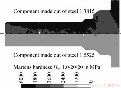
Fig. 7 Comparison of Martens hardness for component made out of steels 1.3815 and 1.5525 in quenched and tempered conditions
3 Conclusion and outlook
The true stress σ of high nitrogen steel 1.3815 is about 1885 MPa at a true strain of ε=0.78. Hence, high forming forces occur, which result in high tool loads. As a result, the tool system should be made out of high strength tool materials. For the die cemented carbides, prestress rings PM steels are suitable. For the inner ring a PM high speed steel is used for the medium ring PM hot working steel. Additionally, the tool layout should be adapted in order to minimize the tool loads. Hence, the high tool loads FE-based process and tool layout step are recommended. In this work, the maximum forming force and the material flow of the FE-model are validated. It is shown that for both output quantities a good correlation is given. Furthermore, a component made out of steel 1.3815 in cold forged condition shows a significantly higher strength than a part made out of steel 1.5525 in quenched and tempered condition. Thus, it can be concluded that high nitrogen steels are suitable for manufacturing high components out of it by cold forging.
Nevertheless more investigations should be done in future. Especially experiments on the toughness of cold forged components made out of high nitrogen steels should be conducted. The main goal of this investigation should be the toughness comparison of the proposed process with that of conventional high performance components. Furthermore, investigations on the wear behavior of cold forged components made out of high nitrogen should be conducted because high performance parts are subject to wear. Hence, a comparison of wear behavior of high nitrogen components and common high performance should be done.
Acknowledgments
The authors gratefully thank the German Federal Ministry of Education and Research (BMBF) for supporting the research project “Hochleistungsbauteile durch Kaltmassivumformung hochfester, druck aufgestickter  (KumDruS)/Cold forging of high performance components composed of high-strength, nitrogen-alloyed steels”. The results were achieved in line with research project within the framework program “
 die Produktion von morgen”. The authors also thank go to
  Karlsruhe (PTKA) for attending.
References
[1]  H, DIETERLE H, HARTMANN G. High strength fasteners [J]. Engineering, 2010(1-2): 18-21.
[2] WU W, DAHL W, JANKE D. Research project of the european unions for coal and steel [M]. 1992.
[3] NIEDERSTRASSER J. Nitrogen content evaluation at low alloyed steels using spark emission spectrometry with respect to singe spark emission spectroscopy [M]. Duisburg, 2002.
[4] STEIN G, MENZEL J,  H. Industrial manufacturing of massively nitrogen alloyed steels [C]// Proceedings of the 1st International Conference on High Nitrogen Steels HNS 88. 1988.
[5] MERKLEINM, NONEDERJ, ENGELU. Methods for measuring true strain―true stress curves of high nitrogen steels [C]// Proceedings of the Conference on Materials Testing. 2010.
[6] NONEDER J, ENGEL U, MERKLEIN M. Tool design for cold forging of high nitrogen steels [C]// Proceeding of the International Cold Forging Congress. Neu Ulm, 2011.
[7] TEKKAYA A E. A guide for validation of FE-Simulations in bulk metal forming [J]. The Arabian Journal for Science and Engineering, 2005, 30: 113-136.
[8] LANGE K. Handbook of metal forming [M]. New York: McGraw-Hill Book Company, 1985.
[9] NN. EN ISO 898-1:2009: Mechanical properties of fasteners made of carbon steel and alloy steel―Part 1: Bolts, screws and studs with specified property classes―Coarse thread and fine pitch thread. 2009.
(Edited by CHEN Wei-ping)
Corresponding author: Hannes NONEDER; E-mail: h.noneder@lft.uni-erlangen.de
DOI: 10.1016/S1003-6326(12)61754-3

