金属型材的多点柔性往复弯曲矫直工艺
来源期刊:中国有色金属学报(英文版)2021年第7期
论文作者:黄学颖 赵军 于高潮 孟庆党 穆振凯 刘彦军
文章页码:2039 - 2050
关键词:多点柔性;金属型材;往复弯曲;统一曲率;过弯矫直;直线度
Key words:multi-point flexibility; metal profile; reciprocating bending; curvature unification; over-bending straightening; straightness
摘 要:提出一种以往复弯曲为特征的多点柔性矫直工艺。从理论上阐述该工艺的变形机理,通过数值模拟和物理实验验证不同材料、不同截面形状的一系列金属型材的矫直。进一步讨论弯曲半径与统一曲率所需往复弯曲次数的关系,并分析矫直型材后残余应力的分布情况。结果表明:往复弯曲过程可以消除初始曲率的差异,使各截面的曲率趋于均匀;型材的弯曲半径越小,达到均匀曲率所需的弯曲次数越少。实验和仿真结果表明,矫直后型材的直线度小于0.2%,验证了该方法的可行性。
Abstract: A multi-point flexible straightening process characterized by reciprocating bending is proposed. Specifically, the process is analyzed in terms of deformation mechanism and verified by numerical simulations and physical experiments of the straightening of a series of metal profiles with different materials and initial shapes. Further, the relationship between the bending radius and the times of reciprocating bending required to unify the curvature is discussed, and the distribution of residual stress after straightening is analyzed. The results show that the reciprocating bending process can eliminate the difference of the initial curvature, make the curvature of each section tend to be uniform; the times of reciprocating bending to reach the uniform curvature decreases with the decrease of bending radius. The straightness of the straightened profile obtained from the experiment and simulation is less than 0.2%, demonstrating a good feasibility of this method.
Trans. Nonferrous Met. Soc. China 31(2021) 2039-2050
Xue-ying HUANG1,2, Jun ZHAO1,2, Gao-chao YU1,2, Qing-dang MENG1,2, Zhen-kai MU1,2, Yan-jun LIU1,2
1. Key Laboratory of Advanced Forging & Stamping Technology and Science, Ministry of Education, Yanshan University, Qinhuangdao 066004, China;
2. College of Mechanical Engineering, Yanshan University, Qinhuangdao 066004, China
Received 12 August 2020; accepted 28 March 2021
Abstract: A multi-point flexible straightening process characterized by reciprocating bending is proposed. Specifically, the process is analyzed in terms of deformation mechanism and verified by numerical simulations and physical experiments of the straightening of a series of metal profiles with different materials and initial shapes. Further, the relationship between the bending radius and the times of reciprocating bending required to unify the curvature is discussed, and the distribution of residual stress after straightening is analyzed. The results show that the reciprocating bending process can eliminate the difference of the initial curvature, make the curvature of each section tend to be uniform; the times of reciprocating bending to reach the uniform curvature decreases with the decrease of bending radius. The straightness of the straightened profile obtained from the experiment and simulation is less than 0.2%, demonstrating a good feasibility of this method.
Key words: multi-point flexibility; metal profile; reciprocating bending; curvature unification; over-bending straightening; straightness
1 Introduction
Most researchers on straightening process focus on metal profiles with a particular specification and material. According to the structural characteristics of straightening machine, LI et al [1] established a mathematical model to analyze the deformation of aluminum profiles. WANG et al [2] analyzed the straightening mechanism for H-section steel and carried out a dynamic simulation, which provided an important theoretical basis for the straightening process optimization of H-section steel. WEISS et al [3] determined the distribution of residual stress by the finite element analysis for aluminum alloy AA6063. GUAN et al [4] established a mechanical model to analyze the bending deformation of profiles in the roller leveling process. Based on the multi-roller straightening analytical model, YIN [5] established a multi-objective optimization model for H-section steel. GUAN et al [6] investigated the mechanical stress-inheriting behavior of strip metal in the roller straightening process. BOUFFIOUX et al [7] studied the effect of the kinematic hardening for the long-rolled profiles by numerical simulation method. ZHAO et al [8,9] established a multi-roller straightening model to solve the relationship between the reduction and residual curvature. Traditional straightening methods often lead to unevenly distributed residual stress, and are only effective to metal profiles of a particular material and shape. It is an urgent need to develop a new straightening process that is flexible and suitable for the metal profiles with various specifications and materials.
For multi-point flexible forming technology, scholars have done a lot of researches. WANG et al [10], CAI et al [11], and WANG and LI [12] applied the multi-point forming technology to the production of aircraft skin. Through the combination of rolling technology and multi-point forming technology, WANG et al [13] proposed a new three-dimensional surface part forming technology, and proved the feasibility and effectiveness of the technology by numerical simulation and experiments. In order to reveal the effect of ultrasonic vibration on flexible-die deep drawing, CAO et al [14] carried out an ultrasonic vibration on the solid granule medium (SGM) deep drawing for AZ31B magnesium alloy sheet. DONG et al [15] did numerical analysis of the flexible-die forming process with SGM. The results showed that the sheet formability was significantly improved. WANG and YUAN [16] presented a numerical method for the coupled deformation between sheet metal and flexible-die to analyze the flexible-die forming process. LIANG et al [17] carried out the experiment, numerical simulation, and theoretical analysis on the forming performance for the bi-directional trapezoidal sandwich plates in the multi-point forming process. LI et al [18] developed a flexible 3D stretch bending device, which can form large-size complex 3D parts. In order to improve forming accuracy and reduce residual stress, SHEN et al [19] developed a multi-point pressure forming equipment to process complex hull plates. Based on the compensated and modified shapes, ZHANG et al [20] established a finite element model of multi-point forming process. The springback modification algorithm can effectively control the forming precision of bi-axial bending plate with variable curvature. ALAVIZADEH et al [21] developed a re-configurable multi-point flexible hydraulic forming die, which can be used to produce various tubes. NOURMOHAMMADI et al [22] designed a re-configurable multi-point die, and then produced parts with hemispheres and free-form surfaces. SONG et al [23] studied the flexible forming with plasma arc, which was a novel thermal stress forming technology with no die and no external force. NIKNEJAD and KARAMI FATH [24] utilized the multi-point forming technology and selected 12 rigid punches of different sizes in the experiment to extrude the round metal billet into the pre-designed shape.
However, the combination of multi-point forming technology and traditional straightening technology has not yet been investigated. Based on the uniform curvature theorem of reciprocating bending and over-bend straightening theory [25,26], a new flexible straightening technology based on the reciprocating bending is proposed. It can solve the straightening problems of metal profiles with different specifications and materials. It has many advantages such as reducing costs, increasing straightening efficiency, and reducing residual stress. In this work, the deformation mechanism of the process is analyzed. The metal profiles with different materials and initial shapes are studied by numerical simulation and physical experiment. The relationship between the bending radius and the times of reciprocating bending required to unify the curvature is discussed. The distribution of residual stress after straightening is analyzed.
2 Process introduction
The multi-point flexible straightening process by reciprocating bending is shown in Fig. 1. The upper die and lower die are composed of multiple punches. By adjusting the position of each punch, different curvatures can be achieved. The process flow is shown in Fig. 2. There are mainly two steps. In the first step, the profile undergoes the multiple reciprocating bending, and the curvature of profile is unified. In the second step, the profile with uniform curvature is over-bent and straightened.
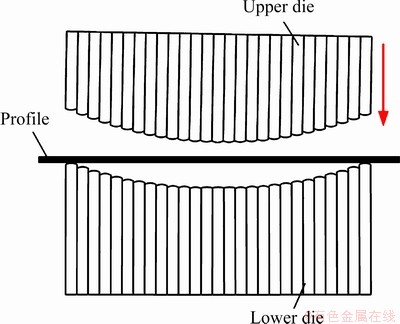
Fig. 1 Schematic diagram of multi-point flexible straightening process
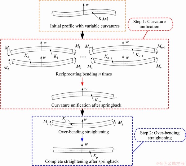
Fig. 2 Process flow of multiple flexible straightening
3 Theoretical analysis
3.1 Curvature unification
The elastic region ratio is introduced to reflect the degree of bending deformation, and it is expressed as
 (1)
(1)
where ξ is elastic region ratio, εt is elastic limit strain, εt=σs/E, σs is yield stress, E is elastic modulus, and εpmax is the maximum strain.
The maximum strain occurs in the outer layer of the section, thus
△Kp=K-K0 (2)
 (3)
(3)
where K is curvature of the profile, K0 is initial curvature of profile, t is thickness of the profile, and △Kp is curvature variation.
Substituting Eqs. (2) and (3) into Eq. (1), ξ can be obtained as
 (4)
(4)
 (5)
(5)
where ws is the distance between the elastic-plastic boundary point and the geometric center layer.
By Eqs. (4) and (5), K can be given as
 (6)
(6)
The bending radius required in simulation and experiments can be determined by Eq. (6). The springback curvature after the nth bending (Kpn) for the rectangular section profile [27] can be expressed by using the mathematical induction as follows:

 (7)
(7)
where D is plastic modulus, σ0 is intercept stress, and Kn is curvature after nth bending.
Here, D/E<<1, when the times of reciprocating bending n is large enough, (D/E)n(K1-K0) and (D/E)n can be ignored, thus the average of Kpn  can be given as follows:

 (8)
(8)
Equation (8) can be expressed simply as
 (9)
(9)
As shown in Eq. (9), the curvature of the profile after the nth reciprocating bending is independent of the initial curvature. In other words, the difference of the initial curvature after multiple reciprocating bending is eliminated.
The derivation process of uniform curvature for H-section or other section profiles is the same as that for rectangular section profile.
3.2 Over-bending straightening
The profile with uniform curvature needs to be straightened by a single over-bending. The bilinear hardening model is adopted in the analysis of over-bending straightening. The relationship between strain (ε) and stress (σ) is as follows:
 (10)
(10)
 (11)
(11)
The loading moment for the rectangular section profile (MR) is calculated as

 (12)
(12)
where z is coordinate axis in the direction thickness of height, A is sectional area; B is width, KpnR is uniform curvature for rectangular section profile, and Kp is the springback curvature, Kp=0.
The loading moment for the H-section profile MH is expressed as


 (13)
(13)
where H is the height of H-section profile, KpnH is the uniform curvature for H-section profile, t2 is the web thickness of H-section profile, t1 is the flange thickness of H-section profile, and ZE=σs/(E|KpnH-Kp|).
The straightening radius 1/Kj required for over-bending straightening can be obtained by Eqs. (12) and (13) as follows:
 (14)
(14)
where Iu is the moment of inertia, and Mj is the loading moment required for over-bending straightening.
4 Numerical simulation
The finite element model of the multi-point flexible straightening process is established using ABAQUS 6.10, as shown in Fig. 3. The profiles are discretized with an 8-node linear hexagonal incompatible mode element (C3D8I). The upper and lower dies are modeled as discrete rigid bodies. The contact between the die and profile is set as the surface-to-surface contact, where the outer surface of die is master, and the outer surface of profile is slave surface. The sliding type is set as finite sliding. The contact property is set as the penalty function method of tangential property with a coefficient of friction to be 0.1. The profiles with three kinds of materials are used. The geometric dimensions and material properties are shown in Tables 1, 2, and 3.
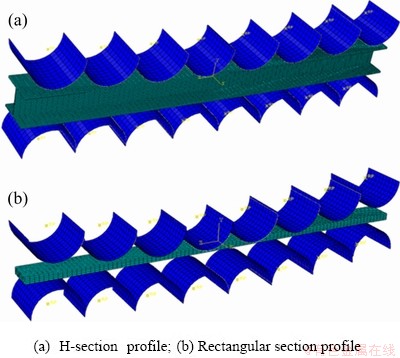
Fig. 3 Finite element models
5 Experimental design
Three kinds of profiles are the same as those in numerical simulation. The experimental setup is shown in Fig. 4. The upper and lower dies are both composed of eight punches. By adjusting the position of the punches, the bending dies with different curvatures can be available. In the experiment, firstly the profile undergoes the multiple reciprocating bending to make the curvature unified, and then the profile with uniform curvature is over-bent and straightened.
6 Results and discussion
6.1 Curvature unification
6.1.1 H-section profiles
The Al6063 H-section profiles with initial curvature radius of 6000 mm are analyzed. The bending radius is set to be 1436 and 1650 mm, respectively. The relationship between the curvature radius and the times of reciprocating bending obtained from simulation and experimental results is shown in Fig. 5 and Fig. 6, respectively.
As shown in Fig. 5 and Fig. 6, the difference of curvature radius decreases with the increase of the times of reciprocating bending under the same bending radius for the single-bend profiles and double-bend profiles. The curvature radius is unified into the same direction and value. The simulation results are the same as experimental results. The above results illustrate the feasibility of uniform curvature process by reciprocating bending for H-section profiles. It can be seen from Fig. 5 that the curvature of the profile is unified after the 8th bending when |1/K|=1436 mm. When |1/K|=1650 mm, the curvature of the profile is unified after the 10th bending. The times of reciprocating bending required for uniform curvature reduces with the decrease of bending radius.
The distribution of equivalent stress for Al6063 H-section profile after uniform curvature is shown in Fig. 7. The equivalent stress of profile tends to be uniform and the residual stress is small. Al6063 H-section profiles after uniform curvature are shown in Fig. 8.
6.1.2 Rectangular section profiles
The rectangular section profiles of 304 and 20# steel with different initial shapes are analyzed.
Table 1 Geometric dimensions of H-section profiles

Table 2 Geometric dimensions of rectangular section profiles
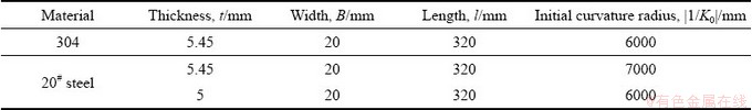
Table 3 Material properties of profiles
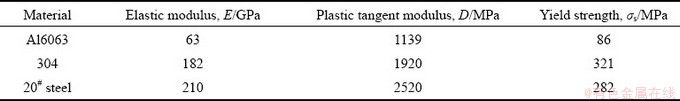
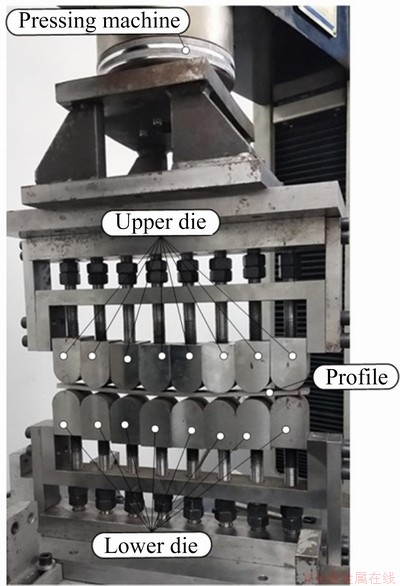
Fig. 4 Experimental setup
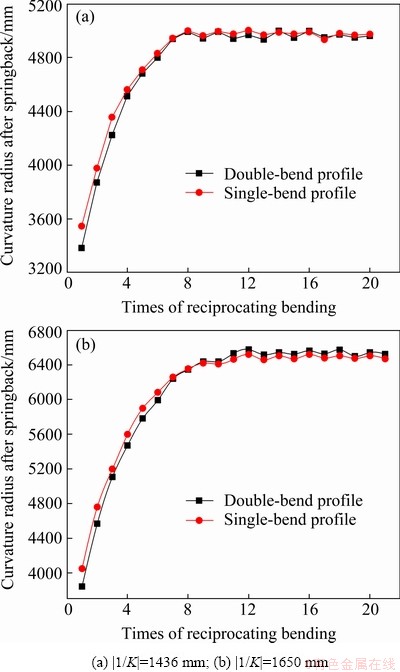
Fig. 5 Relationship between curvature radius and times of reciprocating bending from simulation results for Al6063 H-section profiles at |1/K0|=6000 mm
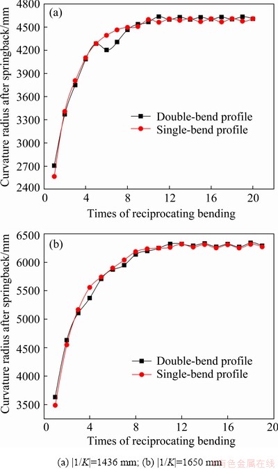
Fig. 6 Relationship between curvature radius and times of reciprocating bending from experimental results for Al6063 H-section profiles at |1/K0|=6000 mm
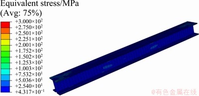
Fig. 7 Distribution of equivalent stress for Al6063 H-section profile after uniform curvature
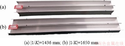
Fig. 8 Al6063 H-section profiles after uniform curvature
The method is the same as that for H-section profiles.
For the rectangular section profiles of 304, when the initial curvature radius is 6000 mm, the bending radius is set to be 1027, 927 and 805 mm, respectively, when the initial curvature radius is 7000 mm, the bending radius is set to be 939 and 821 mm, respectively. The relationship between the curvature radius and the times of reciprocating bending obtained from simulation results and experimental results is shown in Fig. 9 and Fig. 10, respectively.
As shown in Fig. 9 and Fig. 10, the difference of curvature radius decreases gradually with the increase of the times of reciprocating bending under the same bending radius for single-bend profiles and double-bend profiles. The curvature tends to be consistent finally. It is proved that the process of uniform curvature by reciprocating bending is feasible for the 304 rectangular section profiles. When the initial curvature radius is 6000 mm, the curvature of profiles with bending radius of 1027, 927 and 805 mm is unified after the 7th, the 5th, and the 3rd bending, respectively. When the initial curvature radius is 7000 mm, the curvature of profiles with bending radius of 939 and 821 mm is unified after the 5th and the 4th bending, respectively. The times of reciprocating bending required for uniform curvature decreases with the reduction of bending radius of profile.
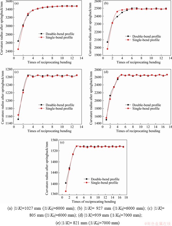
Fig. 9 Relationship between curvature radius and times of reciprocating bending from simulation results for 304 rectangular section profiles
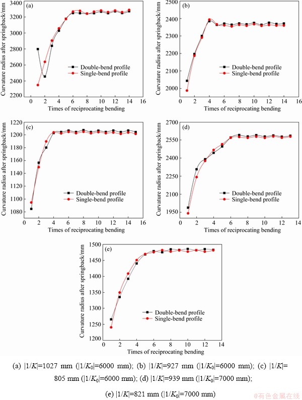
Fig. 10 Relationship between curvature radius and times of reciprocating bending from experimental results for 304 rectangular section profiles
When the initial curvature radius is 6000 mm, the distribution of equivalent stress for 304 rectangular section profile with double-bend is shown in Fig. 11. It can be seen that the equivalent stress of profile tends to be uniform and the residual stress is relatively small. The 304 rectangular section profiles after uniform curvature are shown in Fig. 12.
For the rectangular section profiles of 20# steel, when the initial curvature radius is 6000 mm, the bending radius is set to be 1071 and 942 mm, respectively. The relationship between the curvature radius and the times of reciprocating bending obtained from simulation and experimental results is shown in Fig. 13 and Fig. 14, respectively.
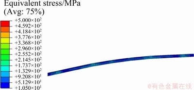
Fig. 11 Distribution of equivalent stress for 304 rectangular section profile after uniform curvature
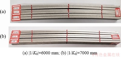
Fig. 12 304 rectangular section profiles after uniform curvature
As shown in Fig. 13, the curvature of profiles with bending radius of 1071 and 942 mm is unified after the 6th and the 5th bending, respectively. It is proved that the times of reciprocating bending required for uniform curvature decreases with the decrease of bending radius. The experimental results are consistent with simulation results. The results show that the uniform curvature principle by reciprocating bending is correct for 20# steel rectangular section profiles.
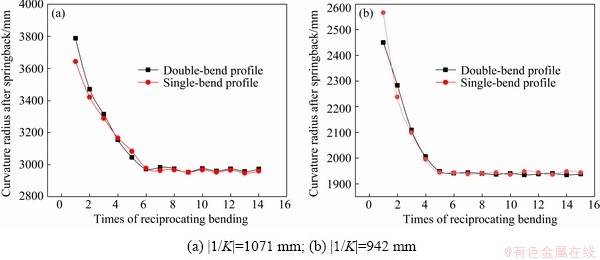
Fig. 13 Relationship between curvature radius and times of reciprocating bending for 20# steel rectangular section profiles from simulation results at |1/K0|=6000 mm
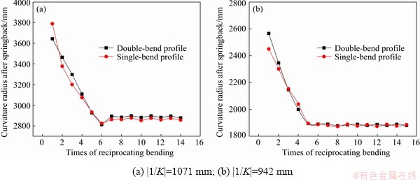
Fig. 14 Relationship between curvature radius and times of reciprocating bending for 20# steel rectangular section profiles from experimental results at |1/K0|=6000 mm
The distribution of equivalent stress for 20# steel rectangular section profile with initial radius of 6000 mm and double-bend is shown in Fig. 15. It can be seen that the equivalent stress of 20# steel rectangular section profile is uniform and the residual stress is small. The 20# steel rectangular section profiles after uniform curvature are shown in Fig. 16.
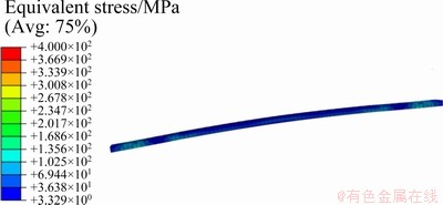
Fig. 15 Distribution of equivalent stress for 20# steel rectangular section profile after uniform curvature
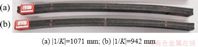
Fig. 16 20# steel rectangular section profiles after uniform curvature
Under the same bending radius condition, the curvature of profiles with same material and different initial shapes is the same after undergoing multiple reciprocating bending. It is proved that the reciprocating bending can eliminate the difference of initial curvature, and finally make the curvature the same value and direction. The times of reciprocating bending required for uniform curvature decreases with the decrease of bending radius. It is verified that the reciprocating bending process is suitable for the profiles with different materials and different specifications.
6.2 Over-bending straightening
According to the above theoretical analysis and the unified curvature, the over-bending straightening is carried out. The maximum residual deflection is obtained from simulation results and experimental results. The straightness of profile is calculated by Eq. (15), and the straightening results are shown in Table 4.
 (15)
(15)
where θ is the straightness of profile, f is the maximum residual deflection of the profile, and l is the length of the profile.
Table 4 Straightness of straightened profiles
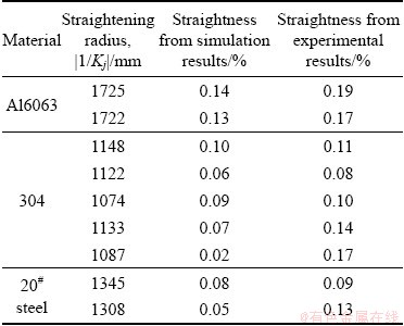
As shown in Table 4, the straightness of straightened profile is less than 0.2%, which meets the requirements of industry. The deviation between experimental results and simulation results is small. It is proved that the multi-point flexible straightening process is feasible.
The equivalent stress distribution of the straightened profiles with different materials and shapes is shown in Fig. 17. It can be seen that the equivalent stress tends to be uniform, and the residual stress is small. The straightening effect of profiles is impressive, and the straightness is within acceptable range. The straightened profiles are shown in Fig. 18.
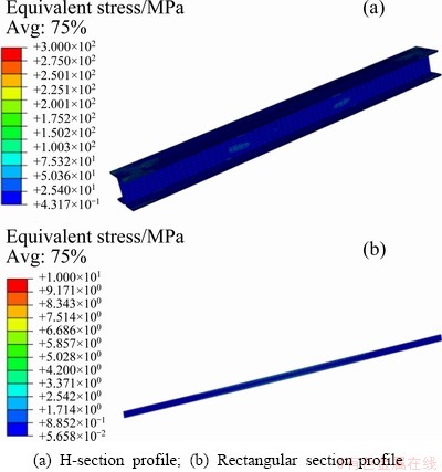
Fig. 17 Equivalent stress distribution of straightened profiles
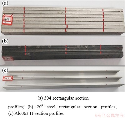
Fig. 18 Straightened profiles
7 Conclusions
(1) Under the same bending radius condition, the curvature of profile with different initial shapes tends to be uniform by multiple reciprocating bending. The reciprocating bending process can eliminate the difference of initial curvature, and finally make the curvature the same value and direction. The times of reciprocating bending required for uniform curvature decreases with the decrease of bending radius.
(2) The straightness of straightened profiles obtained from experiment and simulation is less than 0.2%. The feasibility of multi-point flexible straightening process is verified.
(3) Metal profiles with different materials and specifications are studied by a flexible device. It is proved that the process is flexible and suitable for metal profiles with different materials and specifications.
Acknowledgments
This work was financially supported by the National Natural Science Foundation of China (No. 52005431), the National Natural Science Foundation of Hebei Province, China (No. E2020203086), and the National Major Science and Technology Project of China (No. 2018ZX04007002).
References
[1] LI Ming-ming, HAO Jian-jun, HUANG Qing-xue, LI Jin-feng. Numerical simulation of straightening aluminum profile used for vehicle [J]. Mechanical Engineering & Automation, 2013, 5: 13-14. (in Chinese)
[2] WANG Hui-gang, ZANG Yong, CUI Li-hong, LIU Xue-jiang. Theoretical analyses of bending deflection and FEM simulation of press process on H-BEAM straightening [J]. Machinery Design and Manufacture, 2007, 3: 78-80. (in Chinese)
[3] WEISS M, ROLFE B, HODGSON P D, YANG C H. Effect of residual stress on the bending of aluminium [J]. Journal of Materials Processing Technology, 2012, 212: 877-883.
[4] GUAN Ben, ZANG Yong, WANG Yuan, FENG Sha, LIU Xiao-chan. The influence of process scheme on the straightening effect of section steel [J]. Advanced Materials Research, 2012, 572: 302-307.
[5] YIN Jing. Multi-objective optimisation model of H-beam straightening [J]. Ironmaking & Steelmaking, 2020, 47(2): 124-129.
[6] GUAN Ben, ZANG Yong, WU Di-ping, QIN Qin. Stress-inheriting behavior of H-beam during roller straightening process [J]. Journal of Materials Processing Technology, 2017, 244: 253-272.
[7] BOUFFIOUX C, BOMAN R, CAILLET N, RICH N, PONTHOT J P, HABRAKEN A. Effect of the kinematic hardening in the simulations of the straightening of long rolled profiles [J]. Key Engineering Materials, 2014, 611-612: 178-185.
[8] YIN Jing, ZHAO Jun, WANG Shi-yan, LI Yue-lin, CHEN Min. Establishment of multi-roller straightening reduction rules [J]. Steel Rolling, 2013, 30(4): 19-23. (in Chinese)
[9] ZHAO Jun, SONG Xiao-kang. Control strategy of multi-point bending one-off straightening process for LSAW pipes [J]. The International Journal of Advanced Manufacturing Technology, 2014, 72: 1615-1624.
[10] WANG You, LI Ming-zhe, LIU Hong-wei, XING Jian. Finite element simulation of multi-gripper flexible stretch forming [J]. Procedia Engineering, 2014, 81(10): 2445-2450.
[11] CAI Zhong-yi, WANG Shao-hui, XU Xu-dong, LI Ming-zhe. Numerical simulation for the multi-point stretch forming process of sheet metal [J]. Journal of Materials Processing Technology, 2009, 209: 396-407.
[12] WANG You, LI Ming-zhe. Research on three-dimensional surface parts in multi-gripper flexible stretch forming [J]. The International Journal of Advanced Manufacturing Technology, 2014, 71: 1701-1707.
[13] WANG Da-ming, LI Ming-zhe, CAI Zhong-yi. Continuous- forming method for three-dimensional surface parts combining rolling process with multipoint-forming technology [J]. The International Journal of Advanced Manufacturing Technology, 2014, 72: 201-207.
[14] CAO Miao-yan, LI Jian-chao, YUAN Ya-ning, ZHAO Chang-cai. Flexible die drawing of magnesium alloy sheet by superimposing ultrasonic vibration [J]. Transactions of Nonferrous Metals Society of China, 2017, 27: 163-171.
[15] DONG Guo-jiang, ZHAO Chang-cai, CAO Miao-yan. Flexible-die forming process with solid granule medium on sheet metal [J]. Transactions of Nonferrous Metals Society of China, 2013, 23: 2666-2677.
[16] WANG Zhong-jin, YUAN Bin-xian. Numerical analysis of coupled finite element with element-free Galerkin in sheet flexible-die forming [J]. Transactions of Nonferrous Metals Society of China, 2014, 24: 462-469.
[17] LIANG Xiao-bo, CAI Zhong-yi, ZHANG Xi, GAO Jia-xin. Plastic forming of the doubly curved surfaces of sandwich plates with bi-directionally trapezoidal cores of different sizes [J]. Thin-walled Structures, 2020, 146: 106188.
[18] LI Yi, HAN Xiao, LIANG Ji-cai, TENG Fei, LIANG Ce. Effect of multi-point roller dies on the forming accuracy of profile in flexible 3D stretch bending technology [J]. The International Journal of Advanced Manufacturing Technology, 2021, 112: 897-905.
[19] SHEN Wei, YAN Ren-jun, LIN Yue, LI Pei-yong. Evaluation of residual stress for multi-point repeated forming technology [J]. Ships and Offshore Structures, 2020, 15(8): 815-828.
[20] ZHANG Qing-fang, YUAN Heng-yi, LI Lin-lin, WANG Hong-fen, LIU Song-qing. Springback modification for biaxial bending plate and its validation in multi-point forming [J]. Data Processing Techniques and Applications for Cyber-Physical Systems, 2020, 1088: 249-259.
[21] ALAVIZADEH S M, SHAHBAZI KARAMI J. Experimental and numerical investigation on metal tubes forming with a novel reconfigurable hydroforming die based on multi-point forming [J]. Production Engineering, 2019, 13: 489-500.
[22] NOURMOHAMMADI A A, ELYASI M, MIRNIA M J. Flexibility improvement in two-point incremental forming by implementing multi-point die [J]. The International Journal of Advanced Manufacturing Technology, 2019, 102: 2933-2952.
[23] SONG Wen-qing, XU Wen-ji, WANG Xu-lue, MENG Jian-bing, LI Hong-you. Numerical simulation of temperature field in plasma-arc flexible forming of laminated-composite metal sheets [J]. Transactions of Nonferrous Metals Society of China, 2009, 19(S1): 61-67.
[24] NIKNEJAD A, KARAMI FATH L. Teflon-pad shaping process of circular metal blanks into quasi-cup specimens by theoretical and experimental methods [J]. Transactions of Nonferrous Metals Society of China, 2016, 26: 213-227.
[25] YU Gao-chao, ZHAO Jun, MA Rui, ZHAI Rui-xue. Uniform curvature theorem by reciprocating bending and its experimental verification [J]. Journal of Mechanical Engineering, 2016, 52: 57-63. (in Chinese)
[26] ZHAO Jun, CAO Hong-qiang, ZHAN Pei-pei, MA Rui. Pure bending equivalent principle for over-bend straightening and its experimental verification [J]. Journal of Mechanical Engineering, 2012, 48(8): 28-33. (in Chinese)
[27] ZHAO Jun, YIN Jing, MA Rui, MA Li-xia. Springback equation of small curvature plane bending [J]. Science in China: English Edition of Technical Science, 2011, 54(9): 2386-2396.
黄学颖1,2,赵 军1,2,于高潮1,2,孟庆党1,2,穆振凯1,2,刘彦军1,2
1. 燕山大学 先进锻压成形技术与科学教育部重点实验室,秦皇岛 066004;
2. 燕山大学 机械工程学院,秦皇岛 066004
摘 要:提出一种以往复弯曲为特征的多点柔性矫直工艺。从理论上阐述该工艺的变形机理,通过数值模拟和物理实验验证不同材料、不同截面形状的一系列金属型材的矫直。进一步讨论弯曲半径与统一曲率所需往复弯曲次数的关系,并分析矫直型材后残余应力的分布情况。结果表明:往复弯曲过程可以消除初始曲率的差异,使各截面的曲率趋于均匀;型材的弯曲半径越小,达到均匀曲率所需的弯曲次数越少。实验和仿真结果表明,矫直后型材的直线度小于0.2%,验证了该方法的可行性。
关键词:多点柔性;金属型材;往复弯曲;统一曲率;过弯矫直;直线度
(Edited by Wei-ping CHEN)
Corresponding author: Gao-chao YU, Tel: +86-15133589652, E-mail: gch_yu@ysu.edu.cn
DOI: 10.1016/S1003-6326(21)65636-4
1003-6326/ 2021 The Nonferrous Metals Society of China. Published by Elsevier Ltd & Science Press

