J. Cent. South Univ. (2017) 24: 296-302
DOI: 10.1007/s11171-017-3430-7

Analysis of strain variation in cross shear zone of plate during snake hot rolling
ZHANG Tao(����)1, 2, 3, WU Yun-xin(������)1, 2, 3, GONG Hai(����)1, 2, 3,
SHI Wen-ze(ʯ����)1, 2, 3, JIANG Fang-min(������)1, 2, 3
1. College of Mechanical and Electrical Engineering, Central South University, Changsha 410083, China;
2. State Key Laboratory of High Performance Complex Manufacturing (Central South University),
Changsha 410083, China;
3. Nonferrous Metal Oriented Advanced Structural Materials and Manufacturing Cooperative Innovation Center, Central South University, Changsha 410083, China
 Central South University Press and Springer-Verlag Berlin Heidelberg 2017
Abstract: In order to study the distribution of equivalent and shear strain of aluminum alloy plate during snake hot rolling, several coupled thermo-mechanical finite element models (FEM) are established. Effects of speed ratio and offset distance on strain distribution of the plate are analyzed. The length of cross shear zone is defined to have a better understanding of the deformation characteristic in cross shear zone, which is the essential difference from symmetrical rolling in deformation zone. The results show that the equivalent strain and shear strain of lower part both increase with the increase of speed ratio, while the upper part decreases; the equivalent strain through the whole thickness decreases with ascending offset distance, while the shear strain of lower part increases. The length of cross shear zone quickly increases with ascending speed ratio and slightly decreases with ascending offset distance. The ��positive�� and ��negative�� cross shear zones are formed with the increase of speed ratio and offset distance, respectively. The value of the sensitivity coefficient of speed ratio is an order of magnitude bigger than the offset distance. However, the shear strain at center point increases with the ascending speed ratio and offset distance for different mechanism. As speed ratio increases, the asymmetry of the distribution of equivalent is becoming larger and the shear strain is generated in the same direction in cross shear zone. The FEM results agree well with experimental results.
Key words: aluminum alloy plate; snake hot rolling; speed ratio; offset distance; cross shear zone
1 Introduction
Aluminum alloy with high strength and high toughness, especially for 7055 and 7150 aluminum alloy plates are widely used in the field of aerospace [1]. With the development of manufacture of aircraft, thicker aluminum alloy plates (even to 250 mm) with homogeneous properties are in great need. Hot rolling is critical process of manufacture of aluminum alloy plate. However, products of such thick plates with homogeneous properties through the thickness cannot be processed using the symmetrical rolling equipment. A new technique of snake rolling was studied, which has been first used in 4064 mm hot rolling mill in Germany [2].
Many precious studies have been conducted on the deformation and microstructure in hot rolling process [3�C7]. Even in symmetrical rolling, there is also strain inhomogeneity for thick plate [8]. Researches about asymmetrical rolling were mainly focused on asynchronous rolling for different velocities or radiuses of two work rolls. The effect of speed ratio on distribution of shear stress and shear strain in asynchronous rolling drew the attention of many researchers [9�C11]. LIU et al [12] studied effects of different diameter ratios for two rolls of asymmetrical rolling on microstructure and rolling force. The difference of strain distribution between symmetrical rolling and snake rolling was studied [13]. On the basis of the strain and temperature analysis, coupled models of microstructure were also established [14�C19].
However, few studies have been conducted on the new method of snake rolling, especially effects of rolling parameters on the distribution of shear strain and deformation characteristic in cross shear zone. In this work, on the basis of definition of length of cross shear zone, the effects of speed ratio and offset distance on the length of cross shear zone and shear strain at center of the plate are studied. Meanwhile, the strain distribution in three different zones in deformation zone is presented, especially for the variation in cross shear zone.
2 Numerial models
2.1 Snake rolling
Figure 1 shows the schematic diagram of snake rolling. Snake rolling is achieved by a horizontal offset distance of upper roll in outlet direction, in which the lower work roll has a larger velocity than the upper roll. In Fig. 1 V1 and V2 represent velocities; ��1 and ��2 represent neutral angles; X1 and X2 represent neutral points of upper and lower roll, respectively; S is offset distance; H is initial thickness; h is outlet thickness of the plate. As a result, the deformation zone of the plate is divided into three zones: backward slip zone, cross shear zone and forward slip zone. In cross shear zone, the friction direction in the surface of the plate is opposite and the plate is subjected to large shear strain. Cross shear zone does not appear in symmetrical rolling, which is the distinction in snake rolling compared to symmetrical rolling.
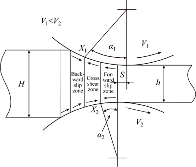
Fig. 1 Schematic diagram of snake rolling
2.2 Models description
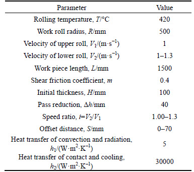
Coupled thermo-mechanical models of snake hot rolling and symmetrical rolling are established. Thermal conductivity is taken into consideration for work rolls. The material of the plate is 7055 aluminum alloy in casting state; its flow stress model is defined in Eq. (1). The rolling parameters are given in Table 1.
 (1)
(1)
where Z is Zener�CHollomon parameter and it represents the effects of the temperature and strain rate on the deformation behavior;  is the strain rate; R is the gas constant (8.31 J/(mol��K)); T is the thermodynamic temperature; �� is the flow stress for a given stain.
The differences between snake rolling and symmetrical rolling are the speed ratio and offset distance and they have different effects on the distribution of the equivalent strain and shear strain.
Table 1 Rolling parameters
2.2.1 Speed ratio
The effect of speed ratio on the distribution of the equivalent strain and shear strain is shown in Fig. 2. The equivalent strain of lower part increases with the increase of speed ratio, while the upper part decreases. The value of the equivalent strain is almost equal at the position of30 mm from upper surface where several curves are intersected in Fig.2(a). The shear strain distribution is similar to that of the equivalent strain. The curves intersected at the position of 40 mm from upper surface indicate that the strain can be quickly penetrated into the center portion. However, the value of the shear strain is 1/3�C1/4 of the equivalent strain. Because the shear strain is mainly generated in the cross shear zone, the length of this zone is quite smaller compared to the deformation zone.
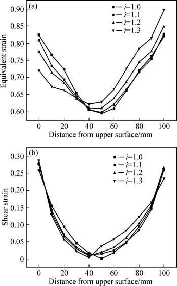
Fig. 2 Effect of speed ratio on distribution of equivalent strain (a) and shear strain (b) under conditions R=500 m, m=0.4, S=0, V1=1 m/s, ��h=40 mm
2.2.2 Offset distance
Figure 3 shows the effect of offset distance on the distribution of the equivalent strain and shear strain. The equivalent strain is decreased with ascending offset distance. The distribution of equivalent strain is almost symmetrical when the offset distance is less than 30 mm. The distribution of equivalent strain is obviously asymmetrical and the strain of the lower portion is larger than the upper portion when the offset distance exceeds 30 mm. It can be easily seen that the equivalent strain is smaller than the symmetrical rolling on the whole thickness. This is because the actual pass reduction is smaller than that of the given reduction with the ascending offset distance. However, the variation of the shear strain is different from the equivalent strain. The shear strain of lower part is increased with the increaseof offset distance, while the upper part decreases. The curves intersected at the position of 40 mm from upper surface are similar to the effects of speed ratio, which indicates that the increase of offset distance has positive effect on the penetration of the deformation from the surface of the plate to its center.
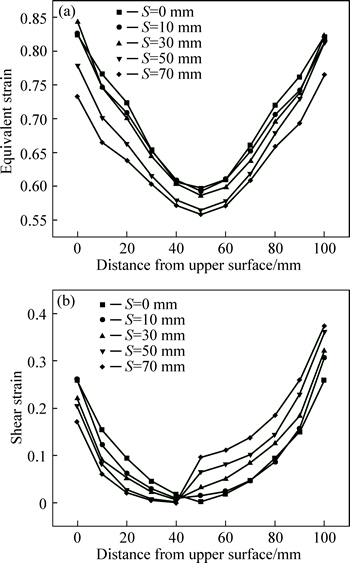
Fig. 3 Effect of offset distance on distribution of equivalent strain (a) and shear strain (b) under conditions R=500 m, m=0.4, i=1, V1=1 m/s, ��h=40 mm
3 Results and discussion
3.1 Variation of length of cross shear zone
From Fig. 1, the obvious difference between snake rolling and symmetrical rolling is the cross shear zone in deformation zone. In this zone, the plate is not only subjected to compressive strain, but also strong shear strain is beneficial to the deformation into the center of the plate. In order to study the effect of the cross shear zone on the variation of shear strain quantitatively, the length of the cross shear zone is defined as follows:
 (2)
(2)
where B is the length of cross shear zone; X1 and X2 are the neutral points of the upper and lower surface, respectively. The direction of the frictions is changed after the neutral point, as shown in Fig. 1.
The variation of the speed ratio and offset distance will change the position of the neutral points and then change the length of cross shear zone. It is concerned that the proportion of the cross shear zone on the whole deformation zone and the length of the whole deformation zone is calculated as follows:
 (3)
(3)
where L is the length of the whole deformation zone; r is the radius of the roll; ��h is the pass reduction.
The results of the effect of speed ratio and offset distance on the length of cross shear zone are shown in Fig. 4. In symmetrical rolling, the length of cross shear zone is zero. It is obvious that the length of cross shear zone quickly increases with the increase of speed ratio and ��positive�� cross shear zone is formed because the lower neutral point is closer to the outlet direction. The length of cross shear zone is decreased with ascending offset distance and ��negative�� cross shear zone is formed because the lower neutral point is closer to the outlet direction with the increase of offset distance for a given speed ratio. Meanwhile, the shape of the surface is similar to a plane; therefore, a linear plane can be fitted to study the sensitivity coefficient of the variation of speed ratio and offset distance on the length of cross shear zone. The results are shown in Fig. 4 and Eq. (4):
 (4)
(4)
where ��V is the velocity difference of two work rolls; is the average velocity of two work rolls.
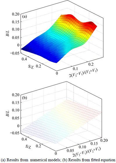
Fig. 4 Variation for length of cross shear zone:
The sensitivity coefficient of the speed ratio is positive and ��positive�� cross shear zone is formed; the sensitivity coefficient of the offset distance is negative and ��negative�� cross shear zone is formed. The value of the sensitivity coefficient of speed ratio is an order of magnitude bigger than the offset distance, which indicates that speed ratio plays a dominant role in the variation of length of cross shear zone. The offset distance is mainly used to decrease the bending curvature of the plate in the snake rolling process [20].
3.2 Variation of shear strain at center point
Snake rolling is used to obtain large deformation and fine grain at the center of thick plate. It is known that large shear strain is beneficial to fine grains. In snake rolling, strong shear strain is mainly generated in cross shear zone; the variation of the length of cross shear zone is related to the change of speed ratio and offset distance. The effects of speed ratio and offset distance on the shear strain at center point of the plate are presented in Fig. 5. The shear strain is increased with the ascending speed ratio and offset distance, which is different from the effect of two factors on the length of cross shear zone.
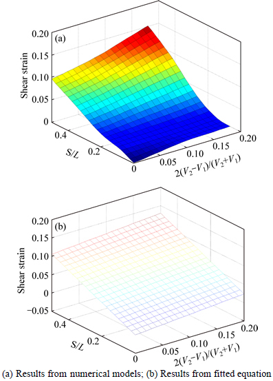
Fig. 5 Variation for shear strain at center point:
The shape of the surface is similar to a plane and a linear plane can be fitted. The results are shown in Fig. 5 and Eq. (5):
 (5)
(5)
where �� is the shear strain at center point of the plate.
The sensitivity coefficient of the speed ratio and offset distance are both positive and the increases of the two factors have positive effect on the increase of shear strain. The sensitivity coefficient of the two factors is in the same order of magnitude and the sensitivity coefficient of offset distance is a little bigger, which indicates that offset distance plays a more important role in the variation of the shear strain. However, the mechanisms of them are different. As speed ratio increases, the length of cross shear zone is increased for a given deformation length; as offset distance increases, the torque formed by the upper and lower rolling forces increases, which is good for the enlargement of the shear strain.
3.3 Variation of strain distribution in different zones
In order to track the variation and the asymmetrical distribution of the equivalent and shear strain in snake rolling, the strain distribution in three different zones is studied. The effect of speed ratio on the equivalent strain is depicted in Fig. 6. The distribution of equivalent strain is almost symmetrical in all zones when speed ratio is less than 1.1. As speed ratio increases, the asymmetry is increased and is serious in the cross shear zone. As a result, when the plate is rolled out of the gap, the strain distribution is asymmetrical in the forward slip zone inherited from the cross shear zone. The commonness in these zones is that the equivalent strain in the lower portion is larger than the upper portion and the gap is increased with ascending speed ratio. Figure 7 shows theeffect of speed ratio on the shear strain. When the speed ratio is 1.1, shear strain distribution is nearly symmetrical in backward and forward slip zone, however, it is asymmetrical in cross shear zone; which is different from the equivalent strain. As speed ratio increases, the values of shear strain through the thickness in the cross shear zone are negative, while there are both positive and negative values when speed ratio is 1.1. Therefore, shear strain is generated in the same direction in cross shear zone when speed ratio exceeds 1.1 and it gives that strong shear strain can be obtained at large speed ratio.
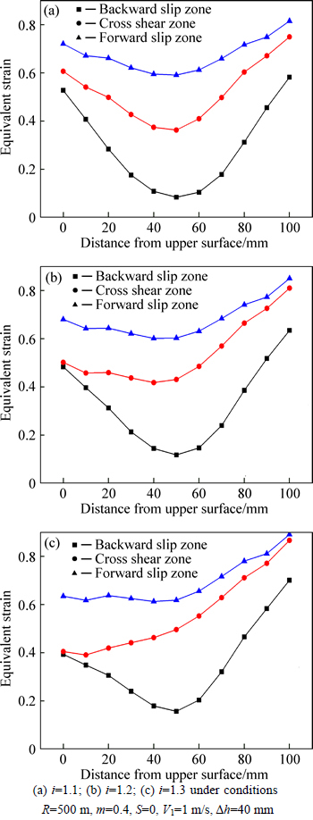
Fig. 6 Effect of speed ratio on equivalent strain distribution in different zones:
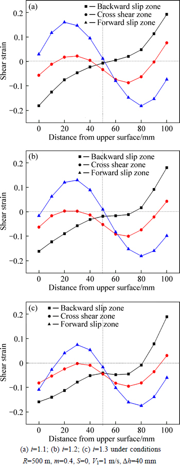
Fig. 7 Effect of speed ratio on shear strain distribution in different zones:
4 Experiments
The experiment was conducted on snake rolling mill remolded by conventional rolling mill. Different velocities can be achieved when two work rolls are driven by two motors. Several spacers with different thicknesses were inserted into both sides between bearing boxes of rolls and the frame. Horizontal offset distance adjustment can be achieved by changing the thickness of spacers. Table 2 gives parameters of experimental snake rolling mill.
Aluminum alloy 7055 with composition (mass fraction,%)Al+8.34Zn+2.21Mg+2.35Cu+0.11Zr +0.05Ti was machined into 150 mm(length)��60mm (width)��20 mm(thickness) and 4 mm��4 mm grid was marked in the surface of the plate. The snake rolling temperature was 410 ��C Experiment schedule is given in Table 3. The speed ratio and offset distance were 1.0 and 0 mm in symmetrical rolling and other parameters were the same as snake rolling. After 3 passes rolling, the plate was heated in the heating furnace at 410 ��C for 1 h.
Table 2 Parameters of experimental snake rolling mill
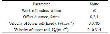
Table 3 Snake rolling experiment schedule
The width of the plate is quite larger than its thickness; therefore, the 3-D rolling can be simplified to a plane strain problem. In the model of plane strain, ez, gyz, gxz are set as zero and the effective strain is calculated by Eq. (6).
 (6)
(6)
where ee is effective strain; ex and ey are normal strains in x and y direction respectively; gxy is shear strain in xy plane.
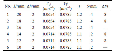
Figure 8 shows the method of calculation of strain and the formulas are given in Eq. (7):
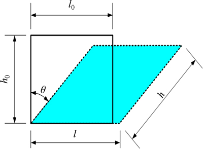
Fig. 8 Schematic of strain calculation
 (7)
(7)
where lo and l are the length of the grid before and after rolling; ho and h are the height of the grid before and after rolling; �� is the angle in the vertical direction before and after rolling.
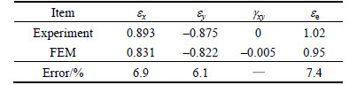
The grids for different rolling ways are presented in Fig. 9 and the strain comparisons of snake rolling and symmetrical rolling are shown in Tables 4 and 5, respectively. The maximum error is 8.6% and the FEM results agree with experimental results.
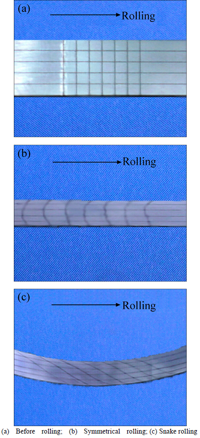
Fig. 9 Grids for different rolling ways (arrow represents rolling direction):
Table 4 Comparisons of strain at center point between FEM and experimental results in snake rolling
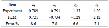
Table 5 Comparisons of strain at center point between FEM and experimental results in symmetrical rolling
5 Conclusions
1) The equivalent strain and shear strain of lower part are increased with ascending speed ratio and the gap also increases between two surfaces. The increase of offset distance has negative effect on equivalent strain through the whole thickness, while the shear strain of lower part increases.
2) A ��positive�� cross shear zone is formed with the increase of speed ratio, while ��negative�� for offset distance. The increases of speed ratio and offset distance are beneficial to the enlargement of shear strain at center point of the plate.
3) The relationship of length of the cross shear zone between speed ratio and offset distance is fitted, which indicates that speed ratio plays a dominant role in the variation of length of cross shear zone. This analysis provides guidance for the calculation of length of cross shear zone in snake hot rolling.
References
[1] LI Xing-dan. Development of commercial aircraft aluminum alloy structural materials [J]. Shanghai Nonferrous Metals, 1994, 15(3): 160�C168. (in Chinese)
[2] YANG Shi-de. Introduction of asymmetric aluminum hot rolling and mill [J]. World Nonferrous Metals, 2010(2): 47. (in Chinese)
[3] LIN Z C, SHEN C C. A rolling process two-dimensional finite element model analysis [J]. Finite Elements in Analysis and Design, 1997, 26(2): 143�C160.
[4] TIMOTHY S P, YIU H L, FINE J M, RICKS R A. Simulation of single pass of hot rolling deformation of aluminium alloy by plane strain compression [J]. Materials Science and Technology, 1991, 7(3): 255�C263.
[5] DUAN X, SHEPPARD T. Three-dimensional thermal mechanical coupled simulation during hot rolling of Aluminium alloy 3003 [J]. International Journal of Mechanical Sciences, 2002, 44(10): 2155�C2172.
[6] YANG H, WANG M, GUO L G, SUN Z C. 3D coupled thermo-mechanical FE modeling of blank size effects on the uniformity of strain and temperature distributions during hot rolling of titanium alloy large rings [J]. Computational Materials Science, 2008, 44(2): 611�C621.
[7] DAVENPORT S B, HIGGINSON R L, SELLARS C M. The effect of strain path on material behaviour during hot rolling of FCC metals [J]. Philosophical Transactions of the Royal Society of London A: Mathematical, Physical and Engineering Sciences, 1999, 357(1756): 1645�C1661.
[8] SERAJZADEH S, TAHERI A K, NEJATI M, IZADI J, FATTAHI M. An investigation on strain inhomogeneity in hot strip rolling process [J]. Journal of Materials Processing Technology, 2002, 128(1): 88�C99.
[9] MOUSAVI S, EBRAHIMI S M, MADOLIAT R. Three dimensional numerical analyses of asymmetric rolling [J]. Journal of Materials Processing Technology, 2007, 187: 725�C729.
[10] ZUO Fang-qing, JIANG Jian-hua, SHAN Ai-dang, FANG Jian-min, ZHANG Xing-yao. Shear deformation and grain refinement in pure Al by asymmetric rolling [J]. Transactions of Nonferrous Metals Society of China, 2008, 18(4): 774�C777.
[11] YUAN Fu-shun, SUN Ji-quan. Deformation analysis in deformation zone of asymmetrical rolling with different roll velocity [J]. Shandong Metallurgy, 2010, 32(6): 25�C27. (in Chinese)
[12] LIU Jie, KAWALLA R. Influence of asymmetric hot rolling on microstructure and rolling force with austenitic steel [J]. Transactions of Nonferrous Metals Society of China, 2012, 22: s504�Cs511.
[13] ZHANG Tao, WU Yun-xin, GONG Hai, ZHENG Xi-zhao, JIANG Shao-song. Effects of rolling parameters of snake hot rolling on strain distribution of aluminum alloy 7075-TNMSC [J]. The Chinese Journal of Nonferrous Metals, 2015, 24(7): 2150-2156.
[14] CHO S H, YOO Y C. Hot rolling simulations of austenitic stainless steel [J]. Journal of Materials Science, 2001, 36(17): 4267�C4272.
[15] SHAHANI A R, SETAYESHI S, NODAMAIE S A, ASADI M A, REZAZE S. Prediction of influence parameters on the hot rolling process using finite element method and neural network [J]. Journal of Materials Processing Technology, 2009, 209(4): 1920�C1935.
[16] LIU Y, LIN J. Modelling of microstructural evolution in multipass hot rolling [J]. Journal of Materials Processing Technology, 2003, 143: 723�C728.
[17] ZHOU S X. An integrated model for hot rolling of steel strips[J]. Journal of Materials Processing Technology, 2003, 134(3): 338�C351.
[18] AHMED H, WELLS M A, MAIJER D M, HOWES B J, WINDEN M R. Modelling of microstructure evolution during hot rolling of AA5083 using an internal state variable approach integrated into an FE model [J]. Materials Science and Engineering A, 2005, 390(1): 278�C290.
[19] DING Han-lin, HIRAI K, HOMMA T, KAMADO S. Numerical simulation for microstructure evolution in AM50 Mg alloy during hot rolling J]. Computational Materials Science, 2010, 47(4): 919�C925.
[20] ZHANG Tao, WU Yun-xin, GONG Hai, ZHENG Xi-zhao, JIANG Shao-song. Bending analysis and control of rolled plate during snake hot rolling [J]. Journal of Central South University, 2015, 22: 2463�C2469.
(Edited by YANG Hua)
Cite this article as: ZHANG Tao, WU Yun-xin, GONG Hai, SHI Wen-ze, JIANG Fang-min. Analysis of strain variation in cross shear zone of plate during snake hot rolling [J]. Journal of Central South University, 2017, 24(2): 296-302. DOI: 10.1007/s11171-017-3430-7.
Foundation item: Project(51405520) supported by the National Natural Science Foundation of China; Project(2012CB619505) supported by National Basic Research Program of China
Received date: 2015-09-23; Accepted date: 2016-03-22
Corresponding author: GONG Hai, Lecturer, PhD; Tel: +86-15874076234; E-mail: gonghai@csu.edu.cn

