
J. Cent. South Univ. (2018) 25: 1708-1716
DOI: https://doi.org/10.1007/s11771-018-3862-0

Heat transfer performance testing of a new type of phase change heat sink for high power light emitting diode
XIANG Jian-hua(��)1, ZHANG Chun-liang(�Ŵ���)1, ZHOU Chao(�ܳ�)1,LIU Gui-yun(������)1, ZHOU Wei(��ΰ)2
1. School of Mechanical and Electric Engineering, Guangzhou University, Guangzhou 510006, China;
2. Department of Mechanical and Electrical Engineering, Xiamen University, Xiamen 361005, China
 Central South University Press and Springer-Verlag GmbH Germany, part of Springer Nature 2018
Abstract: In view of the limitations of solid metal heat sink in the heat dissipation of high power light emitting diode (LED), a kind of miniaturized phase change heat sink is developed for high power LED packaging. First, the fabrication process of miniaturized phase change heat sink is investigated, upon which all parts of the heat sink are fabricated including main-body and end-cover of the heat sink, the formation of three-dimensional boiling structures at the evaporation end, the sintering of the wick, and the encapsulation of high power LED phase change heat sink. Subsequently, with the assistance of the developed testing system, heat transfer performance of the heat sink is tested under the condition of natural convection, upon which the influence of thermal load and working medium on the heat transfer performance is investigated. Finally, the heat transfer performance of the developed miniaturized phase change heat sink is compared with that of metal solid heat sink. Results show that the developed miniaturized phase change heat sink presents much better heat transfer performance over traditional metal solid heat sink, and is suitable for the packaging of high power LED.
Key words: miniaturized phase change heat sink; three-dimensional microgrooves; sintered wick; heat transfer performance testing
Cite this article as: XIANG Jian-hua, ZHANG Chun-liang, ZHOU Chao, LIU Gui-yun, ZHOU Wei. Heat transfer performance testing of a new type of phase change heat sink for high power light emitting diode [J]. Journal of Central South University, 2018, 25(7): 1708�C1716. DOI: https://doi.org/10.1007/s11771-018-3862-0.
1 Introduction
High power LED is a new type of solid-state lighting with many advantages including long service life, environmentally friendly, high efficiency and energy efficient etc. At present, the drive current of high power LED is often over 100 mA and even to 1 A, which will cause the heat accumulation inside the chips, resulting in a series of problems including the drift of light wavelength, the decrease of lighting efficiency and accelerated aging of phosphor etc. The scientists and engineers have made a lot of effort to the heat dissipation of high power LED. Nevertheless, the power of a single LED product is still limited to 1�C10 W. Thus, heat dissipation ability of high power LED is required to be improved.
Much research activity has been directed to this field [1�C13]. Representatively, YANG et al [14] performed an experimental study on the heat dissipation of LED lighting module with new materials. Six heat sink modules are tested and compared including the basic reference design, metal foam, carbon foam, etc. The results show that not only heat transfer performance is increased compared with the standard plate heat sink, but the utilization of carbon foam and metal foam can also remarkably reduce the weight of the heat sink. HA et al [15]. analyzed the thermal properties of a certain high power LED package that integrates chip-on- board architecture with power electronic substrate to better heat spreading. They presented a theoretical thermal resistance model for the LED array and compared the developed model with finite element analysis (FEA). In terms of the presented analytical expression of thermal resistance, it is better to understand the effect of structural parameters on the overall thermal resistance of the LED array. XIAO et al [16] designed a new cooling system applied onto the thermal management of high-power LEDs on the basis of U-shaped heat pipe with fan. Both experiment and finite element analysis (FEA) are applied to investigating the thermal performance of the proposed cooling device. It is found that the U-shaped heat pipe cooling device holds very good cooling capacity. ZHAO et al [17] investigated and compared conventional plate-fin heat sinks with new cooling device combined with heat conductive plates (HCPS) applied in high-power LED headlight. Both experiment and numerical simulation are applied to investigating their thermal properties. It is found that the airflow is weakened as the chip package depth increased, resulting in the decrease of junction temperature from 116.61 ��C to 78.05 ��C.
In view of the limitations of solid metal heat sink in the heat dissipation of high power LED, a kind of miniaturized phase change heat sink is developed for high power LED packaging. First, the manufacturing process of miniaturized phase change heat sink is investigated, upon which all parts of the heat sink are manufactured including the machining of main-body and end-cover of the heat sink, the formation of three-dimensional boiling structures at the evaporation end, the sintering of the wick, and the encapsulation of high power LED phase change heat sink. Subsequently, with the assistance of the developed testing system, heat transfer performance of the heat sink is tested under the condition of natural convection, upon which the influence of thermal load and working medium on the heat transfer performance is investigated. Finally, the heat transfer performance of the developed miniaturized phase change heat sink is compared with that of metal solid heat sink. Results show that the developed miniaturized phase change heat sink presents much better heat transfer performance over traditional metal solid heat sink, and is very suitable for the packaging of high power LED.
2 Fabrication of phase change heat sink
It is noted that high-power LED phase change heat sink should not only be able to meet the requirements of high power LED encapsulation, but also have excellent heat transfer performance. The heat transfer performance of phase change heat sink is affected by multiple factors, namely the boiling evaporation efficiency of working medium is affected by three-dimensional boiling structures, the backflow efficiency of liquid working medium is determined by the wick, the vacuum degree of the internal space of heat sink is affected by the sealing of main body and end-cover and the heat transfer performance of phase change heat sink is affected by perfusion. Therefore, the manufacturing process of high power LED phase change heat sink is very important, directly affecting the heat transfer performance of a heat sink.
2.1 Machining of main-body and end-cover
Main-body and end-cover are the carrier of heat sink thereby first to be machined. Under the consideration of traditional LED encapsulation technology and workability, a red copper bar with a diameter of 30 mm is selected for processing. Turning processing is adopted to machine the main-body and end-cover of the heat sink. When turning, the stepped blind hole is first machined, and then a solid bar with the same size as the blind hole is inserted into the main-body to restrain the deformation of the blind hole. Subsequently, the main-body is clamped in the opposite direction, and outer steps are machined. The end-cover is machined in the same way, not only to restrain the deformation of the work-piece, but also to guarantee the location precision of inner hole, outer circle and end face. During the processing, back engagement of the cutting edge is set to be 0.10�C0.15 mm, and the feeding is set to be 0.1 mm/r. Due to the small hardness of the copper, the copper would bond with the cutting tool if the cutting speed is high. Thus, the cutting speed is set to be 100 r/min in the processing. The samples of main-body and end-cover are shown in Figure 1.

Figure 1 Optical image of main-body and end-cover
2.2 Formation of three-dimensional boiling structures at evaporation end
During the process of manufacturing, ploughing-extrusion method is first adopted to machine spiral microgroove at the evaporation end, and based on this, radial microgroove structure is machined through stamping method, and subsequently a three-dimensional microgroove boiling structure is formed, as shown in Figure 2. Under the influence of cutting tool onto the surface layer of copper, plastic deformation is generated accompanied by complex metal flow. As the metal is not removed during the manufacturing process, the developed manufacturing process is a kind of green manufacturing.

Figure 2 Schematic of formation of boiling structures at evaporation end:
As the crucial manufacturing process, the ploughing-extrusion forming method could be divided into three steps. Firstly, by adjusting ploughing depths, the metal cut apart by the ploughing blade starts to flow to the first and second extrusion surfaces as the workpiece is revolving. Secondly, the microgroove is formed as the ploughing blade is squeezing towards the radius direction until the metal in the middle of the microgrooves reaches the edge. Finally, the fin is formed with the increase of the height of the metal during extrusion.
After the ploughing-extrusion forming process, radial microgrooves are formed using the stamping process. As another green machining method, stamping processing is a type of metal plastic deformation machining. The cutting tool reciprocates up and down during machining. When the blade gets to and gradually into the copper surface, the metals are cut apart and flow to the two sides of the cutting tool under the extrusion of the two oblique planes. Finally, the fins are formed around the cutting tool.
The influences of the helix distance dph, the circumferential ploughing-extrusion depth aph, the feeding fh, the radial stamping depth ac, the feeding angle ��c, and the mutual influence between spiral grooves and radial grooves on the morphology of boiling structure are investigated. The optimum three-dimensional boiling enhancement structure is formed at the evaporation end with aph=0.3 mm, dph=1.24 mm, ac=0.3 mm and ��c=2��, as shown in Figure 3.
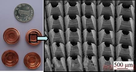
Figure 3 Three-dimensional boiling structures at evaporation end
2.3 Solid-phase sintering of wick
In order to study the performance of the heat sink, red copper powder is applied to sintering due to the high thermal conductivity and good sintering performance. The principle of the solid-phase sintering of the wick is shown in Figure 3. As the phase change heat sink is made up of main-body and end-cover, the sintering principles for these two parts are different. To ensure that the mould can be removed from the sintered wick of main-body and end-cover, 1Cr13 stainless steel material is used for the mould. The principle of the solid-phase sintering of the main-body wick is shown in Figure 4(a). First, a certain thickness of copper powder is evenly put into the bottom of the heat sink main-body. Mould 1 is used to control the thickness of the copper powder in wall 1. Subsequently, copper powder with the same thickness is evenly placed onto the step whose thickness is controlled by mould 2. Before the sintering of main-body, mould 4 is put in to prevent the copper powder into the fitting place between main-body and end-cover unable to assembly. Mould 5 is then placed to prevent copper powder from draining off from the vent. A certain thickness of copper powder is evenly put into the bottom of the heat sink end-cover, and then compressed tightly with mould 3, as shown in Figure 4(b). When the adjustment of copper powder thickness is completed, main-body and end-cover are put together into the sintering furnace under a certain sintering temperature and with a certain sintering time. After sintering, the moulds are taken out, and a layer of wick is formed as the backflow passage of the working medium, and the cavity is formed served as the steam channel. Thus, the working medium moves round and round by the capillary force of the wick to conduct the heat from the hot end to the cold end.

Figure 4 Sintering principle of wick:
2.4 Encapsulation of high power LED phase change heat sink
Working medium is the carrier of phase change heat sink system. There is a great influence of the vacuum of the cavity and the appropriate volume of the liquid working medium onto the heat transfer performance of the heat sink. Accordingly, heat sink main-body and end-cover should first be welded together to form a cavity, and then perfusing and vacuumizing should be performed.
The material of main-body, end-cover and vacuum tube is red copper. Thus the material of tin is chosen for welding. During welding, the alloy layer is formed due to the diffusion of tin solder to the copper plate. The end-cover and vacuum tube are first welded together. The oil stain and oxide layer of the copper pipe are removed and cleaned, and a certain amount of solder is put around the end-cover tube. Subsequently, the copper tube is inserted into the end-cover tube to heat. The two parts are welded together when the solder is melted. After the welding of end-cover with the vacuum tube, the main-body and end-cover are welded together.
The purification treatment to working medium should be conducted before filling to remove the non-condensable gases and impurities etc. Otherwise, the non-condensable gases will be taken to and accumulate in the condensation end, resulting in the reduction of effective condensation areas. Reverse osmosis (RO) is conducted in this study to remove all of the particles, bacteria and organics having a molecular weight greater than 300. The impurity removal rate can reach 99%.
Vacuum-pumping is conducted after the accomplishment of working fluid perfusion, whose principle is shown in Figure 5. First, vacuum valves 1 and 3 are open, and then the vacuum pump is started, and a vacuum gauge is applied to displacing the vacuum degree of the whole system. When the vacuum degree reaches 0.13�C1.3 Pa, the diffusion pump is open, and vacuum valve 3 is closed. Subsequently, vacuum valve 2 is open for high vacuum-pumping.

Figure 5 Principle of vacuum-pumping
After vacuum-pumping, the vacuum degree of heat sink will reach 1.33��10�C3 Pa. The whole process of pumping takes about 5�C6 s. The sealed cavity is formed inside the heat sink after the perfusion and vacuum-pumping. Finally, the hydraulic seal point of the vacuum tube is welded in order to assure the stability of the seal, as shown in Figure 6.

Figure 6 Optical image of phase change heat sink
3 Testing system of high power LED
Heat transfer performance test of the phase change heat sink for high power LED is conducted in this study, and subsequently the heat transfer performance of the phase change heat sink is compared with that of metal solid heat sink. The heat transfer performance test system mainly includes the heating part, the cooling part and temperature acquisition part, as shown in Figure 7. During the experiment, the simulated heat source and the phase change heat sink are wrapped with insulating materials to avoid heat loss, and at the same time, natural convection cooling is adopted in order to improve the reliability of the LED. Finned aluminum pieces are installed on the back of the end-cover of the phase change heat sink for heat dissipation.
During the test, temperature measuring points T1, T2, T3 and T4 are evenly located at the evaporation end along radius direction. Likewise, temperature measuring points T5, T6, T7 and T8 are evenly located at the condensation end along radius direction, as shown in Figure 8. Eight K-type thermocouples are connected to a temperature acquisition module ADAM-4018, and then input to the computer through conversion module ADAM-4520. The signals are acquired through the test program in LabVIEW environment and are displayed in a real-time manner. The sampling frequency is 1 s�C1.
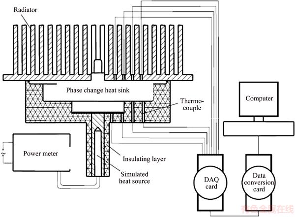
Figure 7 Heat transfer performance testing principle

Figure 8 Locations of thermocouples:
4 Results and discussion
4.1 Effect of heating power on performance of phase change heat sink
The heat transfer performance of the phase change heat sink with different input power is tested. The test results using pure water as the working fluid under heat load of 3, 5 and 10 W are shown in Figure 9, respectively. It is seen that temperature increases with the increase of input power. When input power is 3 W, the rising speed of each point is slow. The time duration to reach system balance takes about 60 min. The highest temperature at the evaporation end is 39.2 ��C, and the lowest temperature at the condensation end is 38.6 ��C. When the input heat power rises to 5 W, the temperature rising speed is increased, and the time to reach the balance is about 48 min. The highest temperature at the evaporation end is 54.7 ��C, and the minimum temperature at the condensation end is 53.8 ��C. When the input heat power rises to 10 W, the temperature of every measuring point rises rapidly, and it takes about 30 min to get to the balance. The highest temperature at the evaporation end is 85.4 ��C, and the minimum temperature at the condensation end is 84 ��C.
4.2 Effect of working fluid on performance of phase change heat sink
The test results using ethanol as working fluid under the thermal load of 3, 5 and 10 W are shown in Figure 10. When the input power is 3 W or 5 W,the highest temperature at the evaporation end using ethanol as working fluid is lower than that using pure water as working substance. However, when the input power increases to 10 W, the highest temperature at the evaporation end using ethanol as working fluid is higher than that using pure water as working substance. This is due to the fact that heat capacity of water is large, while the heat capacity of ethanol is lower. When the input power is relatively low, ethanol can start quickly, while the water requires more heat to boiling. This leads to a higher equilibrium temperature of water. When the input power gets to 10 W, a large amount of heat will lead to faster boiling of water. Therefore, the equilibrium temperature using water as working fluid is lower than that using ethanol. When the input power is 3 W, the maximum temperature at the evaporation end is 38.4 ��C, and the minimum temperature at the condensation end is 37.9 ��C. When the input heat power rises to 5 W, the temperature rising speed increases. The maximum temperature at the evaporation end is 53.8 ��C, and the minimum temperature at the condensation end is 53 ��C. When the input heat power rises to 10 W, the temperature of every measuring point rises rapidly. The maximum temperature at the evaporation end is 86.8 ��C, and the minimum temperature at the condensation end is 85.2 ��C.

Figure 9 Heat transfer performance of phase change heat sink under different thermal load:

Figure 10 Heat transfer performance of phase change heat sink with different working fluid:
Thermal resistance of the phase change heat sink under different heat load with different working fluid is shown in Figure 11. The average thermal resistance, Rave, is calculated as the following equation,
 (1)
(1)
where Tevp-ave is the average temperature of the evaporation end; Tcond-ave is the average temperature of the condensation end; Qin is the input heat power. With the increase of input power, the temperature at the evaporation end rises, but the thermal resistance is on the decline. When the input power is low, thermal resistance using pure water as the working medium is greater than that using ethanol as the working medium. When the input heat power is close to 7.5 W, the thermal resistances of the two are equal. With a further increase of input power, thermal resistance using pure water as the working medium is smaller than that using ethanol as the working medium. Thus, it is found that the phase change heat sink with ethanol as working medium is suitable for working conditions under small input thermal power, while the phase change heat sink with water as working medium is suitable for working conditions under large input thermal power.

Figure 11 Thermal resistance of phase change heat sink with different working fluids
4.3 Phase change heat sink vs metal solid heat sink
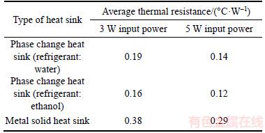
Heat transfer performance of the metal solid heat sink is tested under the input power of 3 W and 5 W respectively. Under the input power of 3 W, the balance temperature of the metal solid heat sink is up to 68.2 ��C, as shown in Figure 12(a). When the input power further increases to 5 W, the maximum temperature has reached 101.7 ��C, as shown in Figure 12(b). Therefore, metal solid heat sink is commonly used under the input power fewer than 3 W for heat dissipation.It is seen from Table 1 that the average thermal resistance of the phase change heat sink is smaller than that of metal solid heat sink. The average thermal resistance of solid metal heat sink is about 2 times the average thermal resistance of the phase change heat sink. Under the input power of 3 W and 5 W, the best heat transfer performance is achieved when ethanol is chosen as the working fluid. Therefore, the proposed phase change heat sink in this study has excellent heat transfer performance is very suitable for LED packaging up to the input power of 10 W.

Figure 12 Heat transfer performance of traditional metal solid heat sink:
Table 1 Average thermal resistance of phase change heat sink and metal solid heat sink
5 Conclusions
This work proposed a new-type of miniaturized phase change heat sink for high power LED packaging.
1) The fabrication process of miniaturized phase change heat sink is investigated, upon which all parts of the heat sink are manufactured including the machining of main-body and end-cover of the heat sink, the formation of three-dimensional boiling structures at the evaporation end, the sintering of the wick, and the encapsulation of high power LED phase change heat sink.
2) With the assistance of the developed testing system, heat transfer performance of the heat sink is tested under the condition of natural convection, upon which the influence of thermal load and working medium on the heat transfer performance is investigated.
3) The heat transfer performance of the developed miniaturized phase change heat sink is compared with that of metal solid heat sink. Results show that the developed miniaturized phase change heat sink presents much better heat transfer performance over traditional metal solid heat sink, and is very suitable for the packaging of high power LED.
References
[1] NARENDRAN N, GU Y, FREYSSINIER J P, YU H, DENG L. Solid-state lighting: Failure analysis of white LEDs [J]. Journal of Crystal Growth, 2004, 268(3, 4): 449�C456.
[2] LUO Xiao-bing, HU Run, LIU Sheng, WANG Kai. Heat and fluid flow in high-power LED packaging and applications [J]. Progress in Energy and Combustion Science, 2016, 56: 1�C32.
[3] ZHAO T, CHEN R. Recent progress in understanding of coupled heat/mass transport and electrochemical reactions in fuel cells [J]. International Journal of Energy Research, 2011, 35(1): 15�C23.
[4] FENG Ming-jie, WANG En-gang, WANG Hai, LI Yan-dong, LIU Bing. Numerical simulation on boiling heat transfer of evaporation cooling in a billet reheating furnace [J]. Journal of Central South University, 2016, 23(6): 1515�C1524.
[5] FSADNI A M, WHITTY J P M. A review on the two-phase heat transfer characteristics in helically coiled tube heat exchangers [J]. International Journal of Heat & Mass Transfer, 2016, 95: 551�C565.
[6] DENG Da-xiang, WAN Wei, SHAO Hao-ran, TANG Yong, FENG Jun-yuan, ZENG Jian. Effects of operation parameters on flow boiling characteristics of heat sink cooling systems with reentrant porous microchannels [J]. Energy Conversion and Management, 2015, 96: 340�C351.
[7] HOSSEIN G, MOSLEM N. Thermo-structural analysis on evaluating effects of friction and transient heat transfer on performance of gears in high-precision assemblies [J]. Journal of Central South University, 2017, 24(1): 71�C80.
[8] KANG Lei, ZHAO Gang, TIAN Ni, ZHANG Hai-tao. Computation of synthetic surface heat transfer coefficient of 7B50 ultra-high-strength aluminum alloy during spray quenching [J]. Transactions of Nonferrous Metals Society of China, 2018, 28(5): 989�C997.
[9] ARSHAD W, ALI H M. Graphene nanoplatelets nanofluids thermal and hydrodynamic performance on integral fin heat sink [J]. International Journal of Heat and Mass Transfer, 2017, 107: 995�C1001.
[10] XIANG Jian-hua, ZHANG Chun-liang, JIANG Fan, LIU Xiao-chu, TANG Yong. Fabrication and testing of phase change heat sink for high power LED [J]. Transactions of Nonferrous Metals Society of China, 2011, 21(9): 2066�C2071.
[11] XIANG Jian-hua, DUAN Ji-an, ZHOU Hai-bo, ZHANG Chun-liang, LIU Gui-yun, ZHOU Chao. Forming mechanism of three-dimensional integral fin based on flat surface [J]. Journal of Central South University, 2015, 22(5): 1660�C1666.
[12] ALI H M, ARSHAD W. Effect of channel angle of pin-fin heat sink on heat transfer performance using water based graphene nanoplatelets nanofluids [J]. International Journal of Heat & Mass Transfer, 2016, 106: 465�C472.
[13] ARSHAD W, ALI H M. Experimental investigation of heat transfer and pressure drop in a straight minichannel heat sink using TiO2 nanofluid [J]. International Journal of Heat & Mass Transfer, 2017, 248: 248�C256.
[14] YANG K S, CHUNG C H, LEE M T, CHIANG S B, WONG C H, WANG C C. An experimental study on the heat dissipation of LED lighting module using metal/carbon foam [J]. International Communications in Heat & Mass Transfer, 2013, 48(11): 73�C79.
[15] HA M, GRAHAM S. Development of a thermal resistance model for chip-on-board packaging of high power LED arrays [J]. Microelectronics Reliability, 2012, 52(5): 836�C844.
[16] XIAO Cheng-di, LIAO Hai-long, WANG Yan, LI Jun-hui, ZHU Wen-hui. A novel automated heat-pipe cooling device for high-power LEDs [J]. Applied Thermal Engineering, 2017, 111: 1320�C1329.
[17] ZHAO Xin-jie, CAI Yi-xi, WANG Jing, LI Xiao-hua, ZHANG Chun. Thermal model design and analysis of the high-power LED automotive headlight cooling device [J]. Applied Thermal Engineering, 2015, 75: 248�C258.
(Edited by YANG Hua)
���ĵ���
����LED��������ȳ��������ܲ���
ժҪ��������й�̬�����ȳ��ڴ���LEDɢ�ȷ���ľ����ԣ���Ʋ�������һ��������ȳ������ȣ��о��˸�������ȳ��ļӹ����գ������ȳ�����Ͷ˸ǵļӹ�������������ά���ڽṹ���Ρ���Һо�ս��Լ�����ȳ��ķ�װ��Ȼ���ڿ����IJ���ϵͳ��������ȳ�����Ȼ���������½��д������ܲ��ԣ��о������غɺ��ʶԴ������ܵ�Ӱ�졣���������ȳ��Ĵ����������̬�����ȳ����бȽϡ��о����������������ȳ����кܺõĴ������ܣ��������ڴ���LED�ķ�װ��
�ؼ��ʣ�С������ȳ�����ά���۽ṹ����Һо�ս�������ܲ���
Foundation item: Projects(51575115, 51775122) supported by the National Natural Science Foundation of China
Received date: 2018-03-20; Accepted date: 2018-06-15
Corresponding author: XIANG Jian-hua, PhD; Tel: +86�C20�C39366923; E-mail: xiangjh@gzhu.edu.cn; ORCID: 0000-0001-9763-1279

