
Fatigue fracture of high-strength Al-Zn-Mg-Cu alloy
JIAN Hai-gen(蹇海根), JIANG Feng(姜 锋), WEN Kang(文 康),
JIANG Long(蒋 龙), HUANG Hong-feng(黄宏锋), WEI Li-li(韦莉莉)
School of Materials Science and Engineering, Central South University, Changsha 410083, China
Received 24 June 2008; accepted 2 March 2009
Abstract: X-ray diffractometry(XRD), optical microscopy(OM), scanning electron microscopy(SEM) were used to study the fatigue fracture of the T7451 Al-Zn-Mg-Cu alloy (470 ℃, 60 min+115 ℃, 8 h+165 ℃, 16 h). The study reveals mainly the microscopic structure of the alloy in the process of crack formation and crack growth. The fatigue fracture is characterized by three zones: fatigue crack source zone, fatigue crack propagation zone and fatigue fracture zone. The fatigue damage preferably incubates at the fractured inclusion particles at or near (about 25 μm) the specimen free surfaces, and these brittle Fe-rich intermetallic inclusion particles are (7-10) μm×(11-14) μm in size. Some features such as “feather-like”, “river and range” and boundary extrusions can be observed in the fatigue propagation zone, and in the fatigue fracture zone the surface is rough and uneven.
Key words: Al-Zn-Mg-Cu alloy; fatigue fracture; fatigue crack propagation
1 Introduction
The Al-Zn-Mg-Cu alloy has properties such as low density, high strength, high hardness and good processing performances. This kind of alloy has been widely used in the aerospace field and civil industry, and is one of the most important structural materials in the aerospace industry[1-3]. Before 1960s, people usually adopted the peak-aging treatment on this kind of alloy in order to get the highest strength value. Under this condition, the strengthening phases inside the grains are G.P. zone and the η′ phases; meanwhile the grain boundary is a continuous precipitate chain which has a high susceptibility to stress corrosion cracking(SCC) and relatively low fracture toughness. To give a consideration to both the strength and stress corrosion cracking resistance of the alloy, some other treatments like T76, T736(T74) and RRA had been developed. Nowadays, these methods have been widely used in the heat treatments of some structural components such as airframe, supporting parts of the landing gears, wing cover, hull and rivet[4-6].
Being the main structural materials in the aircraft industry, these components are usually applied with a cyclic loading, so that it requires a higher fatigue resistance. In the last few decades, large number of research on the fatigue properties of the alloy had been carried out. Through the GOODMAN experiment people set up a fatigue life diagram considering mean stress and provided us some basic data for fatigue design[7]. MANSON and COFFIN proposed the low cycle fatigue fracture laws for material evaluation, i.e. the ?ε―N curve[8]. The fracture mechanics was established in the 1960s, and then it was used to study the fatigue crack propagation characteristic of the material. PARIS and ERDOGAN[9] proposed the general relationship between the crack propagation rate and the stress intensity factor range (?K). In this work, we focused on the microstructure of the fatigue crack propagation zone, because different microstructures relate to different growth threshold and propagation rate of the crack, then these would affect the fatigue properties of the alloy.
2 Experimental
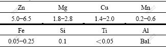
The alloy plates used in this experiment were supplied by the Northeast Light Alloy Corporation, China. After smelting, casting, and homogenization treatment, the plates were hot-rolled into plates with the thickness of 30 mm. The chemical composition of the alloy is shown in Table 1. The alloy first had a solution treatment of 470 ℃, 60 min and a rapid quenching, after that there was a 2% pre-strain on it to release the quenched residual stress. Then, the step of 115 ℃, 8 h+165 ℃, 16 h double aging treatment was followed.
Table 1 Chemical composition of Al-Zn-Mg-Cu alloy (mass fraction, %)
The fatigue specimen was sampled along the longitudinal direction of the plates. Fig.1 shows the dimension and orientation of the sample. In order to get a further understanding on the fatigue property of the 30 mm Al-Zn-Mg-Cu alloy plates from microscopic view, metallographical observation, XRD phase analysis and SEM observation were performed on the alloy plates after heat treatment.
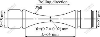
Fig.1 Orientation and dimensions of fatigue sample
The XRD analysis was carried out on the Rigaku D/Max 2500. The fatigue test was taken on the MTS810 hydraulic servo-machine. The load wave was sinusoidal with a frequency of 20 Hz, and the stress ratio R=0.1. KYKY-2800 SEM was used to observe the fatigue fracture, and the accelerating voltage was 20 kV.
3 Experimental results
3.1 XRD phase analysis
The XRD pattern of the Al-Zn-Mg-Cu alloy plates after T7451 treatment is shown in Fig.2. It is shown that in addition to the Al matrix solid solution, there are massive η'(MgZn2) precipitates and particles like Al2CuMg and Mg32(Al, Zn)49.
3.2 Fatigue crack formation
Crossing the crack source zone, we got the cross-section of crack propagation path, and then ground it. The metallographs of cross-section at or near the crack source zone are shown in Figs.3(a) and (b), and the SEM micrographs of the surface of the fatigue sample are shown in Figs.3(c) and (d).
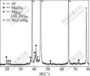
Fig.2 XRD spectrum of Al-Zn-Mg-Cu alloy plate
The cracks near the crack source zone of the fracture are intergranular (Fig.3(a)). Going deep into a certain depth, the cracks transform into transcrystalline (Fig.3(b)). In Fig.3(c), some particles can be identified easily due to their distinct hoar color. The energy spectrum analysis confirmed that they are Fe-rich intermetallic particles. Fig.3(d) reveals that on the surface of the specimen there are some coarse particles, and the fatigue damage is obvious. The specimen surface is crisscrossed by some clearly visible micro-cracks.
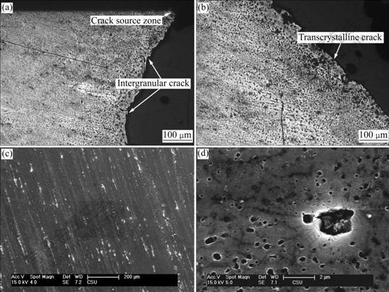
Fig.3 OM microstructures of fatigue fracture (a, b) and SEM micrographs of sample surface (c, d)
3.3 Morphology of fracture
The characteristic of fatigue fracture of the sample with stress amplitude of 330 MPa is shown in Fig.4. The fracture is obviously composed of three zones: crack source zone, crack propagation zone and fatigue fracture zone. The crack source zone is approximately 25 μm from the free surface of the specimen. In the region close to the crack source zone, the cracks show obvious radial morphology. Then with the propagation of fatigue cracks, the opening mouths of the cracks become broader; the cracks distribute sparser; and the growth of the crack is accelerated[10]. When the crack length increases to the critical crack length of the material, the material fractures instantly and meanwhile forms a rough surface. In the area near the free surface we could see the slanted rupture. On the whole fracture surface, the crack source zone is the smallest in size, and the fatigue crack propagation zone takes up half of the surface.
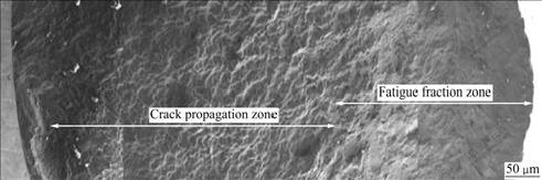
Fig.4 Fractograph of fatigue fracture samples for Al-Zn-Mg-Cu alloy (stress is 330 MPa, R=0.1)
Fig.5 shows SEM images of the initiation sites of the fatigue crack on the Al-Zn-Mg-Cu alloy specimen. From the high magnification fractogragh of the fatigue surface we can see the particles that induced the fatigue crack and the nearby fractured inclusion particles. The voids left by the missing particles indicate that the particles that induced the initial formation of the fatigue damage are (7-10) μm×(11-14) μm in size.
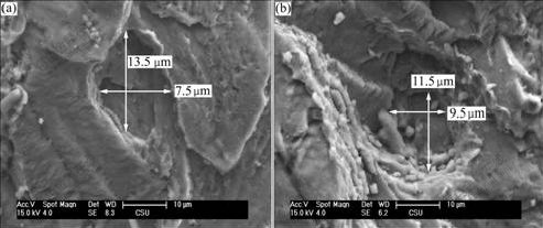
Fig.5 SEM images of fatigue crack initiation sites for samples
3.4 Fatigue crack growth
Following fatigue damage incubation, the fatigue propagates into the matrix and towards the center of the specimens as shown in Fig.6(a). The fracture surface of the specimen is perpendicular to the uniaxial loading direction, which is also the rolling direction of the alloy plates. Initially, in the vicinity of the crack source, the fractographs reveal a nonplanar region. In this region, no striations are observed. As the crack propagates further, the fracture surface displays many micro-cliffs, arranged in an ordered fashion parallel to the crack propagation direction. This feature is commonly called “river and range” in Ref.[11]. Striations are visible on the micro-cliffs. Under high magnification, the micro-cliffs have a step-like pattern formed inside of a grain, which seems to demonstrate lateral slippage at the crack tip during fatigue crack propagation.
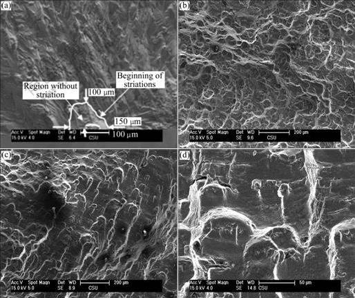
Fig.6 SEM images of crack initiation and propagation sites: (a) Crack source and further crack propagation; (b, c) Feather-like features; (d) Secondary fractures
The phenomenon known in the literature as “feather-like features” is observed, accompanied with grain boundary extrusions as shown in Figs.6(b) and (c). High magnification images of these areas show many dimples with precipitant particles located at the center, signifying pore development under microscopic plasticity. In the meantime, some secondary fractures at the grain boundaries are noticeable as shown in Fig.6(d).
3.5 Fatigue striations
Fig.7(a) shows the overall crack growth region at the facture surface. The striation is first visible at a zone of 100 μm×150 μm (Fig.6(a)) from the crack formation site. Figs.7(b)-(d) show the spacing of the striation at various distances from the crack formation sites. There is a uniform increase in striation distance as the crack length increases. The steady increase of striation distances indicates steady-state crack propagation in the region.
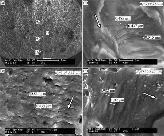
Fig.7 SEM images of fatigue striation (d shows distance of fatigue striation measured in crack initiation site, arrows indicate crack propagation directions): (b) Striation measured at 299.78 μm from formation site; (c) Striation measured at 1 040.83 μm; (d) Striation measured at 2 329.47 μm
4 Discussion
Fatigue cracks are formed and driven by different mechanisms at various stages of their evolution. The incubation of fatigue damage appears at Fe-rich intermetallic particles at or near the free boundary of the specimens. The fracture surfaces of the particles are mostly perpendicular to the uniaxial loading direction, and the cracks propagate from the free boundary to inside, which is corresponding to a maximum principle stress direction. The fracture of the inclusion particles is induced when the accumulation of cyclic loading reaches the ultimate tensile strength[12].
In Figs.3(c) and (d), thousands of inclusion particles are located near or at the free surface. However, only one or a few fractured particles induce predominant fatigue cracks and most of the fractured particles do not induce fatigue cracks in the matrix.
Consider a scenario with three particles located on the free surface of the specimen along the normal, the traverse and the bisection of the two directions (denoted A-C in Fig.8). Let the three points be centers and draw three circles of 40 μm diameter representing imaginary cracks. The circle at point B intersects the greatest number of grain boundaries of the three points, and the circle at point A intersects the fewest grain boundaries. The grain boundaries normally act as a blockage of crack growth and reduce the crack driving forces due to the energy induced by pile-up dislocations. Therefore, the fractured particles on the free surface of the specimens at point A, with the surface normal direction coinciding with the short transverse direction of the rolling plate, are more likely to induce final fatigue failure than the particles at points B and C, given that other microstructural features remain the same.
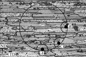
Fig.8 Schematic drawing of cross section of specimen with background of grain morphology according to rolling direction
Following fatigue crack incubation, the deviation of growth direction occurs during the propagating process due to the various resistances acted on the crack tips[13]. Thereafter the fatigue cracks propagate continuously on each plane respectively, and different fracture surfaces intersect and form some steps which constitutes the radial morphology on the fracture surface (Fig.4). And the grain boundary extrusion grows up generally with the increase of the number of cycles. The corresponding squeezing part propagates towards the depth of the slip band and forms a crystallographic incision. Based on the physical model of the fatigue crack growth, the fatigue fashioned subcritical propagation occurs during the process of constant opening and closing of the crack tip [14]. The fatigue cracks enter the stable growth zone when they orient perpendicularly to the loading direction. In this region, besides some fracture features in common with that under static loading, such as intercrystalline and dimples, the striation that is peculiar to the fatigue fracture could also be observed. The arraying directions of the striations at different regions are not identical, but the propagation trend of the micro cracks is basically consistent with the growth direction of the macro cracks. The striations on the fracture surface are basically a group of textures parallel to each other, and their normal direction is consistent with the propagation direction of the cracks[15]. Depending on grain misorientation, grain boundaries and second phase particles, the crack would be transferred onto another flat surface; therefore, striation in different regions sometimes locates at planes of different height. In the regions where striations could be recognized, the striation distances broaden as the crack increases in size.
5 Conclusions
1) Fatigue damage incubates at the fractured Fe-rich inclusion particles at or near the specimen free surfaces. However, only one or a few fractured particles induce predominant fatigue cracks and most of the fractured particles do not induce fatigue cracks in the matrix. The particles that induce the initial formation of the fatigue damage are (7-10) μm×(11-14) μm in size.
2) The fatigue fracture is composed of fatigue crack source zone, fatigue crack propagation zone and fatigue fracture zone. The crack source zone is approximately 25 μm from the free surface of the specimen. In the region near the crack source, the cracks show obvious radial morphology. Then with the propagation of fatigue cracks, the cracks distribute sparser, and the growth of the cracks is accelerated. The fracture morphology of the fracture zone is similar to that of the static loading fracture, and the surface is rough and uneven. On the whole fracture surface, the crack source zone is the smallest in size, and the fatigue crack propagation zone take up half of the surface.
3) At the zone of 100 μm×150 μm from the crack formation site, there is no striation. After further propagation of cracks, some typical fracture morphology such as “river and range”, “feather-like features”, dimples and secondary cracks with the grain boundary extrusions could be observed. In the regions where striations could be recognized, the striation distances broaden as the crack increases in size.
References
[1] JIAN Hai-gen, JIANG Feng, Xu Zhong-yan, GUAN Di-kai. Study progress of high strength and tenacity Al-Zn-Mg-Cu aluminum alloy for aviation [J]. Hot Working Technology, 2006, 6(35): 66-71. (in Chinese)
[2] WEI Qiang, XIONG Bai-qing, ZHANG Yong-an. Production of high strength Al-Zn-Mg-Cu alloys by spray forming process [J]. Trans Nonfrrous Met Soc China, 2001, 11(2): 258-261.
[3] LIU Xiao-tao, CUI Jian-zhong. Progress in research on ultra high strength Al-Zn-Mg-Cu alloy [J]. Materials Review, 2005, 19(3): 47-50. (in Chinese)
[4] JIAN Hai-gen, JIANG Feng, GUAN Di-kai, ZHANG Qian. Effect of solution treatment on microstructure and properties of 7B04 aluminum alloy [J]. Transactions of Material and Heat Treatment, 2007, 28(3): 72-75. (in Chinese)
[5] HOU Xian-zhi, LIU Xian-dong, FENG Zheng-hai. Research about heat treatment and microstructure of 7055 aluminum all0y [J]. Light Alloy Fabrication Technology, 2007, 35(7): 47-49. (in Chinese)
[6] NING Ai-lin, LIU Zhi-yi, FENG Chun. Analysis on the behavior of exceeding peak ageing strength of aluminum alloy at condition of retrogression and reageing [J]. Acta Metallurgica Sinica, 2006, 42(12): 1253-1258. (in Chinese)
[7] DU Feng-shan, YAN Liang, DAI Sheng-long, YANG Shou-jie. Study on fatigue performance of high strength aluminum alloy [J]. Journal of Aeronautical Materials, 2009, 29(1): 96-100. (in Chinese).
[8] MANSON S S. National aavisory committee for aeronautics [M]. Cleveland, NACA TN-2933, 1954.
[9] PARIS P C, ERDOGAN F. A critical analysis of crack propagation law [J]. Transaction ASME, Journal of Basic Engineering, 1963, 85(4): 528.
[10] AL-RUBAIE K S, BARROSO E K L, GODEFROID L B. Fatigue crack growth analysis of pre-strained 7475-T7351 aluminum alloy [J]. International Journal of Fatigue, 2006, 28: 934-942.
[11] FAJDIGA G, SRAML M. Fatigue crack initiation and propagation under cyclic contact loading [J]. Engineering Fracture Mechanics, 2009, 20(2): 14-18. (in Chinese)
[12] ZHONG Qun-peng, ZHAO Zi-hua, ZHANG Zheng. Development of “Fractography” and research of fracture micromechanism [J]. Journal of Mechanical Strength, 2005, 27(3): 358-370. (in Chinese)
[13] DING Chuan-fu, LIU Jian-zhong, WU Xue-ren. An investigation of small-crack and long-crack propagation behavior in titanium alloy TC4 and aluminum alloy 7475-T7351 [J]. Journal of Aeronautical Materials, 2005, 25(6): 11-16. (in Chinese)
[14] FROUSTEY C, LATAILLADE J L. Influence of the microstructure of aluminium alloys on their residual impact properties after a fatigue loading program [J]. Mater Sci Eng A, 2009, 500(1): 155-163.
[15] XU Fei, KANG Ge-wen, REN Wen-wei. Feature extraction of Zr-4 low fatigue fracture images and fracture analysis [J]. Journal of Chinese Electron Microscopy Society, 2006, 25(2): 113-117.
Foundation item: Project(2005DFA50550) supported by the Key International Science and Technology Cooperation Program of China
Corresponding author: JIANG Feng; Tel: +86-13787009528; E-mail: jfeng@mail.csu.edu.cn
DOI: 10.1016/S1003-6326(08)60402-1
(Edited by YUAN Sai-qian)

