Method to analyze wrinkled membranes with zero shear modulus and equivalent stiffness
来源期刊:中南大学学报(英文版)2011年第5期
论文作者:赵冉 魏德敏 孙文波
文章页码:1700 - 1708
Key words:membrane structures; finite element method; wrinkling analysis; shear modulus; zero-setting; equivalent stiffness
Abstract:
To solve the problems of divergence, low accuracy and project application of membrane wrinkling analysis, an analysis method of zero shear modulus and equivalent stiffness was proposed. This method is an improvement to the previous method (Method I) of local coordinate transposition and stiffness equivalence. The new method is derived and the feasibility is theoretically proved. A small-scale membrane structure is analyzed by the two methods, and the results show that the computational efficiency of the new method (Method II) is approximately 23 times that of Method I. When Method II is applied to a large-scale membrane stadium structure, it is found that this new method can quickly make the second principal stress of one way wrinkled elements zero, and make the two principal stresses of two-way wrinkled elements zero as well. It could attain the correct load responses right after the appearance of wrinkled elements, which indicates that Method II can be applied to wrinkling analysis of large-scale membrane structures.
J. Cent. South Univ. Technol. (2011) 18: 1700-1708
DOI: 10.1007/s11771-011-0891-3![]()
ZHAO Ran(赵冉)1, 2, WEI De-min(魏德敏)1, SUN Wen-bo(孙文波)3
1. State Key Laboratory of Subtropical Building Science, South China University of Technology, Guangzhou 510640, China;
2. CCCC Forth Harbor Engineering Institute Co., Ltd, Guangzhou 510230, China;
3. Architectural Design and Research Institute, South China University of Technology,Guangzhou 510640, China
? Central South University Press and Springer-Verlag Berlin Heidelberg 2011
Abstract: To solve the problems of divergence, low accuracy and project application of membrane wrinkling analysis, an analysis method of zero shear modulus and equivalent stiffness was proposed. This method is an improvement to the previous method (Method I) of local coordinate transposition and stiffness equivalence. The new method is derived and the feasibility is theoretically proved. A small-scale membrane structure is analyzed by the two methods, and the results show that the computational efficiency of the new method (Method II) is approximately 23 times that of Method I. When Method II is applied to a large-scale membrane stadium structure, it is found that this new method can quickly make the second principal stress of one way wrinkled elements zero, and make the two principal stresses of two-way wrinkled elements zero as well. It could attain the correct load responses right after the appearance of wrinkled elements, which indicates that Method II can be applied to wrinkling analysis of large-scale membrane structures.
Key words: membrane structures; finite element method; wrinkling analysis; shear modulus; zero-setting; equivalent stiffness
1 Introduction
Wrinkles of membrane structures are referred as a mode of out-of-plane bending displacement. Membrane structures cannot resist compressive stresses due to the extremely low stiffness in compression and bending. Thus, once membrane structures are subjected to compressive stresses, wrinkles occur in the structures. Based on their configurations, wrinkles can be categorized into one-way wrinkles and two-way wrinkles [1]. For the former, the out-of-plane displacement exists only in one direction and the other direction is in tension, while the latter means that out-of-plane displacement exists in both two directions.
Researches on wrinkles of membranes started at 1920s and the wrinkling analysis theories can be classified into two categories: 1) the tension field theory [2-3] and 2) the thin shell buckling theory [4-6]. The tension field theory deems that once compressive stresses occur, wrinkles will emerge in membrane elements. In this condition, materials will be uniaxially tensile, the maximum principle stress will be positive and the minimum principle stress will be zero. As for the thin shell buckling theory, similarities in deformation characteristics between wrinkles and buckling are considered. The membrane wrinkles can be seen as local buckling of thin shell. The thin shell buckling theory is applicable in measuring stresses and displacements of wrinkles. Finite element method has been widely applied in wrinkling analyses [7-8].
Recently, based on the tension field theory, AKITA and NATORI [2] proposed a new method using sensitivity analysis. This method can be applied to reduce the wrinkles in membrane structures design. WANG et al [9] presented a method to accurately predict the wrinkling characteristics in the membrane by eliminating the singularity of the displacement solution. Based on plane stress conditions and 3D nonlinear elasticity formulations, PIMPRIKAR et al [10] proposed a method to analyze the wrinkles in membrane structures by adopting eight-node membrane elements. LI et al [11], by using numerical and experimental analysis methods in membrane wrinkling analysis, found that the results obtained by both of these analysis methods were consistent well, which verified the validity of the numerical analysis method. Based on the thin shell buckling theory, TESSLER et al [4] simulated the formation of wrinkled deformations in thin-film membranes using the finite element program ABAQUS, and good agreement is observed between the numerical simulations and experimental data. WOO and JENKINS [5] presented a global/local analysis strategy for partly wrinkled membranes, and the accuracy and convergence of this method are also studied. ZHANG et al [6] adopted the thin shell elements to simulate the wrinkle problems in tensioned membrane structures under in-plane loading. By this method, the wavelength, amplitude and direction information of wrinkle in membrane could be obtained. However, up to now, there is rarely a method that can present a good solution to the convergence problem of wrinkle calculations and the practical engineering application.
Recently, a method based on the tension field theory to analyze the wrinkles of membranes has been presented [12]. By using local coordinate transpose and equivalent stiffness, wrinkling analysis can be conducted on small scale membranes. However, this transpose induces strong interactions between adjacent wrinkled elements, hence only one wrinkled element can be processed for every iteration, which makes this method have low accuracy and slow convergence, especially inappropriate for large scale engineering problems. In this work, the method above is modified. For convenience, the terms “Method I” and “Method II” are used: Method I is referred to the method using local coordinate transpose and equivalent stiffness. And Method II is referred to the modified method by setting shear modulus to be zero and equivalent stiffness.
2 Necessity of wrinkling analysis and solution
2.1 Necessity of wrinkling analysis
According to the “Chinese Code for Membrane Structures” [13], wrinkles should not be allowed to appear under load combination I (no wind load included), and wrinkles area ratio should be less than 10% under load combination II (wind load included). Due to the fact that membranes cannot withstand the compression, load responses of membranes will be inaccurate in this circumstance (the second principle stress is negative). Furthermore, with increasing the numbers of wrinkled elements, the calculation will fail to converge and the correct load responses cannot be obtained. Mechanically, wrinkles will change the membrane stiffness and load paths of structures, leading to an adverse effect on shapes and mechanical characteristics of structures. To attain the accurate stress distributions and displacements of membranes, an effective method of wrinkling analysis is highly necessary and it is also the prerequisite of analysis and design of membrane structures.
The most effective technique of wrinkling analysis is to adjust the elasticity matrix in principal stress directions. The process of this technique is as follows. As for one-way wrinkles, the calculated second principal stress σ2 is negative. Actually, its true value should be zero. Therefore, expressions of elasticity matrix can be reversely obtained by setting σ2 to be zero. As for two-way wrinkles, the method is almost the same except setting both σ1 and σ2 to be zero. Then, reliable load responses can be obtained by iterative process. It is noticeable that the elasticity matrix in the principal directions is a full rank matrix with complicated expressions for each matrix element, so it is difficult to obtain reliable stress solution by adjusting elasticity matrix after the occurrence of wrinkles. However, this complex problem can be effectively solved once the directions of principal stresses of wrinkled elements are consistent with their directions of principal axes (directions of local coordinates) and full rank elasticity matrix in principal directions is simplified to elasticity matrix in orthotropic form [12].
2.2 Method I and its shortcomings
The analytical procedure of Method I is as follows. Firstly, transpose the local coordinates of wrinkled elements to the directions of their principal stresses. Secondly, simplify the elasticity matrix in principal stress directions to elasticity matrix in orthotropic form according to the principle of principal stress equivalence. Thirdly, adjust the elasticity matrix in principal directions based on the coincidence of directions between principal stress and local coordinates. The value of zero is set to the minimal principal stress in one-way wrinkled elements, and so do both of the maximal and minimal principal stresses in two-way wrinkled elements. Finally, the elasticity matrix of wrinkled elements is integrated to global stiffness matrix and the true load response of wrinkled elements can be obtained via iteration calculation. Flowchart of analysis of a wrinkled element in a load step is presented in Ref.[12].
Method I performs orthogonal simplification on the elasticity matrix in principal directions and avoids the difficulty of adjusting this full rank matrix. However, when Method I is used in calculation, if too much adjustments of local coordinates are applied to the wrinkled elements at one time, especially for adjacent wrinkled elements, a certain angle will appear between local coordinates and principal stress directions, which is caused by interactions among adjacent wrinkled elements. For the above reasons, only one wrinkled element can be processed at one time, which leads to the slow convergence. Moreover, due to the interactions among wrinkled elements in the iteration process, incorrect identification will occur when there are too many wrinkled elements in local area.
2.3 Method II and its advantages
If the principal stress directions are in coincidence with the local coordinates without transposing local coordinates, all wrinkled elements in one load step can be analyzed at one time. After the appearance of wrinkles, the angle θ between local coordinates and principal stress directions can be determined by the stresses of wrinkled elements [14]:
![]() (1)
(1)
The modified method (Method II) works as follows. If wrinkled elements occur in a certain load step, and shear moduli G12 of all wrinkled elements are basically set to be zero (in finite element analysis, a very small value 10-12 is set), the shear stresses τxy of these elements are about zero for τxy=G12γxy, and the values of their angles θ are also about zero according to Eq.(1). When the direction coincidence happens between the principal stress and local coordinates, with the adjustment of elasticity matrix in principal directions, the values of the minimal principal stress in one-way wrinkled elements and both the maximal and minimal principal stress in two-way wrinkled elements are all changed to zero. Finally, the elasticity matrixes of wrinkled elements are integrated to global stiffness matrix and the true load response of wrinkled elements can be obtained through iteration calculations.
Steps of all wrinkled elements analysis in a load step are as follows.
Step 1: Set shear moduli G12 of all wrinkled elements in a load step to be 10-12.
Step 2: Adjust the elasticity matrix in which G12 is set to be 10-12 according to the principle of principal stress equivalence.
Step 3: Evaluate the corresponding wrinkle types of all wrinkled elements.
Step 4: As for one-way wrinkled element, set σ2 to be zero and adjust the elasticity matrix of corresponding elements. As for two-way wrinkled element, set both σ1 and σ2 to be zero and adjust the elasticity matrix of corresponding elements.
Step 5: Integrate the elasticity matrix of wrinkled elements to global stiffness, then perform the calculation and examine the result.
Step 6: Evaluate whether all wrinkled elements are properly analyzed: as for one-way wrinkled elements, if |σ2|<δ (δ is set to be 0.02 as above) is satisfied, the wrinkled elements are considered to be properly analyzed; if not, return to Step 5 until the stresses of all wrinkled elements can satisfy the default condition; as for two-way wrinkled elements, if both |σ1|<δ and |σ2|<δ (δ takes 0.02) are satisfied, the wrinkled elements are considered to be properly analyzed; if not, return to Step 5 until the stresses of all wrinkled elements can satisfy the default condition.
By comparing the above two methods, it is quite easy to find that Method I attains the direction coincidence between the local coordinates and principal stresses through transposing local coordinates, while Method II through setting shear modulus G12 of all wrinkled elements to be zero. As for Method I, the angle θ between the principal stresses and local coordinates is always changed for one iteration, especially under the condition of larger load steps or adjacent wrinkled elements. Therefore, the change of local coordinates may not keep up pace with that of principal stresses, which leads to the requirement of a large number of iterations. However, Method II is able to adjust the directions of both at one time and avoid the adverse interaction between wrinkled elements.
3 Theoretical analysis of Method II
3.1 Wrinkles criteria
There are three criteria to evaluate wrinkles: the principal stress criterion, the principal strain criterion and the mixed criterion [14-15]. The principal stress criterion may cause a wrong evaluation, and the principal strain criterion can only be applied to isotropic membranes. For the above reasons, the mixed criterion is used in this work. According to the mixed criterion, if the second principal stress σ2 is positive, wrinkles will not occur; if the second principal stress σ2 is not positive, at the same time, the maximal principal strain ε1 is positive, then one-way wrinkles will occur; if the maximal principal strain ε1 is not positive, two-way wrinkles will occur.
3.2 Derivation of equivalent elasticity matrix after adjusting shear modulus G12 to be zero
Under the local coordinates, there is
![]()
where
![]()
![]()
![]()

In directions of principal stresses, there is
![]()
where
![]()
![]()
![]()

Setting G12 to be zero can attain τxy=0 and θ=0. However, incorrect stresses of wrinkled elements may be induced by doing so. Therefore, based on the principle of principal stress equivalence, principal stresses can be kept unchanged, before and after G12 is set to be zero. That is

where ![]() is the principal stress matrix before G12 is set to be zero,
is the principal stress matrix before G12 is set to be zero, ![]() is the principal strain matrix by iterative calculations after G12 is set to be zero. Assume that Poisson ratio ν1 keeps constant and the unknown variables are
is the principal strain matrix by iterative calculations after G12 is set to be zero. Assume that Poisson ratio ν1 keeps constant and the unknown variables are ![]()
![]() and
and ![]() then the solutions are
then the solutions are
![]()
![]()
![]()
Next, the elasticity matrix of wrinkled elements is integrated to global stiffness matrix, and then correct load response of wrinkled elements can be obtained through iteration calculations.
3.3 Theoretical derivation for wrinkling analysis
3.3.1 One-way wrinkled elements
As to the stress for one-way wrinkled elements, the maximal principal stress σ1 should be positive and the second principal stress σ2 should be zero. However, the calculation results show that σ2 is negative. For this reason, the main task of analyzing one-way wrinkled elements is to adjust the elasticity matrix in principal stress directions and guarantee that σ2 is zero. Therefore, by setting σ2 to be zero and assuming that Poisson ratio ν1 is constant, the equations can be obtained as follows:

Then, its solutions can be got as
![]()
![]()
![]()
3.3.2 Two-way wrinkled elements
As to the stress for two-way wrinkled elements, both the maximal principal stress σ1 and the second principal stress σ2 should be zero. By setting σ1 and σ2 to be zero and adjusting elasticity matrix of principal stress directions, the following equation can be obtained:

And its solutions are
![]()

![]()
4 Calculation and discussion
4.1 Comparison of two methods when being applied to small scale membrane
In this work, through the program interface of finite element method (FEM) software Strand7, Visual Fortran programs are created to calculate the equivalence elasticity matrix and perform the wrinkling analysis.
After form-finding analysis, the geometric parameters of saddle-shaped cable-membrane structure can be obtained, as shown in Fig.1. For this small membrane structure, the initial bilateral prestress σ0 is considered to be 2 MPa. The various material parameters of membranes are E1=255 MPa, E1=200 MPa, ν1=0.3, ν2=0.235, and G12=80 MPa. The thickness of membranes is t=1 mm. Other relevant parameters for the cables are as follows: prestress σcable=30 kN, elastic modulus Ecable= 1.5×10⁵ MPa, cross sectional area A=200 mm2. Three- node triangle element is used for membrane elements and the membrane structure is subjected to a uniform vertical load q ranging from 0.00 kN/m2 to 1.00 kN/m2.
It is noticed that wrinkles occur when the uniform vertical load rises to 0.62 kN/m2 for both methods because the same wrinkle criterion is used. Distributions of wrinkled elements by Method I and Method II are described in Fig.2 and Fig.3, respectively. In these two figures, elements in black are bilateral tensile, while elements in white are one-way wrinkles. No two-way wrinkles are found in this example.

Fig.1 Plane (a) and elevation (b) of shaped membrane structure (Unit: mm)
From distributions of wrinkled elements (Figs.2-4), it can be noticed that wrinkled elements for the two methods both arrange along the diagonal of two lower points. They firstly appear at the vicinity of the diagonal ends of two lower points and then gradually expand to the centre of the diagonal and the two lower supporters. Next, they develop along the four cables and the wrinkling areas increase accordingly. At the beginning, distributions of wrinkled elements are biaxial symmetric, and the two methods have almost the same results before the uniform vertical load q reaches 0.74 kN/m2. However, the symmetry for Method I is weakened because of the increase of loads, which is caused by wrong evaluations of wrinkled elements. As for Method II, the distributions of wrinkled elements in all load steps are strictly symmetric. As for distributions of the maximal and the second principal stresses (Figs.5-7), both Method I and Method II make the minimum of second principal stresses basically zero, which indicates that the two methods are all effective in wrinkling analysis. The first principal stresses almost stay the same, which is in accordance with the principle of principal stress equivalence.

Fig.2 Distributions of wrinkled elements with increasing vertical load by Method I (Iteration process time: 33 441 s)
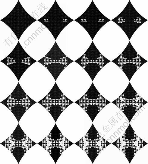
Fig.3 Distributions of wrinkled elements with increasing vertical load by Method II (Iteration process time: 1 451 s)
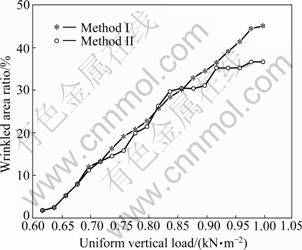
Fig.4 Curves of uniform vertical load vs wrinkled area ratio of two methods
From the iteration process time above (Fig.3 and Fig.4), it can be easily found that Method II is more effective than Method I in computing speed (time ratio is 1/23). Therefore, Method II is more computationally effective for wrinkling analysis and can produce more accurate and reliable results.
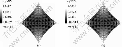
Fig.5 Stress distributions without wrinkling analysis: (a) q=0.62 kN/m2; (b) q=0.89 kN/m2 (divergence)

Fig.6 Stress distributions after wrinkling analysis (q=1.00 kN/m2): (a) σ1 (Method I); (b) σ2 (Method I); (c) σ1 (Method II); (d) σ2 (Method II)

Fig.7 Curves of q vs σ2,min of two methods
4.2 Application of Method II in large scale cable- membrane structure
With a building area of 10 049 m2 and the capability to accommodate 35 000 audiences, Shenzhen Baoan stadium (Fig.8(a)) is an advanced large comprehensive Stadium and will host soccer competitions of the Universiade 2011. The roof of this stadium is a wheel spoke circle cable-membranes structure with 245 m in diameter. The projection of the main structure on the plane is slightly oval-shaped, with 237 m in the long axis, 230 m in the short axis and 54 m in the depth. Finite element method is widely used in these long-span spatial structures at present [16], and its FEM modeling is shown in Fig.8(b).

Fig.8 Effect picture (a) and FEM modeling (b) of Shenzhen Bacan Stadium
In calculating the above model, it is found that the results do not comply with reality under the second class load combination (wind load included). To analyze this structure by using Method I, the calculation speed is very slow, there are many wrong evaluations and some membranes are wrinkled repeatedly. The process is terminated automatically when the iteration time is more than 72 h. Therefore, it can be seen that Method I fails to evaluate the load responses of this structure and cannot successively conduct the wrinkling analysis. When Method II is applied, there are many wrinkled elements at the vicinity of external pressure rings. This is because these rings fail to produce effective tension to membranes under the wind load. Figure 9 shows the load response of this large scale structure under the load combination of dead load, prestress and the maximum unbalanced wind load in zero angle. Elements in white are bilateral tensile; elements in black are two-way wrinkles and elements in grey are one-way wrinkles.
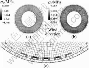
Fig.9 Distributions of σ2 before (a) and after (b) wrinkling analysis (Method II) and distribution of wrinkled elements (c) (Iteration time: 4 062 s)
It can be seen from Fig.9 that, before wrinkling analysis is applied, the minimal value of the second principal stress in membranes reaches -8.404 MPa, which indicates that it is in compression. This result is incorrect because the membranes cannot withstand compressive stress. However, after the wrinkling analysis by Method II, the minimal value of the second principal stress in membranes becomes 0.08 MPa, which indicates that wrinkled elements have been well treated and the calculation accuracy is good enough to satisfy the engineering application requirements. It can also be found that wrinkled elements, both one-way wrinkles and two-way wrinkles, mainly distribute at the windward vicinity of external pressure ring. The symmetric distribution of wrinkled elements and the corresponding loads indicate that the analysis results are quite accurate. Thus, Method II is proved to attain reliable load response after the appearance of compression in membranes. This also indicates that this modified method can conduct wrinkling analysis for large scale cable-membrane structures quickly and effectively.
5 Conclusions
1) The new method adopts zero shear modulus to make the principal stress directions of all wrinkled elements in one load step coincide with their local coordinates at one time. Therefore, the new method can avoid difficulties caused by local coordinates transposition in Method I, and the computation efficiency is improved by 22 times.
2) The new method guarantees that the principal stress directions always coincide with their local coordinates, and avoids the adverse effects of adjacent wrinkled elements. As a result, more accurate load responses of membrane structure after the wrinkled membranes are obtained.
3) The wrinkled elements can be well processed by the new method when they appear. The example shows that the new method can be applied in large-scale membrane structure, and it solves the difficulties in practical projects of wrinkling analysis.
References
[6] ZHANG Jian, YANG Qing-shan, TAN Feng. Analysis of wrinkled membrane structures by thin-shell elements [J]. Engineering Mechanics, 2010, 27(8): 28-34, 39. (in Chinese)
[12] ZHAO Ran, WEI De-min, SUN Wen-bo. Method to analyze wrinkled membranes by using local coordinate transpose and equivalent stiffness [J]. Journal of South China University of Technology: Natural Science Edition, 2009, 37(9): 18-23. (in Chinese)
[13] CECS158. Technical specification for membrane structures [S]. 2004. (in Chinese)
[14] TAN Feng, YANG Qing-shan, LI Zuo-wei. Wrinkling criteria and analysis method for membrane structures [J]. Journal of Beijing Jiaotong University, 2006, 30(1): 35-39. (in Chinese)
[16] TENG Jun, ZHU Yan-huang, ZHOU Feng, LI Hui, OU Jin-ping. Finite element model updating for large span spatial steel structure considering uncertainties [J]. Journal of Central South University of Technology, 2010, 17(4): 857-862.
(Edited by YANG Bing)
Foundation item: Project(020940) supported by the Natural Science Foundation of Guangdong Province, China
Received date: 2010-08-23; Accepted date: 2011-03-11
Corresponding author: ZHAO Ran, PhD Candidate; Tel: +86-13512720627; E-mail: ran.zhao@mail.scut.edu.cn

